US8528480B2 - Warhead - Google Patents
Warhead Download PDFInfo
- Publication number
- US8528480B2 US8528480B2 US12/602,460 US60246008A US8528480B2 US 8528480 B2 US8528480 B2 US 8528480B2 US 60246008 A US60246008 A US 60246008A US 8528480 B2 US8528480 B2 US 8528480B2
- Authority
- US
- United States
- Prior art keywords
- warhead
- casing
- fragments
- front plate
- height
- Prior art date
- Legal status (The legal status is an assumption and is not a legal conclusion. Google has not performed a legal analysis and makes no representation as to the accuracy of the status listed.)
- Expired - Fee Related, expires
Links
Images


Classifications
-
- F—MECHANICAL ENGINEERING; LIGHTING; HEATING; WEAPONS; BLASTING
- F42—AMMUNITION; BLASTING
- F42B—EXPLOSIVE CHARGES, e.g. FOR BLASTING, FIREWORKS, AMMUNITION
- F42B12/00—Projectiles, missiles or mines characterised by the warhead, the intended effect, or the material
- F42B12/02—Projectiles, missiles or mines characterised by the warhead, the intended effect, or the material characterised by the warhead or the intended effect
- F42B12/20—Projectiles, missiles or mines characterised by the warhead, the intended effect, or the material characterised by the warhead or the intended effect of high-explosive type
- F42B12/22—Projectiles, missiles or mines characterised by the warhead, the intended effect, or the material characterised by the warhead or the intended effect of high-explosive type with fragmentation-hull construction
- F42B12/24—Projectiles, missiles or mines characterised by the warhead, the intended effect, or the material characterised by the warhead or the intended effect of high-explosive type with fragmentation-hull construction with grooves, recesses or other wall weakenings
-
- F—MECHANICAL ENGINEERING; LIGHTING; HEATING; WEAPONS; BLASTING
- F42—AMMUNITION; BLASTING
- F42B—EXPLOSIVE CHARGES, e.g. FOR BLASTING, FIREWORKS, AMMUNITION
- F42B10/00—Means for influencing, e.g. improving, the aerodynamic properties of projectiles or missiles; Arrangements on projectiles or missiles for stabilising, steering, range-reducing, range-increasing or fall-retarding
- F42B10/02—Stabilising arrangements
-
- F—MECHANICAL ENGINEERING; LIGHTING; HEATING; WEAPONS; BLASTING
- F42—AMMUNITION; BLASTING
- F42C—AMMUNITION FUZES; ARMING OR SAFETY MEANS THEREFOR
- F42C13/00—Proximity fuzes; Fuzes for remote detonation
- F42C13/006—Proximity fuzes; Fuzes for remote detonation for non-guided, spinning, braked or gravity-driven weapons, e.g. parachute-braked sub-munitions
Definitions
- An explosive munition is used to attack widely different types of targets.
- targets In addition to the bombardment of buildings (infrastructure), in the case of artillery and mortar ammunition, these are so-called semi-hard targets (armored guns, etc.) as well as soft targets (lightly armored or unarmored vehicles, etc.).
- semi-hard targets armored guns, etc.
- soft targets lightly armored or unarmored vehicles, etc.
- EP 1 452 825 A 1 discloses a method for programming the breakup of projectiles. The detonation takes place while maintaining the optimum height with respect to the target, and at the breakup location.
- Known explosive projectiles normally have forged projectile casings which break up into a large number of small and less large fragments on detonation.
- the fragment distribution can be influenced by the treatment of the steel and by so-called break points, within certain limits.
- targets of different strength are penetrated.
- Increasing the proportion of large fragments leads to a reduction in the number of fragments, and this in turn leads to a low fragment density.
- the fragment energy and fragment density must therefore be matched to the attack.
- the fragments When one whishes to attack semi-hard targets, the fragments must be of a certain size and must have a certain energy. If the fragment density is not sufficient, more ammunition is required to carry out the mission.
- only a certain proportion of the fragments are effective, because of the ballistic flight path of the projectiles, with inclined approach angle to the surface of the Earth. The effect against different targets necessitates different projectile descent angles.
- Explosive projectiles are known, inter alia, from DE 602 02 419 T2, DE 601 08 817 T2, DE 20 2004 019 504 U1, DE 295 19 568 U1, DE 39 13 543 C1 and DE 196 26 660 C2.
- the explosive projectile from DE 602 02 419 T2 has an explosive charge which is arranged in a casing.
- the casing has at least two sectors, with the first sector having means which ensure fragment formation. However, the second sector has no such means.
- the explosive projectile according to DE 20 2004 019 504 U1 has an insensitive explosive charge within a projectile casing, and a concrete-breaking penetration head with an insensitive fuze.
- U.S. Pat. No. 5,549,047 A discloses a fuze of complex design which is armed by the unfolded stabilization bands rotating a piercing unit from a safe position, thus releasing a firing capsule. During the process, a further safety pin is released, as a result of which the piercing unit is now pressed by a spring unit against the firing capsule, which has been moved under the piercing unit. This is assisted by balls which engage under a projection in the fuze housing. In the event of soft ground preventing the firing capsule from initiating, provision is made for a self-destruction mechanism to come into play, independently of the fall time and without delay after a defect of the primary initiation system.
- DE 100 40 800 A1 also deals with a bomblet fuze which has a safe setting, as a result of which no dangerous unexploded munitions occur.
- a spin motor On reaching a preselected height above the surface of the Earth a spin motor is initiated which accelerates the payload assembly to a specific rotation speed about the vertical longitudinal axis of the payload.
- the preselected height can be fixed in the design or can be selected as a function of the respective terrain.
- a blocking mechanism On reaching a second preselected height, a blocking mechanism is unlocked, as a result of which the submunitions leave the payload carrier at their respectively instantaneous tangential velocity.
- the invention is based on the object of providing a warhead, the number and effectiveness of which can be optimized for attacking different target types.
- a warhead ( 10 ) for attacking, in particular, semi-hard and/or soft targets wherein the warhead has a casing ( 1 ) which forms fragments, as well as explosive material which is located in the casing ( 1 ), having a front plate ( 2 ) with fragment formation, a proximity sensor ( 3 ), a fuze ( 5 ) for the explosive material and a stabilization band for setting a vertical flight path to the target, wherein initiation of the fuze ( 5 ) by the characteristic of the target to be attacked is governed by presetting a defined height with respect to the target.
- Advantageous refinements of the invention are specified as follows.
- the first embodiment of the invention is modified so that the casing ( 1 ), which forms fragments, is a fragmentation jacket.
- the first embodiment is modified so that the casing ( 1 ), which forms fragments, is a casing with preformed fragments.
- the first embodiment, the second embodiment and the third embodiment are further modified so that preformed fragments are incorporated in the front plate ( 2 ).
- the first embodiment, the second embodiment, the third embodiment and the fourth embodiment are further modified so that the casing ( 1 ) has break points.
- an artillery warhead ( 11 ) is provided that has a projectile casing ( 12 ), an ejection charger ( 13 ) and warheads ( 10 ), which are surrounded by the projectile casing ( 12 ), wherein the warheads ( 10 ) are warheads in accordance with the first embodiment, the second embodiment, the third embodiment, the fourth embodiment or the fifth embodiment of the invention.
- a mortar projectile is provided that has warheads ( 10 ) in accordance with the first embodiment, the second embodiment, the third embodiment, the fourth embodiment or the fifth embodiment of the invention.
- a rocket warhead has a projectile casing ( 12 ), an ejection charge ( 13 ) and warheads ( 10 ), which are surrounded by the projectile casing ( 12 ), wherein the warheads ( 10 ) are warheads in accordance with the first embodiment, the second embodiment, the third embodiment, the fourth embodiment or the fifth embodiment of the invention.
- a dispenser having warheads ( 10 ) is provided, wherein the warheads ( 10 ) are warheads in accordance with the first embodiment, the second embodiment, the third embodiment, the fourth embodiment or the fifth embodiment of the invention.
- the invention is based on the idea of exactly matching the warhead to the attack shortly before the mission, for example, by programming. This is achieved in that the warhead is effective against semi-hard or soft targets by specific deployment of side and front fragments, depending on the detonation height.
- the detonation height or initiation height is signaled to the projectile, depending on the mission, for example by means of programming, and a proximity sensor in the projectile can also initiate detonation.
- One warhead can therefore be used for semi-hard and soft targets, and the effectiveness at the target is governed solely by the detonation height, that is to say the detonation height for the warhead is preset on the basis of the target to be attacked.
- the warhead preferably comprises a metallic casing which surrounds an explosive charge.
- the geometry may have different cross sections and lengths and is designed in an appropriate line for attacking the defined targets.
- the casing preferably comprises a cylindrical steel tube which breaks up into fragments in a known manner when the explosive charge is detonated.
- the casing is, for example, composed of individual rings, each of which is prefragmented on the inside by a large number of grooves.
- the casing On the side facing the target, the casing has a prefragmented steel plate, or the like.
- the steel plate and the side casing may be fragmented differently, in such a way that, for example, the front fragments can be used to attack semi-hard targets, and the side fragments to attack soft targets.
- the invention provides for the warhead to be equipped on the rear face with a stabilization system, for example, an unfolding mechanism, bands and/or a parachute etc., thus resulting in a defined descent angle to the Earth.
- a stabilization system for example, an unfolding mechanism, bands and/or a parachute etc.
- the warhead can be fired into the target area in many different ways. Depending on the way in which it is fired, a plurality of warheads can be stacked in one munition, such as artillery projectiles, mortar projectiles, rockets, dispensers etc.
- the novel warhead can be integrated in the conventionally known manner in a rocket warhead with the same dimensions and ballistic characteristics.
- the warhead then contains a plurality of warhead units in its payload area, the number, size and effect of which are designed for the attack scenarios. They are ejected from the warhead casing at a predetermined height above the target area and then fall with a specific spatial distribution into a defined area which is predetermined by the ejection charge and the ejection height. This area is preselected on the basis of the target type in such a way that the effectiveness radii of the individual submuntions attach, and possibly also overlap.
- each warhead and each warhead unit is equipped with an electronic fuze, which is in turn initiated by a proximity sensor at a height above the target, which can be programmed before firing or, in an alternative mode, has a fixed setting.
- the advantage is that the mission can be carried out with a small number of warheads matched to their effectiveness for the attack. Reducing the number of warheads to carry out a mission now makes it possible to also use reliable fuzes, thus avoiding unexploded munitions.
- a warhead is therefore proposed for attacking, in particular, semi-hard and/or soft targets, having a casing which forms fragments as well as an explosive material which is located in the casing. Furthermore, the warhead has a front plate which forms fragments, in which a proximity sensor is integrated.
- the rear part of the warhead contains a fuze for the firing material or explosive material, as well as a stabilization band for selecting a vertical flight path to the target, wherein the initiation of the fuze by the characteristic of the target to be attacked is governed by presetting a defined height with respect to the target.
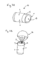
- FIG. 1 shows a warhead
- FIG. 2 shows a cross section through a rocket artillery warhead, with warheads as shown in FIG. 1 .
- FIG. 3 illustrates the stowage space for a stabilization system and one possible embodiment of the stabilization system.
- FIG. 4 illustrates the break points in the fragment jacket and front plate.
- FIG. 5 illustrates the spatial distribution of the impact radii of the submunitions of the warhead.
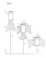
- FIG. 6 illustrates the specific deployment of the fragments in a lateral direction of the warhead, or the front direction of the warhead, or the lateral and the front direction of the warhead depending on the preset detonation height.
- FIG. 1 shows a warhead 10 with a fragment jacket 1 (casing which forms fragments), as well as a front plate 2 with preformed fragments.
- a proximity sensor is annoted as 3 .
- Character reference 4 denotes a physical space for a fuze 5 , which is not illustrated in any more detail, as well as a stowage space for a known stabilization system 15 .
- the warhead 10 also has an explosive material 6 , which is located under the fragment jacket 1 and is functionally and operatively connected in the conventional manner to the fuze 5 .
- the ballistically fired warhead 10 Once the ballistically fired warhead 10 has established a predetermined flight path to the target area, it is separated from the ballistic missile, which is not illustrated in any more detail, in such a way that its stabilization system 16 can unfold.
- the warhead 10 can now descend into the target area, virtually vertically with respect to the target area.
- the fuze 5 On reaching a predetermined height above the target area as confirmed by the proximity sensor 3 , the fuze 5 is fired, and the fragment jacket 1 therefore breaks up.
- the fragment formation can be defined corresponding to the predetermined break points 17 in the fragment jacket 1 .
- the front plate 3 is also likewise destroyed, and its fragment formation is enhanced by the preformed fragments that are incorporated. Side fragments and front fragments therefore act in the target area.
- FIG. 2 shows an artillery warhead 11 with a warhead casing 12 and the warheads 10 , an ejection charge 13 as well as moldings 14 for support.
- the warhead casing 12 is destroyed by the warhead units 10 , which are themselves forced through the casing 12 by the ejection charge 13 .
- the warhead units 10 are ejected to the rear. The operation of the individual units 10 is then the same as that described in FIG. 1 .
- FIGS. 3 A and B show the stowage space for the stabilization system 15 , and one embodiment of the stabilization system 16 .
- FIG. 4 shows the predetermined break points 17 in the fragment jacket 1 and the front plate 3 .
- FIG. 5 shows the spatial distribution 18 of the impact radii 19 of the submunitions of the warhead.
- the outer circumference 20 of the impact radii 19 touch.
- FIG. 6 shows the specific deployment of the fragments in the front direction 22 of the warhead 10 at a preset detonation height H 1 above the ground 21 , the specific deployment of the fragments in the front direction 22 and the lateral direction 23 of the warhead 10 at a preset detonation height H 2 above the ground 21 , and the specific deployment of the fragments in the lateral direction 23 of the warhead 10 at a preset detonation height H 3 above the ground 21 .
- H 1 , H 2 and H 3 are not drawn to scale.
Landscapes
- Engineering & Computer Science (AREA)
- General Engineering & Computer Science (AREA)
- Physics & Mathematics (AREA)
- Fluid Mechanics (AREA)
- Chemical & Material Sciences (AREA)
- Combustion & Propulsion (AREA)
- Radar Systems Or Details Thereof (AREA)
Abstract
Description
Claims (23)
Applications Claiming Priority (4)
| Application Number | Priority Date | Filing Date | Title |
|---|---|---|---|
| DE102007025258 | 2007-05-30 | ||
| DE102007025258.9 | 2007-05-30 | ||
| DE102007025258A DE102007025258A1 (en) | 2007-05-30 | 2007-05-30 | warhead |
| PCT/EP2008/003881 WO2008145259A1 (en) | 2007-05-30 | 2008-05-15 | Warhead |
Publications (2)
| Publication Number | Publication Date |
|---|---|
| US20100192797A1 US20100192797A1 (en) | 2010-08-05 |
| US8528480B2 true US8528480B2 (en) | 2013-09-10 |
Family
ID=39744877
Family Applications (1)
| Application Number | Title | Priority Date | Filing Date |
|---|---|---|---|
| US12/602,460 Expired - Fee Related US8528480B2 (en) | 2007-05-30 | 2008-05-15 | Warhead |
Country Status (9)
| Country | Link |
|---|---|
| US (1) | US8528480B2 (en) |
| EP (1) | EP2150769A1 (en) |
| JP (2) | JP5744514B2 (en) |
| AU (1) | AU2008255286B2 (en) |
| CA (1) | CA2687592C (en) |
| DE (1) | DE102007025258A1 (en) |
| MY (1) | MY152642A (en) |
| WO (1) | WO2008145259A1 (en) |
| ZA (1) | ZA200907758B (en) |
Cited By (4)
| Publication number | Priority date | Publication date | Assignee | Title |
|---|---|---|---|---|
| US20140144311A1 (en) * | 2011-07-14 | 2014-05-29 | Nahum Orlev | Wide area neutralizer |
| US20140299012A1 (en) * | 2011-11-28 | 2014-10-09 | Federal State Budgetary Educational Institution of Higher Professional Education Bauman Moscow State | Fragmentation-beam tank projectile |
| US9243876B1 (en) * | 2014-07-22 | 2016-01-26 | Raytheon Company | Low-collateral damage directed fragmentation munition |
| US10508892B1 (en) * | 2016-08-15 | 2019-12-17 | The United States Of America As Represented By The Secretary Of The Navy | Distributed fuze architecture for highly reliable submunitions |
Families Citing this family (3)
| Publication number | Priority date | Publication date | Assignee | Title |
|---|---|---|---|---|
| DE102009016147A1 (en) | 2009-04-03 | 2010-10-07 | Rheinmetall Soldier Electronics Gmbh | Demountable projectile for use in weapon barrel of weapon system, is demounted into two projectile parts after firing target location, where projectile parts are connected with each other by multiple connecting elements |
| RU2522178C1 (en) * | 2013-03-13 | 2014-07-10 | Открытое акционерное общество "Научно-производственное объединение "СПЛАВ" | Jet projectile warhead |
| US9360284B1 (en) | 2013-03-15 | 2016-06-07 | Vista Outdoor Operations Llc | Manufacturing process to produce metalurgically programmed terminal performance projectiles |
Citations (36)
| Publication number | Priority date | Publication date | Assignee | Title |
|---|---|---|---|---|
| US3768414A (en) * | 1971-05-21 | 1973-10-30 | Us Navy | Controlled fragment warhead |
| US3818833A (en) * | 1972-08-18 | 1974-06-25 | Fmc Corp | Independent multiple head forward firing system |
| US4175491A (en) | 1966-10-08 | 1979-11-27 | Messerschmitt-Bolkow-Blohm Gesellschaft Mit Beschrankter Haftung | Warhead and anti-tank missile construction |
| US4480552A (en) * | 1981-10-03 | 1984-11-06 | Diehl Gmbh & Co. | Clustered ammunition ejectable from canisters |
| US4494459A (en) * | 1980-09-05 | 1985-01-22 | General Electric Company | Explosive projectile |
| US4538519A (en) * | 1983-02-25 | 1985-09-03 | Rheinmetall Gmbh | Warhead unit |
| US4612859A (en) * | 1983-10-11 | 1986-09-23 | Rheinmetall Gmbh. | Multiple purpose warhead |
| US4658727A (en) * | 1984-09-28 | 1987-04-21 | The Boeing Company | Selectable initiation-point fragment warhead |
| US4773328A (en) * | 1985-04-25 | 1988-09-27 | Rheinmetall Gmbh | Method of actuating a proximity fuze and device for implementing the method |
| DE3721619A1 (en) | 1987-06-30 | 1989-01-12 | Deutsch Franz Forsch Inst | Projectile casing |
| DE3739370A1 (en) | 1987-11-20 | 1989-06-01 | Diehl Gmbh & Co | Bomblet warhead (cluster munition) |
| US4858532A (en) * | 1986-03-27 | 1989-08-22 | Aktiebolaget Bofors | Submunitions |
| EP0350821A2 (en) | 1988-07-14 | 1990-01-17 | DIEHL GMBH & CO. | War head |
| DE3913543C1 (en) | 1989-04-25 | 1990-10-31 | Messerschmitt-Boelkow-Blohm Gmbh, 8012 Ottobrunn, De | One-piece projectile housing - has recess which allows mfr. from rear |
| DE9015932U1 (en) | 1990-11-22 | 1991-02-21 | Rheinmetall GmbH, 4000 Düsseldorf | Stackable bomblet with active plate |
| US5003882A (en) * | 1989-01-20 | 1991-04-02 | Thomson-Brandt Armements | Device for tilting a sub-munition under a parachute into inclined position |
| US5160805A (en) | 1988-08-02 | 1992-11-03 | Udo Winter | Projectile |
| US5229542A (en) * | 1992-03-27 | 1993-07-20 | The United States Of America As Represented By The United States Department Of Energy | Selectable fragmentation warhead |
| US5339742A (en) * | 1981-11-13 | 1994-08-23 | Hughes Missile Systems Company | Target detection and fire control system for parachute-suspended weapon |
| US5341743A (en) * | 1992-09-21 | 1994-08-30 | Giat Industries | Directed-effect munition |
| US5549047A (en) | 1994-05-06 | 1996-08-27 | Simmel Difesa S.P.A. | Submunition fuse with a nondelay self-destruct firing device |
| DE29507361U1 (en) | 1995-05-08 | 1996-09-26 | Diehl GmbH & Co, 90478 Nürnberg | Submunition |
| DE29519568U1 (en) | 1995-12-09 | 1997-04-03 | Diehl GmbH & Co, 90478 Nürnberg | Explosive storey |
| DE19749168A1 (en) | 1997-11-07 | 1999-05-12 | Diehl Stiftung & Co | Large caliber missile warhead has eccentrically arranged sub-munitions in several payload stages |
| US20020014177A1 (en) | 2000-07-28 | 2002-02-07 | Giat Industries. | Explosive ammunition with fragmenting structure |
| US20020020322A1 (en) | 2000-08-21 | 2002-02-21 | Adolf Weber | Bomblet fuze with self-destruct mechanism |
| DE19626660C2 (en) | 1996-07-03 | 2002-06-27 | Diehl Stiftung & Co | explosive projectile |
| EP1302741A1 (en) | 2001-10-12 | 2003-04-16 | Giat Industries | High explosive projectile |
| EP1452825A1 (en) | 2003-02-26 | 2004-09-01 | Oerlikon Contraves Pyrotec AG | Method for programming the destruction of a projectile and gun equipped with a programming system |
| US6874425B1 (en) * | 2001-05-18 | 2005-04-05 | Day & Zimmermann, Inc. | Projectile carrying sub-munitions |
| EP1582837A1 (en) | 2004-03-30 | 2005-10-05 | Giat Industries | Fragmentation envelope for high explosive projectile |
| US7004075B2 (en) * | 2000-07-03 | 2006-02-28 | Bofors Defence Ab | Device with selectable units that are fired or launched |
| DE202004019504U1 (en) | 2004-12-17 | 2006-04-20 | Diehl Bgt Defence Gmbh & Co. Kg | Explosive projectile comprises detonator, non-sensitive charge, sleeve with opening for base screw, and concrete breaking head |
| US7451704B1 (en) * | 2003-03-20 | 2008-11-18 | The United States Of America As Represented By The Secretary Of The Army | Multifunctional explosive fragmentation airburst munition |
| US20090078146A1 (en) * | 2003-05-08 | 2009-03-26 | Joseph Edward Tepera | Weapon and weapon system employing the same |
| US8033223B2 (en) * | 2006-05-30 | 2011-10-11 | Lockheed Martin Corporation | Selectable effect warhead |
Family Cites Families (11)
| Publication number | Priority date | Publication date | Assignee | Title |
|---|---|---|---|---|
| DE3629668C1 (en) * | 1986-08-30 | 1988-03-10 | Rheinmetall Gmbh | Swirl stabilized bomblet bullet |
| JPS63183399A (en) | 1987-01-20 | 1988-07-28 | イスラエル国 | Fragmentation bomb |
| JPS6446596A (en) * | 1987-08-11 | 1989-02-21 | Mitsubishi Electric Corp | Initiator for nose |
| JPH01137199A (en) * | 1987-11-25 | 1989-05-30 | Mitsubishi Electric Corp | Initiating device for nose |
| JP2598141B2 (en) * | 1989-11-17 | 1997-04-09 | 防衛庁技術研究本部長 | Sensing versus armored ammunition |
| DE9011593U1 (en) | 1990-08-09 | 1990-10-11 | Alfred Kärcher GmbH & Co, 7057 Winnenden | Double jet pipe for high-pressure cleaning |
| JPH05187799A (en) * | 1992-01-14 | 1993-07-27 | Toshiba Corp | Guided flight |
| JP3508708B2 (en) * | 2000-08-02 | 2004-03-22 | ダイキン工業株式会社 | Method and structure for generating adjusted debris by pressure wave and warhead |
| US7624682B2 (en) | 2001-08-23 | 2009-12-01 | Raytheon Company | Kinetic energy rod warhead with lower deployment angles |
| JP2004108738A (en) * | 2002-09-20 | 2004-04-08 | Komatsu Ltd | Drop-type aiming shell |
| JP2007225215A (en) * | 2006-02-24 | 2007-09-06 | Daikin Ind Ltd | Warhead |
-
2007
- 2007-05-30 DE DE102007025258A patent/DE102007025258A1/en not_active Withdrawn
-
2008
- 2008-05-15 WO PCT/EP2008/003881 patent/WO2008145259A1/en not_active Ceased
- 2008-05-15 CA CA2687592A patent/CA2687592C/en not_active Expired - Fee Related
- 2008-05-15 JP JP2010509707A patent/JP5744514B2/en not_active Expired - Fee Related
- 2008-05-15 AU AU2008255286A patent/AU2008255286B2/en not_active Ceased
- 2008-05-15 US US12/602,460 patent/US8528480B2/en not_active Expired - Fee Related
- 2008-05-15 MY MYPI20095054 patent/MY152642A/en unknown
- 2008-05-15 EP EP08758525A patent/EP2150769A1/en not_active Ceased
-
2009
- 2009-11-04 ZA ZA200907758A patent/ZA200907758B/en unknown
-
2013
- 2013-09-06 JP JP2013185680A patent/JP2014013138A/en not_active Ceased
Patent Citations (41)
| Publication number | Priority date | Publication date | Assignee | Title |
|---|---|---|---|---|
| US4175491A (en) | 1966-10-08 | 1979-11-27 | Messerschmitt-Bolkow-Blohm Gesellschaft Mit Beschrankter Haftung | Warhead and anti-tank missile construction |
| US3768414A (en) * | 1971-05-21 | 1973-10-30 | Us Navy | Controlled fragment warhead |
| US3818833A (en) * | 1972-08-18 | 1974-06-25 | Fmc Corp | Independent multiple head forward firing system |
| US4494459A (en) * | 1980-09-05 | 1985-01-22 | General Electric Company | Explosive projectile |
| US4480552A (en) * | 1981-10-03 | 1984-11-06 | Diehl Gmbh & Co. | Clustered ammunition ejectable from canisters |
| US5339742A (en) * | 1981-11-13 | 1994-08-23 | Hughes Missile Systems Company | Target detection and fire control system for parachute-suspended weapon |
| US4538519A (en) * | 1983-02-25 | 1985-09-03 | Rheinmetall Gmbh | Warhead unit |
| US4612859A (en) * | 1983-10-11 | 1986-09-23 | Rheinmetall Gmbh. | Multiple purpose warhead |
| US4658727A (en) * | 1984-09-28 | 1987-04-21 | The Boeing Company | Selectable initiation-point fragment warhead |
| US4773328A (en) * | 1985-04-25 | 1988-09-27 | Rheinmetall Gmbh | Method of actuating a proximity fuze and device for implementing the method |
| US4858532A (en) * | 1986-03-27 | 1989-08-22 | Aktiebolaget Bofors | Submunitions |
| DE3721619A1 (en) | 1987-06-30 | 1989-01-12 | Deutsch Franz Forsch Inst | Projectile casing |
| DE3739370A1 (en) | 1987-11-20 | 1989-06-01 | Diehl Gmbh & Co | Bomblet warhead (cluster munition) |
| US4974515A (en) | 1988-07-14 | 1990-12-04 | Diehl Gmbh & Co. | Warhead |
| EP0350821A2 (en) | 1988-07-14 | 1990-01-17 | DIEHL GMBH & CO. | War head |
| US5160805A (en) | 1988-08-02 | 1992-11-03 | Udo Winter | Projectile |
| US5003882A (en) * | 1989-01-20 | 1991-04-02 | Thomson-Brandt Armements | Device for tilting a sub-munition under a parachute into inclined position |
| DE3913543C1 (en) | 1989-04-25 | 1990-10-31 | Messerschmitt-Boelkow-Blohm Gmbh, 8012 Ottobrunn, De | One-piece projectile housing - has recess which allows mfr. from rear |
| DE9015932U1 (en) | 1990-11-22 | 1991-02-21 | Rheinmetall GmbH, 4000 Düsseldorf | Stackable bomblet with active plate |
| US5229542A (en) * | 1992-03-27 | 1993-07-20 | The United States Of America As Represented By The United States Department Of Energy | Selectable fragmentation warhead |
| US5341743A (en) * | 1992-09-21 | 1994-08-30 | Giat Industries | Directed-effect munition |
| US5549047A (en) | 1994-05-06 | 1996-08-27 | Simmel Difesa S.P.A. | Submunition fuse with a nondelay self-destruct firing device |
| DE29507361U1 (en) | 1995-05-08 | 1996-09-26 | Diehl GmbH & Co, 90478 Nürnberg | Submunition |
| US5668346A (en) * | 1995-05-08 | 1997-09-16 | Diehl Gmbh & Co. | Submunition |
| DE29519568U1 (en) | 1995-12-09 | 1997-04-03 | Diehl GmbH & Co, 90478 Nürnberg | Explosive storey |
| DE19626660C2 (en) | 1996-07-03 | 2002-06-27 | Diehl Stiftung & Co | explosive projectile |
| DE19749168A1 (en) | 1997-11-07 | 1999-05-12 | Diehl Stiftung & Co | Large caliber missile warhead has eccentrically arranged sub-munitions in several payload stages |
| US7004075B2 (en) * | 2000-07-03 | 2006-02-28 | Bofors Defence Ab | Device with selectable units that are fired or launched |
| US20020014177A1 (en) | 2000-07-28 | 2002-02-07 | Giat Industries. | Explosive ammunition with fragmenting structure |
| DE60108817T2 (en) | 2000-07-28 | 2006-01-19 | Giat Industries | Explosive projectile with a splinter coat |
| US20020020322A1 (en) | 2000-08-21 | 2002-02-21 | Adolf Weber | Bomblet fuze with self-destruct mechanism |
| DE10040800A1 (en) | 2000-08-21 | 2002-03-28 | Rheinmetall W & M Gmbh | Self-destructing bomb detonators |
| US6874425B1 (en) * | 2001-05-18 | 2005-04-05 | Day & Zimmermann, Inc. | Projectile carrying sub-munitions |
| EP1302741A1 (en) | 2001-10-12 | 2003-04-16 | Giat Industries | High explosive projectile |
| DE60202419T2 (en) | 2001-10-12 | 2006-05-04 | Giat Industries | explosive projectile |
| EP1452825A1 (en) | 2003-02-26 | 2004-09-01 | Oerlikon Contraves Pyrotec AG | Method for programming the destruction of a projectile and gun equipped with a programming system |
| US7451704B1 (en) * | 2003-03-20 | 2008-11-18 | The United States Of America As Represented By The Secretary Of The Army | Multifunctional explosive fragmentation airburst munition |
| US20090078146A1 (en) * | 2003-05-08 | 2009-03-26 | Joseph Edward Tepera | Weapon and weapon system employing the same |
| EP1582837A1 (en) | 2004-03-30 | 2005-10-05 | Giat Industries | Fragmentation envelope for high explosive projectile |
| DE202004019504U1 (en) | 2004-12-17 | 2006-04-20 | Diehl Bgt Defence Gmbh & Co. Kg | Explosive projectile comprises detonator, non-sensitive charge, sleeve with opening for base screw, and concrete breaking head |
| US8033223B2 (en) * | 2006-05-30 | 2011-10-11 | Lockheed Martin Corporation | Selectable effect warhead |
Non-Patent Citations (6)
| Title |
|---|
| International Search Report, issued in corresponding application PCT/EP2008/003881, completed Sep. 19, 2008, mailed Sep. 29, 2008. |
| Internet website, www.rheinmetall-detec.de/product.php?fid = 1069& lang=2. |
| Large Caliber Ammunition-Types of Warhead, globalsecurity.org, http://www.globalsecurity.org/military/systems/munitions/bullets2-warheads.htm (downloaded Sep. 17, 2012, 4:10 PM). |
| The article, Zukunftsvision-Das Heckler & Koch Oicw, Soldat Und Technik, German magazine, The future vision, Heckler & Koch Oicw, Soldier and Technology, Nov. 2001, pp. 34-39. |
| The definition of band clamp, downloaded Dec. 30, 2011, http://www.answers.com/topic/band-clamp. |
| The definition of casing, downloaded Dec. 30, 2011, http://www.answers.com/topic/casing. |
Cited By (6)
| Publication number | Priority date | Publication date | Assignee | Title |
|---|---|---|---|---|
| US20140144311A1 (en) * | 2011-07-14 | 2014-05-29 | Nahum Orlev | Wide area neutralizer |
| US9464873B2 (en) * | 2011-07-14 | 2016-10-11 | Nahum Orlev | Wide area neutralizer |
| US20140299012A1 (en) * | 2011-11-28 | 2014-10-09 | Federal State Budgetary Educational Institution of Higher Professional Education Bauman Moscow State | Fragmentation-beam tank projectile |
| US9016204B2 (en) * | 2011-11-28 | 2015-04-28 | Federal State Budgetary Educational Institution of Higher Professional Education (Bauman Moscow State Technical University) | Fragmentation-beam tank projectile |
| US9243876B1 (en) * | 2014-07-22 | 2016-01-26 | Raytheon Company | Low-collateral damage directed fragmentation munition |
| US10508892B1 (en) * | 2016-08-15 | 2019-12-17 | The United States Of America As Represented By The Secretary Of The Navy | Distributed fuze architecture for highly reliable submunitions |
Also Published As
| Publication number | Publication date |
|---|---|
| MY152642A (en) | 2014-10-31 |
| CA2687592C (en) | 2015-03-31 |
| JP2010528252A (en) | 2010-08-19 |
| DE102007025258A1 (en) | 2008-12-04 |
| JP2014013138A (en) | 2014-01-23 |
| JP5744514B2 (en) | 2015-07-08 |
| WO2008145259A1 (en) | 2008-12-04 |
| AU2008255286A1 (en) | 2008-12-04 |
| US20100192797A1 (en) | 2010-08-05 |
| EP2150769A1 (en) | 2010-02-10 |
| ZA200907758B (en) | 2010-08-25 |
| CA2687592A1 (en) | 2008-12-04 |
| AU2008255286B2 (en) | 2012-07-05 |
Similar Documents
| Publication | Publication Date | Title |
|---|---|---|
| EP2205929B1 (en) | System for protection against missiles | |
| RU2275585C2 (en) | Method for control of missile flight direction and missile | |
| EP3172525B1 (en) | Low-collateral damage directed fragmentation munition | |
| US8528480B2 (en) | Warhead | |
| RU2148244C1 (en) | Projectile with ready-made injurious members | |
| RU2237231C1 (en) | Fragmentation-cluster shell "perun" | |
| CN115682845A (en) | A kind of mechanical trigger fuze of artillery-fired submunition penetrating the bottom of blasting bullet | |
| EP0735342B1 (en) | Munition to self-protect a tank | |
| RU2034232C1 (en) | Directive fragmentation shell cluster | |
| US11512930B2 (en) | Reactive armor | |
| US12332032B2 (en) | Barrier-breaching munition | |
| RU2363923C1 (en) | "likhoslavl" tank cluster projectile with splinter subprojectiles | |
| EP0961098A2 (en) | Carrier projectile with submunitions and method for attacking a target with these submunitions | |
| US6895864B2 (en) | Subcalibre kinetic energy projectile | |
| RU2084812C1 (en) | Armor-piercing bullet | |
| US20040083920A1 (en) | Fragment projectile | |
| JP2000337800A (en) | Bullets and warheads | |
| US20220026187A1 (en) | Sub-caliber projectile and method of neutralizing a target using such a projectile | |
| RU2339898C2 (en) | "inrog" vehicle self-defense system | |
| RU2263268C2 (en) | Weapon system of active protection complex | |
| EP4143498A2 (en) | Ammunition of axial-cumulative initiation | |
| WO2001077606A1 (en) | Multiple purpose projectile with electronic fuze and the use of an electronic fuze in such a projectile |
Legal Events
| Date | Code | Title | Description |
|---|---|---|---|
| AS | Assignment |
Owner name: RHEIMETALL WAFFE MUNITION GMBH, GERMANY Free format text: ASSIGNMENT OF ASSIGNORS INTEREST;ASSIGNORS:SEIDEL, WOLFGANG;SCHWENZER, MICHAEL;REEL/FRAME:023581/0842 Effective date: 20091124 |
|
| FEPP | Fee payment procedure |
Free format text: PAYOR NUMBER ASSIGNED (ORIGINAL EVENT CODE: ASPN); ENTITY STATUS OF PATENT OWNER: LARGE ENTITY |
|
| REMI | Maintenance fee reminder mailed | ||
| LAPS | Lapse for failure to pay maintenance fees |
Free format text: PATENT EXPIRED FOR FAILURE TO PAY MAINTENANCE FEES (ORIGINAL EVENT CODE: EXP.) |
|
| STCH | Information on status: patent discontinuation |
Free format text: PATENT EXPIRED DUE TO NONPAYMENT OF MAINTENANCE FEES UNDER 37 CFR 1.362 |
|
| FP | Lapsed due to failure to pay maintenance fee |
Effective date: 20170910 |