EP0350821A2 - War head - Google Patents
War head Download PDFInfo
- Publication number
- EP0350821A2 EP0350821A2 EP89112531A EP89112531A EP0350821A2 EP 0350821 A2 EP0350821 A2 EP 0350821A2 EP 89112531 A EP89112531 A EP 89112531A EP 89112531 A EP89112531 A EP 89112531A EP 0350821 A2 EP0350821 A2 EP 0350821A2
- Authority
- EP
- European Patent Office
- Prior art keywords
- warhead
- designed
- carrier
- protection
- splinter
- Prior art date
- Legal status (The legal status is an assumption and is not a legal conclusion. Google has not performed a legal analysis and makes no representation as to the accuracy of the status listed.)
- Withdrawn
Links
Images


Classifications
-
- F—MECHANICAL ENGINEERING; LIGHTING; HEATING; WEAPONS; BLASTING
- F42—AMMUNITION; BLASTING
- F42B—EXPLOSIVE CHARGES, e.g. FOR BLASTING, FIREWORKS, AMMUNITION
- F42B12/00—Projectiles, missiles or mines characterised by the warhead, the intended effect, or the material
- F42B12/02—Projectiles, missiles or mines characterised by the warhead, the intended effect, or the material characterised by the warhead or the intended effect
- F42B12/36—Projectiles, missiles or mines characterised by the warhead, the intended effect, or the material characterised by the warhead or the intended effect for dispensing materials; for producing chemical or physical reaction; for signalling ; for transmitting information
- F42B12/56—Projectiles, missiles or mines characterised by the warhead, the intended effect, or the material characterised by the warhead or the intended effect for dispensing materials; for producing chemical or physical reaction; for signalling ; for transmitting information for dispensing discrete solid bodies
- F42B12/58—Cluster or cargo ammunition, i.e. projectiles containing one or more submissiles
- F42B12/62—Cluster or cargo ammunition, i.e. projectiles containing one or more submissiles the submissiles being ejected parallel to the longitudinal axis of the projectile
-
- F—MECHANICAL ENGINEERING; LIGHTING; HEATING; WEAPONS; BLASTING
- F42—AMMUNITION; BLASTING
- F42B—EXPLOSIVE CHARGES, e.g. FOR BLASTING, FIREWORKS, AMMUNITION
- F42B12/00—Projectiles, missiles or mines characterised by the warhead, the intended effect, or the material
- F42B12/02—Projectiles, missiles or mines characterised by the warhead, the intended effect, or the material characterised by the warhead or the intended effect
- F42B12/04—Projectiles, missiles or mines characterised by the warhead, the intended effect, or the material characterised by the warhead or the intended effect of armour-piercing type
- F42B12/10—Projectiles, missiles or mines characterised by the warhead, the intended effect, or the material characterised by the warhead or the intended effect of armour-piercing type with shaped or hollow charge
- F42B12/105—Protruding target distance or stand-off members therefor, e.g. slidably mounted
-
- F—MECHANICAL ENGINEERING; LIGHTING; HEATING; WEAPONS; BLASTING
- F42—AMMUNITION; BLASTING
- F42B—EXPLOSIVE CHARGES, e.g. FOR BLASTING, FIREWORKS, AMMUNITION
- F42B12/00—Projectiles, missiles or mines characterised by the warhead, the intended effect, or the material
- F42B12/02—Projectiles, missiles or mines characterised by the warhead, the intended effect, or the material characterised by the warhead or the intended effect
- F42B12/04—Projectiles, missiles or mines characterised by the warhead, the intended effect, or the material characterised by the warhead or the intended effect of armour-piercing type
- F42B12/10—Projectiles, missiles or mines characterised by the warhead, the intended effect, or the material characterised by the warhead or the intended effect of armour-piercing type with shaped or hollow charge
- F42B12/14—Projectiles, missiles or mines characterised by the warhead, the intended effect, or the material characterised by the warhead or the intended effect of armour-piercing type with shaped or hollow charge the symmetry axis of the hollow charge forming an angle with the longitudinal axis of the projectile
Definitions
- the invention relates to a warhead according to the preamble of claim 1.
- Warheads of this type are known in the form of carrier projectiles for bomblets with a beam-forming shaped charge insert (US Pat. No. 4,488,488) or as the artillery missile system MLRS-1 for moving bomblets over a pre-enlightened target area.
- the impact of every single bomblet on a medium-hard to hard-armored target is relatively small; with dense bomblet coverage of the target area, however, a multiple hit effect in a target object with a correspondingly increased total effect in the target can be expected.
- a disadvantage of such a warhead concept is in particular that the desired multiple effect requires a very dense spreading of the bomblets over the target area, in which the target objects to be actually fought occur only at a distance. The dense movement can also cause misfires due to bomblet collisions when descending to the target area. Above all, however, the effect of such bomblet warheads with beam-forming hollow charge is reduced drastically if they are used against target objects in a protected state, e.g. against armored vehicles and traffic routes under light natural or artificial cover such as protective roofs (DE-OS 33 37 115). or trees.
- the object of the invention is to create a warhead of the generic type which can be carried by means of a carrier such as, in particular, an introduced artillery rocket and which promises greater effectiveness when used against enemy target objects in the light protection state of the aforementioned type.
- Enemy targets in the state of protection would only be attacked by this previously known warhead if it was detonated when it hit the protection above the target - with correspondingly little effect in the target due to the low inclination of the P-splinters to the horizontal, because the target objects can only be hit at a greater distance (i.e. only through natural and artificial protective devices that may be found in between) and only at a flat angle from above.
- the solution according to the invention is designed so that the warhead - which can be designed as a one-piece, integral warhead or divided into submunitions - does not yet trigger when it hits the protection. Rather, the light protection is first broken, and only the much harder impact directly on the armored target object or on highly compacted or even concreted traffic routes leads to the ignition of a splintered cone fanned out in order to lightly to moderately hard-armored objects in the area over their large ones Attack side surfaces with the high-energy P-charge splinters.
- the effect in the target can be increased by secondary fire action by backfilling the P-inserts with fire masses, which are hammered into the center of the projectile during the explosive shaping of the insert and can thus be safely brought to the target object.
- This is the secondary fire effect in any case considerably more than when using a combustible additional mass in the center of a beam-forming shaped charge insert, as is known from DE-OS 23 11 287.
- the braking means for example the parachute
- the polarity of the ignition can be reversed so that the P-charge splinter fan is oriented from top to bottom if, after a certain period of time, an impact cannot be determined in the target area, i.e. the warhead is evident, for example, in the branches of one Tree has caught.
- the self-decomposition triggered by this then leads at least to an effect in the surroundings of the target objects.
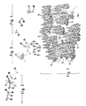
- the scenario according to FIG. 1 shows target objects 11 to be combated, such as armored vehicles, ammunition and fuel storage containers or heavy trucks, which, at least partially, under light natural (eg trees) or artificial (eg camouflaged protective structures) against direct view and attack from above. Protection 12 are stationed in combat or deployment positions.
- the indirect combating of such target objects 11 which are in the protected state by means of the introduced bomblet ammunition with downwardly oriented beam-forming explosive inlays is not very effective since, due to their function, these bomblets are detonated as soon as they strike the protected state.
- the beam-forming insert of the respective bomblet which is dimensioned for penetration into hard armor, only leads to minor destruction in the protective state and then no longer has any noteworthy effect in the target object underneath.
- target objects 11 of this type are protected in the protected state by means of warheads 18 which are specially designed for this purpose and which are moved in a conventional manner by means of a carrier 13 - for example a ballistic projectile, but preferably a rocket (FIG. 2) - over a previously cleared target area 14 .
- the ogives 16 and parts of the casing 17 are blown off pyrotechnically there by a time-controlled or remote-controlled igniter 15.
- the warhead 18 is released from the carrier 13, which then crashes steeply due to its ballistically less favorable geometry and center of gravity.
- the warhead 18 (Fig. 2) can be one or more elongated cylindrical structures (Fig.
- warheads 18 ' hereinafter referred to as one-piece warheads 18 '
- one or more stacks of short-cylindrical active bodies (submunitions 20; Fig . 3) made from sleeve-like Distribution units 19 are spread.
- it is a shipment corresponding to that of the MLRS 2 weapon system with an ejection device for AT-2 ground mines against hard-armored target objects.
- a gas generator 22 is initiated by the igniter 15, which inflates a hose 23 radially, which meanders on the inner wall of the casing 17 alternately along different sides of the almost caliber-filling warheads 18, which are otherwise positively fixed by plastic profile shells 24 'or respectively
- Distribution units 19 is guided along.
- Rigid feed pipes 25 serve as diametrical connections between the hoses 23 running on different sides and as a blow pipe following the gas generator 22, so as not to impede the radial spreading process by axial expansion stresses.
- Warheads 18 can also taper in the area that tapers forward of the carrier 13 can be accommodated. For manufacturing and logistical reasons, it is expedient to only have to provide cylindrical one-piece warheads 18 and distribution units 19 of the same diameter for this assembly.
- the foam profile shells 24 are therefore shaped and divided here so that they are fitted outside the carrier 13 around a central gas channel 26, and then the individual shell parts are glued to one another and thus completely ammunition inserted from the rear into the tapered casing 17 and to the Gas generator 22 can be connected.
- the radially inflatable tube 23 from the gas generator 22 for the radial ejection of the warheads 18 and possibly also for the radial breaking open of the casing 17 along its predetermined breaking points 21 runs in this example case (FIG. 6) around a central perforated gas channel 26 '.
- warheads 18 are designed as distribution units 19 for submunitions 20, they have a coaxially acting ejection device 27 (FIG. 8), which is designed like the gas generator 22 mentioned and emits with it, but via a deceleration set 28, during or as a result of ejection the carrier 13 is ignited to axially push the submunitions 20 out at the rear.
- a coaxially acting ejection device 27 (FIG. 8), which is designed like the gas generator 22 mentioned and emits with it, but via a deceleration set 28, during or as a result of ejection the carrier 13 is ignited to axially push the submunitions 20 out at the rear.
- the submunitions 20 (Fig. 3) or the integral warheads 18 '(Fig. 4) are equipped with a parachute or a ballut as an aerodynamic braking and aiming means 29 for the vertical alignment to the target area 14, which when released are pulled out of the envelope 17 or from the distribution unit 19 by the inflow effect of the surrounding medium from a packing space 30 and are stretched or inflated.
- This initiation can also take place via a self-disassembly circuit 38, which is also released by the linkage 31 via an active connection 39 and leads to the ignition of the explosive 37, if not within a predetermined period of time from the unfolding of the aerodynamic directional and braking means 29 via the plunger 32 a hard target impact is detected.
- a non-hard target impact does not result in the delivery of the ignition information 34. This ensures that the explosive 37 does not detonate when the artificial or natural protection 12 penetrates, because then the active charges of the warhead 18 'or its submunition 20 are too far above detonate the target objects 11 to be combated and would not produce a sufficient effect in them (see below).
- the discrimination between the breakdown of the protection 12 and the actual triggering of an ignition information 34 takes place by means of a response threshold 40 for the function of the plunger 32 or the sensor 33 influenced by it.
- This response threshold 40 can be an elastic, non-positive or positive locking, which is only possible with sufficient longitudinal stress of the plunger 32 opens and releases it for sensor influencing 33, but with lower longitudinal stress intercepts the plunger 32 resiliently and returns it to the starting position; as is known in detonator technology from the double-bolt delay sensor for unlocking.
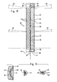
- FIG. 7 Another constructive solution for such a response threshold 40 is indicated in FIG. 7 by a thick rubber clamp, which is vulcanized radially between the plunger 32 and its telescopic housing 41 and only the plunger 32 for actuating the sensor 33 when the axial stress is sufficiently strong and long-lasting pulls out.
- a thick rubber clamp which is vulcanized radially between the plunger 32 and its telescopic housing 41 and only the plunger 32 for actuating the sensor 33 when the axial stress is sufficiently strong and long-lasting pulls out.
- the same effect can be achieved by installing a cylinder spring or a hydraulic throttle element.
- the direction of movement of the projectiles 45 formed from the wall 42 expediently experiences a splintering of one Angle a from the lower to the rear projectiles 45, so that a certain height range of the target object 11 (FIG. 9) is captured by the splinter fan 46.
- This splinter fan 46 can be caused by the fact that the transverse axes 47 experience a corresponding, increasing position with respect to the radial over the height of the wall 42. It is simpler in terms of production technology, however, to align all occupancy axes 47 parallel to one another, transversely to the axis of the wall 42, and to cause such detonation wave superimpositions by means of a relatively slow-burning concentric transfer charge 36 of great axial length (FIG. 10) that the projectile exit directions 48 (FIG. 11) increasingly stand out from the horizontal, the further the ignition progresses away from the front end 49.
- the braking means 29 for example a parachute gets caught in the protection 12 over the target object 11 (for example in the branches of a tree) (FIG. 12), so that the explosive 37 (FIG. 10) lacks a hard impact of the plunger 32 is not ignited.
- the splinter fan 42 is again triggered from deformed projectiles 45 with enclosed fire masses 44, but the effect in target objects 11 positioned underneath is due to the increasing splinter yarn angle a (FIG. 9 ) only slight.
- the explosive 37 is also provided on the rear side with a concentric transfer charge 36 ', which as a result of the detonation wave pressure build-up emanating from the opposite front end now has a splinter fan angle directed downwards from the horizontal b (Fig. 12) and still leads to the fight against target objects 11 - now diagonally from above.
- this oppositely oriented transfer charge 36 ' is ignited via a timer 50 which, like the self-dismantling circuit 38, is started by the application of force to the braking means linkage 31, but is designed for a shorter running time than the self-dismantling circuit 38.
- a separate self-dismantling circuit 38 can even be omitted by the transfer charge 36 'with the timer 50 simultaneously fulfilling this function.
- the warheads 18 'or the submunitions 20 can also be connected to the aerodynamic directional and braking means 29 via a particularly long distance rope 51.
- the rope length is then designed so that the typical protection 12, such as light canopies or trees, is penetrated by it; so that the braking means 29 has not yet sunk to the protection 12 when the ignition plunger 32 already strikes the target area 14 on firm ground and triggers the splinter angle a spread apart from the horizontal (as taken into account on the left in FIG. 12).
Abstract
Ein mittels eines Trägers (13) verbringbarer Gefechtskopf (18) soll dafür ausgelegt werden, eine wirksamere Bekämpfung von mittelhart bis hart gepanzerten Zielobjekten (11) unter leichtem natürlichem oder künstlichem Schutz (12) zu erbringen, als der herkömmliche Einsatz von mittels eines Geschosses oder einer Rakete verbrachten Hohlladungs-Bomblets. Dafür werden einteilige Gefechtsköpfe (18') oder in Verteileinheiten (19) untergebrachte Submunitionen (20) eingesetzt, deren Wandungen (42) projektilbildende Belegungen (43) mit Brandmassen-Hinterfütterung (44) aufweisen und die konstruktiv oder detonatorisch für einen gegenüber der Wandungs-Längsachse ansteigenden Splitterfächer (46) ausgelegt sind. Die Zündung erfolgt mittels eines herausklappbaren oder teleskopierbaren, abwärtsorientierten Stößels (32), der noch nicht beim Durchschlagen des Schutzes (12) auslöst, sondern erst beim harten Aufschlag im oder neben dem Zielobjekt (11). Sollte sich ein aerodynamisches Bremsmittel (29) eines einteiligen Gefechtskopfes (18') bzw. einer Submunition (20) im Schutz (12) verfangen, erfolgt eine Umorientierung des Splitterfächers (46) nach unten.A warhead (18) which can be brought about by means of a carrier (13) should be designed to provide a more effective control of medium-hard to hard-armored target objects (11) under light natural or artificial protection (12) than the conventional use of a projectile or a missile spent shaped charge bomblets. For this purpose, one-piece warheads (18 ') or submunitions (20) accommodated in distribution units (19) are used, the walls (42) of which have projectile-forming coverings (43) with fire-mass backing (44) and which are constructive or detonatory for one against the wall Splitter compartments (46) rising along the longitudinal axis are designed. The ignition takes place by means of a fold-out or telescopic, downward-oriented plunger (32), which does not trigger when the protection (12) breaks through, but only when it hits hard in or next to the target object (11). If an aerodynamic braking device (29) of a one-piece warhead (18 ') or a submunition (20) gets caught in the protection (12), the splinter compartment (46) is reoriented downwards.
Description
Die Erfindung betrifft einen Gefechtskopf gemäß dem Oberbegriff des Anspruches 1.The invention relates to a warhead according to the preamble of claim 1.
Derartige Gefechtsköpfe sind in der Form von Trägergeschossen für Bomblets mit strahlbildender Hohlladungs-Einlage (US-PS 44 88 488) oder als das Artillerieraketensystem MLRS-1 zur Bomblet-Verbringung über ein voraufgeklärtes Zielgebiet bekannt. Die Wirkung jedes einzelnen Bomblets beim Aufschlag auf ein mittelhart bis hart gepanzertes Zielobjekt ist zwar relativ gering; bei dichter Bomblet-Belegung des Zielgebietes ist jedoch eine Vielfach-Trefferwirkung in einem Zielobjekt mit entsprechend erhöhter Summenwirkung in Ziel zu erwarten.Warheads of this type are known in the form of carrier projectiles for bomblets with a beam-forming shaped charge insert (US Pat. No. 4,488,488) or as the artillery missile system MLRS-1 for moving bomblets over a pre-enlightened target area. The impact of every single bomblet on a medium-hard to hard-armored target is relatively small; with dense bomblet coverage of the target area, however, a multiple hit effect in a target object with a correspondingly increased total effect in the target can be expected.
Nachteilig an einem derartigen Gefechtskopf-Konzept ist insbesondere, daß die anzustrebende Vielfach-Wirkung eine sehr dichte Streuung der Bomblets über dem Zielgebiet bedingt, in dem die tatsächlich zu bekämpfenden Zielobjekte nur distanziert vorkommen. Die dichte Verbringung kann auch zu Fehlzündungen aufgrund von Bomblet-Kollisionen beim Abstieg ins Zielgebiet führen. Vor allem aber reduziert sich die Wirkung derartiger Bomblet-Gefechtsköpfe mit strahlbildender Hohlladung dann ganz drastisch, wenn der Einsatz gegen Zielobjekte im Schutzzustand erfolgt, also etwa gegen gepanzerte Fahrzeuge und Verkehrswege unter leichter natürlicher oder künstlicher Abdeckung wie Schutzdächern (DE-OS 33 37 115) oder Bäumen.A disadvantage of such a warhead concept is in particular that the desired multiple effect requires a very dense spreading of the bomblets over the target area, in which the target objects to be actually fought occur only at a distance. The dense movement can also cause misfires due to bomblet collisions when descending to the target area. Above all, however, the effect of such bomblet warheads with beam-forming hollow charge is reduced drastically if they are used against target objects in a protected state, e.g. against armored vehicles and traffic routes under light natural or artificial cover such as protective roofs (DE-OS 33 37 115). or trees.
Denn schon der leichte Lattenverschlag einer Tarneinrichtung oder das Geäst eines Baumes führt beim Aufschlag eines Bomblets mit strahlbildender Hohlladungs-Einlage zu dessen Initiierung und damit zu einem Verpuffen der munitionstechnischen Wirkung oberhalb des eigentlich interessierenden Zielobjektes.Even the slight slatted cradle of a camouflage device or the branches of a tree lead to the initiation of a bomblet with a beam-forming shaped charge insert and thus to a deflagration of the ammunition effect above the target object that is actually of interest.
Andererseits ist davon auszugehen, daß gegnerische Verbände sich in Ausgangs- und Bereitstellungsräumen auf ihren Einsatz vorbereiten, die durch Wälder, Zweckbauten von Ortschaften und Tarnmaßnahmen optimal gegen Aufklärungs-Einsichtnahme - und damit auch gegen die Wirkung herkömmlicher Bomblet-Munition - geschützt sind. Auch einsatzwichtige Massenverbrauchsgüter (wie Munition und Betriebsstoffe) können im Einsatzfalle nicht unter massiven Schutzbauten mitgeführt werden, sondern sie sind an feldmäßige Lagerstellen gebunden, für die soweit wie möglich der gegebene natürliche und der schnell errichtbare künstliche leichte Schutzzustand realisiert wird.On the other hand, it can be assumed that enemy associations are preparing for their deployment in exit and staging areas, which are optimally protected against inspection by reconnaissance - and thus also against the effects of conventional bomblet ammunition - through forests, functional buildings in villages and camouflage measures. Even essential mass consumer goods (such as ammunition and operating materials) cannot be carried under massive protective structures in the event of an emergency, but are tied to field-based storage locations, for which the given natural and quickly erectable artificial light protection status is achieved as far as possible.
In Erkenntnis dieser Gegebenheiten liegt der Erfindung die Aufgabe zugrunde, einen mittels eines Trägers wie insbesondere einer eingeführten Artillerierakete verbringbaren Gefechtskopf gattungsgemäßer Art zu schaffen, der eine größere Effektivität beim Einsatz gegen feindliche Zielobjekte im leichten Schutzzustand vorerwähnter Art verspricht.In recognition of these circumstances, the object of the invention is to create a warhead of the generic type which can be carried by means of a carrier such as, in particular, an introduced artillery rocket and which promises greater effectiveness when used against enemy target objects in the light protection state of the aforementioned type.
Diese Aufgabe wird erfindungsgemäß im wesentlichen dadurch gelöst, daß der gattungsgemäße Gefechtskopf nach dem Kennzeichnungsteil des Anspruches 1 ausgelegt ist.This object is essentially achieved in that the generic warhead is designed according to the characterizing part of claim 1.
Aus der US-PS 4 175 491 ist zwar bereits ein Gefechtskopf mit radialer projektilbildender Mantelflächen-Belegung, mit aerodynamischen Bremsmittel unt mit teleskopierbarem Auslöse-Stößel als solcher vorbekannt; dort wird aber durch gleichzeitige Zündung mehrerer individueller P-Ladungen mit entsprechender konstruktiver Anstellung gegenüber dem Lot auf die Mittellängsachse des Gefechtskopfes nur ein von der Horizontalen abwärts orientierter P-Ladungs-Splitterfächer hervorgerufen, was ganz erhebliche konstruktive und wirkungsmäßige Einschränkungen in Bezug auf die Längenauslegung des Gefechtskopfes und die Höhe der interessierenden Zielobjekte zur Folge hat. Im Schutzzustand stehende feindliche Zielobjekte würden von diesem vorbekannten Gefechtskopf also nur angegriffen werden können, wenn er beim Aufschlag auf den Schutz oberhalb des Zielobjektes zur Detonation gebracht wird - mit entsprechend geringer Wirkung im Ziel aufgrund der geringen Neigung der P-Splitter gegenüber der Horizontalen, weil die Zielobjekte erst in größerem Abstand (also erst durch womöglich dazwischen anzutreffende natürliche und künstliche Schutzvorrichtungen hindurch) und nur in flachem Winkel von oben getroffen werden können.From US Pat. No. 4,175,491, a warhead with radial projectile-forming lateral surface assignment, with aerodynamic braking means and with a telescopic trigger plunger, is already known as such; there, however, the simultaneous ignition of several individual P-charges with a corresponding constructive position relative to the plumb line on the central longitudinal axis of the warhead causes only one P-charge splinter fan oriented downwards from the horizontal, which results in very considerable constructive and effective restrictions with regard to the length of the Warhead and the height of the target objects of interest. Enemy targets in the state of protection would only be attacked by this previously known warhead if it was detonated when it hit the protection above the target - with correspondingly little effect in the target due to the low inclination of the P-splinters to the horizontal, because the target objects can only be hit at a greater distance (i.e. only through natural and artificial protective devices that may be found in between) and only at a flat angle from above.
Aus der US-PS 3 968 748 ist es für ein Bomblet eingangs erwähnter Art, also mit strahlbildender Hohlladungs-Einlage, bekannt, über einen teleskopierbaren Auslöse-Stößel die Dichte des Gegenstandes, auf den der Aufschlag erfolgt, auszuwerten; mit der Maßgabe, daß bei hartem Aufschlag (insbesondere auf ein hartgepanzertes Zielobjekt) unmittelbar die Zündung erfolgt, dagegen bei weichem Aufschlag (etwa auf weichen Untergrund) das Bomblet noch einmal zurückgeschleudert und erst in gewissem Abstand über dem Grund gezündet wird, um wenigstens noch eine radiale Splitterwirkung hervorzurufen. Ein derartiger Zündmechannismus ist gegen feindliche Objekte im Schutzzustand nicht erfolgversprechend einsetzbar, da der weiche Aufschlag auf den Schutz (etwa auf das Geäst von Bäumen oder auf die Abdeckung eines Unterstandes) nach dem Zurückspringen keine hinreichende Splitterwirkung im unter dem Schutz vorhandenen Zielobjekt erwarten läßt.From US Pat. No. 3,968,748 it is known for a bomblet of the type mentioned at the outset, that is to say with a beam-forming shaped charge insert, to evaluate the density of the object to which the impact is made by means of a telescopic trigger plunger; with the proviso that with a hard impact (especially on a hard-armored target object) the ignition takes place immediately, whereas with a soft impact (e.g. on a soft surface) the bomblet is thrown back again and is only fired at a certain distance above the ground, by at least one more to cause radial splintering. Such an ignition mechanism cannot be used promisingly against hostile objects in the protected state, since the soft impact on the protection (e.g. on the branches of trees or on the cover of a shelter) does not lead to a sufficient splintering effect in the target object present under the protection after the springing back.
Die erfindungsgemäße Lösung ist dagegen dafür ausgelegt, daß der Gefechtskopf - der als einteilig-integraler Gefechtskopf oder aufgeteilt auf Submunitionen ausgebildet sein kann - noch nicht beim Aufschlag auf den Schutz auslöst. Vielmehr wird der leichte Schutz zunächst durchbrochen, und erst der wesentlich härtere Aufschlag unmittelbar auf dem gepanzerten Zielobjekt bzw. auf hoch verdichteten oder gar betonierten Verkehrswegen führt zur Zündung eines nach oben aufgefächerten Splitterkegels, um in der Umgebung befindliche leicht bis mittelhart gepanzerte Objekte über ihre großen Seitenflächen mit den hochenergetischen P-Ladungs-Splittern anzugreifen.The solution according to the invention, on the other hand, is designed so that the warhead - which can be designed as a one-piece, integral warhead or divided into submunitions - does not yet trigger when it hits the protection. Rather, the light protection is first broken, and only the much harder impact directly on the armored target object or on highly compacted or even concreted traffic routes leads to the ignition of a splintered cone fanned out in order to lightly to moderately hard-armored objects in the area over their large ones Attack side surfaces with the high-energy P-charge splinters.
Im Gegensatz zu den Verhältnissen beim Einsatz von strahlbildenden Bomblets ist deshalb nun nicht mehr die möglichst dichte Belegung des Zielgebiets mit Bomblets erforderlich, um mehrere Treffer in einem einzigen Zielobjekt von oben erzielen. Deshalb können anstelle von Bomblet-Gefechtsköpfen nun auch vorteilhaft einteilig-integrale Gefechtsköpfe größerer Masse und größerer Anzahl an P-Ladungs-Belegungen eingesetzt werden; während andererseits aus dem Gefechtskopf verbrachte kleinere Submunitionen breiter gestreut werden können. Zweckmäßig ist deshalb eine Gefechtskopf-Ablieferung quer zur Flugrichtung des Verbringungs-Trägers in unterschiedlichen Richtungen, wofür integrale Gefechtsköpfe oder Bomblet-Verteileinheiten koaxial in schlanken Trägern (wie der MLRS-Rakete) oder aber in achsparalleler Packung in Trägern größeren Durchmessers (wie den Atacms-Raketen) verbracht werden können.In contrast to the situation when using beam-forming bomblets, it is therefore no longer necessary to cover the target area as densely as possible with bomblets in order to achieve multiple hits in a single target object from above. Therefore, instead of bomblet warheads, one-piece, integral warheads of greater mass and a greater number of P-charge assignments can now advantageously be used; while on the other hand, smaller submunitions brought out of the warhead can be spread more widely. It is therefore expedient to deliver the warhead transversely to the direction of flight of the delivery carrier in different directions, for which purpose integral warheads or bomblet distribution units coaxially in slim carriers (such as the MLRS rocket) or in axially parallel packing in carriers of larger diameter (such as the Atacms- Missiles) can be spent.
Die Wirkung im Ziel kann durch sekundäre Brandwirkung gesteigert werden, indem die P-Einlagen mit Brandmassen hinterfüttert werden, welche bei der Sprengstoff-Umformung der Einlage im Zentrum des Projektils eingeschlagen und so sicher ins Zielobjekt verbracht werden können. Dadurch ist die sekundäre Brandwirkung jedenfalls erheblicher, als beim Einsatz einer brennbaren Zusatzmasse im Zentrum einer strahlbildenden Hohlladungs-Einlage, wie sie aus der DE-OS 23 11 287 vorbekannt ist.The effect in the target can be increased by secondary fire action by backfilling the P-inserts with fire masses, which are hammered into the center of the projectile during the explosive shaping of the insert and can thus be safely brought to the target object. This is the secondary fire effect in any case considerably more than when using a combustible additional mass in the center of a beam-forming shaped charge insert, as is known from DE-OS 23 11 287.
Um zu vermeiden, daß die Gefechtsköpfe mit ihren aerodynamischen Ausricht- und Brems-Mitteln im Schutz hängen bleiben, wird zweckmäßigerweise eine hinreichend lange Distanzleine zwischen Bremsmittel und Gefechtskopf vorgesehen, so daß letzterer bereits zum Aufschlag im Zielgebiet führt, wenn das Bremsmittel, beispielsweise der Fallschirm, noch oberhalb des Schutzes, beispielsweise einer Baumkrone, schwebt. Stattdessen oder zusätzlich kann jedoch auch eine Umpolung der Anzündung dahingehend vorgesehen sein, daß der P-Ladungs-Splitterfächer dann von oben nach unten orientiert wird, wenn nach gewisser Zeitspanne ein Aufschlag im Zielgebiet nicht feststellbar ist, also augenscheinlich sich der Gefechtskopf beispielsweise im Geäst eines Baumes verfangen hat. Die damit ausgelöste Selbstzerlegung führt dann wenigstens noch zu einer Wirkung in der Umgebung der Zielobjekte.In order to avoid that the warheads get stuck in the protection with their aerodynamic alignment and braking means, it is advisable to provide a sufficiently long distance line between the braking means and the warhead, so that the latter already leads to the impact in the target area when the braking means, for example the parachute , still hovering above the protection, for example a tree crown. Instead of or in addition, however, the polarity of the ignition can be reversed so that the P-charge splinter fan is oriented from top to bottom if, after a certain period of time, an impact cannot be determined in the target area, i.e. the warhead is evident, for example, in the branches of one Tree has caught. The self-decomposition triggered by this then leads at least to an effect in the surroundings of the target objects.
Zusätzliche Alternativen und Weiterbildungen sowie weitere Merkmale und Vorteile der Erfindung ergeben sich aus den weiteren Ansprüchen und, auch unter Berücksichtigung der Darlegungen in der Zusammenfassung, aus nachstehender Beschreibung von in der Zeichnung unter Beschränkung auf das Wesentliche stark abstrahiert und nicht ganz maßstabsgerecht skizzierten bevorzugten Ausführungs- und Einsatzbeispielen zur erfindungsgemäßen Lösung. Es zeigt:
- Fig. 1 ein Beispiels-Szenario für zu bekämpfende Zielobjekte im natürlichen und künstlichen Schutzzustand,
- Fig. 2 die Raketen-Verbringung eines Gefechtskopfes zur Bekämpfung feindlicher Zielobjektes im Schutzzustand,
- Fig. 3 die Ablieferung von P-Padungs-Submunition aus einem Mehrfach-Gefechtskopf,
- Fig. 4 die Ablieferung eines Vollkaliber-Gefechtskopfes,
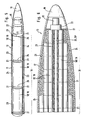
- Fig. 5 den Einbau mehrerer koaxialer Vollkaliber-Gefechtsköpfe gemäß Fig. 4 bzw. mehrerer angenähert kalibergleicher Verteileinheiten mit Submunitionen gemäß Fig. 3 in eine schlanke Artillerie-Rakete als Verbringungssystem,
- Fig. 6 den Einbau unterkalibriger Gefechtsköpfe bzw. Verteileinheiten in größerkalibrige taktische Gefechtsfeld-Raketen als Verbringungssystem,
- Fig. 7 eine P-Ladungs-Submunition gemäß Fig. 3 in detaillierterer Längsschnitt-Darstellung,
- Fig. 8 den Ausstoß von Submunitionen gemäß Fig. 3 in detaillierterer Darstellung,
- Fig. 9 den Wirkbereich der Submunition gemäß Fig. 3 bzw. Fig. 4,
- Fig. 10 in detaillierterer, teilweise geschnittener Darstellung einen Vollkaliber-Gefechtskopf gemäß Fig. 4,
- Fig. 11 den Umform- und Transportvorgang von mit Brandmasse hinterlegten P-Ladungen an den Gefechtsköpfen gemäß Fig. 3 bzw. Fig. 4
und - Fig. 12 Das Szenario zur Veranschaulichung umschaltbarer Wirkrichtungen bei einem Vollkaliber-Gefechtskopf gemäß Fig. 4.
- 1 shows an example scenario for target objects to be combated in the natural and artificial protection state,
- 2 shows the rocket movement of a warhead to combat enemy target objects in the protected state,
- 3 shows the delivery of P-Padungs submunitions from a multiple warhead,
- 4 shows the delivery of a full-caliber warhead,
- 5 shows the installation of several coaxial full-caliber warheads according to FIG. 4 or several approximately equal-caliber distribution units with submunitions according to FIG. 3 in a slim artillery missile as a delivery system,
- 6 the installation of sub-caliber warheads or distribution units in larger-caliber tactical battlefield missiles as a delivery system,
- 7 shows a P-charge submunition according to FIG. 3 in a more detailed longitudinal sectional illustration,
- 8 shows the release of submunitions according to FIG. 3 in more detail,
- 9 shows the effective range of the submunition according to FIG. 3 or FIG. 4,
- 10 in a more detailed, partially sectioned illustration, a full-caliber warhead according to FIG. 4,
- 11 shows the shaping and transport process of P-charges deposited with fire mass on the warheads according to FIG. 3 and FIG. 4
and - 12 shows the scenario for illustrating switchable directions of action in a full-caliber warhead according to FIG. 4.
Das Szenario gemäß Fig. 1 zeigt zu bekämpfende Zielobjekte 11 wie Panzerfahrzeuge, Munitions- und Treibstoff-Vorratsbehälter oder schwere Lastkraftwagen, die gegen direkte Sicht und Angriffs-Einwirkung von oben zumindest teilweise unter leichtem natürlichem (z.B. Bäume) oder künstlichem (z.B. getarnte Schutzbauten) Schutz 12 in Gefechts- oder Aufmarschstellung stationiert sind. Die indirekte Bekämpfung derartiger im Schutzzustand befindlicher Zielobjekte 11 mittels der eingeführten Bomblet-Munition mit nach unten-voraus orientierten strahlbildenden Sprengstoff-Einlagen ist wenig effektiv, da diese Bomblets funktionsbedingt bereits beim Aufschlag auf den Schutzzustand gezündet werden. Die auf Eindringen in harte Panzerung dimensionierte strahlbildende Einlage des jeweiligen Bomblets führt im Schutzzustand nur zu geringfügiger Zerstörung und im darunter stehenden Zielobjekt selbst dann zu keiner nennenswerten Wirkung mehr.The scenario according to FIG. 1 shows
Deshalb erfolgt gemäß vorliegender Erfindung die Bekämpfung derartiger Zielobjekte 11 im Schutzzustand mittels speziell dafür ausgelegter Gefechtsköpfe 18, die in herkömmlicher Weise mittels eines Trägers 13 - etwa eines ballistischen Lastengeschosses, vorzugsweise aber einer Rakete (Fig. 2) - über ein voraufgeklärtes Zielgebiet 14 verbracht werden. Durch einen zeitgesteuerten oder ferngesteuerten Zünder 15 werden dort die Ogive 16 und Teile der Hülle 17 pyrotechnisch abgesprengt. Dadurch wird der Gefechtskopf 18 aus dem Träger 13 freigegeben, der dann infolge seiner ballistisch ungünstigeren Geometrie und Schwerpunktsgegebenheiten steil abstürzt. Beim Gefechtskopf 18 (Fig. 2) kann es sich um einen oder mehrere gestreckt-zylindrische Gebilde (Fig. 4; nachstehend als einteilige Gefechtsköpfe 18′ bezeichnet) handeln, oder um einen oder mehrere Stapel von kurz-zylindrischen Wirkkörpern (Submunitionen 20; Fig. 3), die aus hülsenartigen Verteileinheiten 19 ausgestreut werden. Im letztgenannten Falle handelt es sich also um eine Verbringung entsprechend derjenigen des Waffensystems MLRS 2 mit Ausstoßeinrichtung für AT-2-Bodenminen gegen hart gepanzerte Zielobjekte.For this reason, according to the present invention, target objects 11 of this type are protected in the protected state by means of
Da die Wirkung der vorliegenden Gefechtsköpfe 18 nicht mehr auf dem Vielfach-Treffer durch Hohlladungsbomblets beruht, ist nun eine wesentlich breitere Zielflächenbedeckung möglich. Um it einem schlanken Träger 13 einen möglichst breiten Streubereich über dem Zielgebiet 14 zu erfassen, ist es zweckmäßig, gemäß der skizzenhaften Darstellung der Fig. 5 mehrere angenähert vollkalibrige einteilige Gefechtsköpfe 18′ und/oder Verteileinheiten 19 koaxial hintereinander in der längs Sollbruchstellen 21 aufsprengbaren Hülle 17 anzuordnen und aus dieser nicht nach vorne freizugeben (Fig. 2), sondern nach unterschiedlichen radialen Richtungen auszuwerfen. Dafür wird in diesem Beispielsfalle vom Zünder 15 ein Gasgenerator 22 initiiert, der einen Schlauch 23 radial aufbläht, welcher an der Innenwandung der Hülle 17 mäanderförmig-abwechselnd längs unterschiedlicher Seiten der fast kaliberfüllenden, im übrigen durch Kunststoff-Profilschalen 24 formschlüssig festgelegten Gefechtsköpfe 18′ bzw. Verteileinheiten 19 entlanggeführt ist. Als diametrale Verbindungen zwischen den an unterschiedlichen Seiten verlaufenden Schläuchen 23 sowie als Anblasrohr im Anschluß an den Gasgenerator 22 dienen starre Speise-Rohre 25, um den radialen Ausstreuvorgang nicht durch axiale Spreizbeanspruchungen zu behindern.Since the effect of the
Bei größerkalibrigem Träger 13 (Fig. 6) ist es im Interesse eines möglichst breiten Streufeldes von einteiligen oder mehrteiligen Gefechtsköpfen 18 zweckmäßiger, diese unterkalibrig zu dimensionieren und als mehrere achsparallele Stapel exzentrisch nebeneinander in der aufsprengbaren Hülle 17 anzuordnen (Fig. 6). Dabei können Gefechtsköpfe 18 auch im nach vorne konisch sich verjüngenden Bereich des Trägers 13 untergebracht werden. Aus fertigungstechnischen und logistischen Gründen ist es zweckmäßig, nur zylindrische einteilige Gefechtsköpfe 18 und Verteileinheiten 19 gleicher Durchmesser für diese Bestückung bereitstellen zu müssen. Die Schaumstoff-Profilschalen 24 sind deshalb hier so geformt und geteilt, daß sie außerhalb des Trägers 13 um einen zentralen Gaskanal 26 herum bestückt, und dann die einzelnen Schalenteile miteinander verklebt und so komplett munitioniert von rückwärts in die sich verjüngende Hülle 17 eingeschoben und an den Gasgenerator 22 angeschlossen werden können. Der vom Gasgenerator 22 radial aufblähbare Schlauch 23 zum radialen Auswerfen der Gefechtsköpfe 18 und gegebenenfalls auch zum radialen Aufbrechen der Hülle 17 längs ihrer Sollbruchstellen 21 verläuft in diesem Beispielsfalle (Fig. 6) um einen zentralen perforierten Gaskanal 26′ herum.In the case of a larger-caliber carrier 13 (FIG. 6), in the interest of the widest possible stray field of one-part or
Falls die Gefechtsköpfe 18 als Verteileinheiten 19 für Submunitionen 20 ausgelegt sind, weisen sie eine koaxial wirkende Auswurfeinrichtung 27 (Fig. 8) auf, die wie der erwähnte Gasgenerator 22 ausgelegt und mit diesem, aber über einen Verzögerungssatz 28, bei bzw. infolge Ausstoß aus dem Träger 13 gezündet wird, um die Submunitionen 20 heckseitig axial hinauszuschieben.If the
Die Submunitionen 20 (Fig. 3) bzw. die integralen Gefechtsköpfe 18′ (Fig. 4) sind mit einem Fallschirm oder einem Ballut als aerodynamischem Brems- und Richt-Mittel 29 für die vertikal auf das Zielgebiet 14 erfolgende Ausrichtung ausgestattet, die bei Freigabe aus der Hülle 17 bzw. aus der Verteileinheit 19 durch die Anströmwirkung des Umgebungsmediums aus einem Packraum 30 herausgezogen und aufgespannt bzw. aufgeblasen werden. Die dabei praktisch ruckartig auf Zug beanspruchte Anlenkung 31 dient als mechanische Auslöseeinrichtung zur Freigabe eines exzentrisch (Fig. 7) oder konzentrisch (Fig. 10) angeordneten, herausklappbaren und/oder teleskopartig herausfahrbaren Stößels 32 (vgl. GB 21 93 796), dessen Ausstellbewegung etwa durch Freigabe eines Federkraftspeichers oder durch Initiieren eines pyrotechnischen Kraftelementes (in der Zeichnung nicht weiter ausgeführt) durchgeführt werden kann und der in der ausgefahrenen Stellung verriegelt. Bei harter Axialbeanspruchung des ausgefahrenen Stößels 32, insbesondere infolge Aufschlags auf die Armierung eines zu bekämpfenden Zielobjektes 14, wird ein Sensor 33 (etwa eine mechanische Schaltstrecke) mechanisch angeregt, um eine Zündinformation 34 (Fig. 7) an eine Sicherungs- und Zündschaltung 35 zu liefern, aus der die Übertragungsladung 36 für das Anzünden des Sprengstoffes 37 initiiert wird. Diese Initiierung kann außerdem über eine Selbstzerlegerschaltung 38 erfolgen, die ebenfalls von der Anlenkung 31 über eine Wirkverbindung 39 freigegeben wird und zum Anzünden des Sprengstoffes 37 führt, wenn nicht innerhalb vorgegebener Zeitspanne ab Entfalten des aerodynamischen Richt- und Brems-Mittels 29 über den Stößel 32 ein harter Zielaufschlag detektiert wird.The submunitions 20 (Fig. 3) or the integral warheads 18 '(Fig. 4) are equipped with a parachute or a ballut as an aerodynamic braking and aiming means 29 for the vertical alignment to the
Ein nicht-harter Zielaufschlag dagegen führt nicht zur Abgabe der Zündinformation 34. Dadurch ist sichergestellt, daß noch nicht beim Durchschlagen des künstlichen oder natürlichen Schutzes 12 der Sprengstoff 37 detoniert, weil dann die Wirkladungen des Gefechtskopfes 18′ bzw. seiner Submunition 20 zu weit oberhalb der zu bekämpfenden Zielobjekte 11 detonieren und in diesen keine hinreichende Wirkung hervorrufen würden (vgl. unten). Die Diskrimination zwischen dem Durchschlagen des Schutzes 12 und dem tatsächlichen Auslösen einer Zündinformation 34 erfolgt mittels einer Ansprechschwelle 40 für die Funktion des Stößel 32 bzw. des von ihm beeinflußten Sensors 33. Diese Ansprechschwelle 40 kann eine elastische kraftschlüssige oder formschlüssige Arretierung sein, die erst bei hinreichender Längsbeanspruchung des Stößel 32 öffnet und ihn zur Sensor-Beeinflussung 33 freigibt, bei geringerer Längsbeanspruchung den Stößel 32 aber federnd abfängt und wieder in die Ausgangslage zurückführt; wie es in der Zündertechnik etwa vom Doppelbolzen-Verzögerungssensor für die Entsicherung bekannt ist.A non-hard target impact, on the other hand, does not result in the delivery of the
Als eine andere konstruktive Lösung für eine solche Ansprechschwelle 40 ist in Fig. 7 eine dicke Gummischelle angedeutet, die radial zwischen dem Stößel 32 und seinem Teleskopgehäuse 41 einvulkanisiert ist und erst bei hinreichend starker und lang-andauernder Axialbeanspruchung den Stößel 32 zur Betätigung des Sensors 33 ausreißen läßt. Die gleiche Wirkung läßt sich durch Einbau einer Zylinderfeder oder eines hydraulischen Drosselelementes erzielen.Another constructive solution for such a
Wenn also der in seiner ausgefahrenen Stellung verriegelte Stößel 32 - gegebenenfalls nach Durchschlagen des Schutzes 12 in Form von dünnen Ästen oder Abdeckplanen - auf den dagegen festeren Untergrund im Zielgebiet 14 aufschlägt (Fig. 9), wird wie beschrieben der Sprengstoff 37 gezündet, der innerhalb einer hohlzylindrischen Wandung 42 verdämmt ist. Die weist eine Anzahl von axial und peripher gegeneinander versetzten konkaven Einbuchtungen auf, welche als kugelkappenförmige Hohlladungs-Belegungen 43 ausgelegt und an ihrer konvexen Innenmantelfläche mit einer Brandmasse 44 hinterfüttert sind (Fig. 1̇1̇). Der vom gezündeten Sprengstoff 37 hervorgerufene Umformvorgang (Fig. 11) zum radial bezüglich der Wandung 42 beschleunigten Projektil 45 führt dazu, daß die Brandmasse 44 ins Innere des Projektils 45 eingefaltet und dadurch beim Ziel-Einschlag ins Innere des Zielobjekts 11 eingeführt wird, wo durch die Einschlagwirkung eine Ergänzung durch sekundäre Brandwirkungen erfährt, beispielsweise um Munitionsvorräte oder Treibstoffvorräte zu entzünden.So if the
Da die Wahrscheinlichkeit größer ist, daß der Auslöse-Aufschlag des Stößels 32 nicht auf einem sondern neben einem Zielobjekt 11 im Zielgebiet 14 erfolgt (Fig. 9), erfährt die Bewegungsrichtung der aus der Wandung 42 umgeformten Projektile 45 zweckmäßigerweise eine Splitter-Auffächerung um einen Winkel a von den unteren zu den rückwärtigen Projektilen 45, so daß ein gewisser Höhenbereich des Zielobjektes 11 (Fig. 9) vom Splitterfächer 46 erfaßt wird.Since the probability of the
Dieser Splitterfächer 46 kann dadurch hervorgerufen sein, daß die Querachsen 47 über die Höhe der Wandung 42 eine entsprechende, zunehmende Anstellung gegenüber der Radialen erfahren. Fertigungstechnisch einfacher ist es jedoch, alle Belegungs-Achsen 47 zueinander parallel, quer zur Achse der Wandung 42, auszurichten und durch eine relativ langsam abbrennende konzentrische Übertragungsladung 36 großer axialer Länge (Fig. 10) derartige Detonationswellen-Überlagerungen hervorzurufen, daß die Projektil-Abgangsrichtungen 48 (Fig. 11) sich zunehmend gegenüber der Horizontalen abheben, je weiter die Zündung von dem vorderen Stirnende 49 weg fortschreitet.This
Grundsätzlich kann nicht ausgeschlossen werden, daß das Bremsmittel 29 (etwa ein Fallschirm) sich im Schutz 12 über dem Zielobjekt 11 (etwa im Geäst eines Baumes) verfängt (Fig. 12), so daß der Sprengstoff 37 (Fig. 10) mangels harten Aufschlags des Stößels 32 nicht gezündet wird. Wenn dann nach Ablauf der vorgegebenen Zeitspanne die Selbstzerlegerschaltung 38 in Funktion tritt, wird zwar wieder der Splitterfächer 42 aus umgeformten Projektilen 45 mit eingeschlossenen Brandmassen 44 ausgelöst, aber die Wirkung in darunter positionierten Zielobjekten 11 ist wegen des ansteigenden Splittergarben-Winkels a (Fig. 9) nur gering. Um dennoch auch in diesem Falle eine Wirkung im Zielobjekt 11 zu erzielen, kann vorgesehen sein, den Sprengstoff 37 auch heckseitig mit einer konzentrischen Übertragungsladung 36′ auszustatten, die infolge des vom gegenüberliegenden Stirnende ausgehenden Detonationswellen-Druckaufbaus nun einen von der Horizontalen nach unten gerichteten Splitterfächerwinkel b (Fig. 12) hervorruft und so doch noch zur Bekämpfung von Zielobjekten 11 - jetzt schräg von oben - führt. Dafür wird diese entgegengesetzt orientierte Übertragungsladung 36′ über einen Zeitzünder 50 angezündet, der wie die Selbstzerlegerschaltung 38 von der Kraftbeaufschlagung der Bremsmittel-Anlenkung 31 gestartet wird aber auf kürzere Laufzeit als die Selbstzerlegerschaltung 38 ausgelegt ist. Eine gesonderte Selbstzerlegerschaltung 38 kann sogar entfallen, indem die Übertragungsladung 36′ mit Zeitzünder 50 diese Funktion gleichzeitig mit erfüllen.In principle, it cannot be excluded that the braking means 29 (for example a parachute) gets caught in the
Stattdessen oder zusätzlich können die Gefechtsköpfe 18′ bzw. die Submunitionen 20 aber auch über ein besonders langes Distanzseil 51 an das aerodynamische Richt- und Brems-Mittel 29 angeschlossen sein. Die Seillänge ist dann so ausgelegt, daß der typische Schutz 12 wie etwa von leichten Schutzdächern oder Bäumen davon durchragt wird; so daß das Bremsmittel 29 noch nicht bis auf den Schutz 12 abgesunken ist, wenn der Zünd-Stößel 32 bereits auf festen Grund im Zielgebiet 14 aufschlägt und den von der Horizontalen nach oben gespreizten Splitterwinkel a auslöst (wie in Fig. 12 links berücksichtigt).Instead or in addition, the warheads 18 'or the
Claims (8)
dadurch gekennzeichnet,
daß die Wandungs-Belegungen (43) für einen von unten nach oben ansteigenden Splitterwinkel (a) ihrer Projektil-Flugrichtungen (48) ausgelegt sind und der Stößel (32) mit einer Ansprechschwelle (40) ausgestattet ist, die nur bei relativ hartem Aufschlag zur Auslösung der Zündinformation (34) führt.1. By means of a carrier (13) bringable warhead (18, 18 '; 19/20) with aerodynamic alignment and braking means (29) and oriented impact ram (32) for triggering ignition information (34) for the a hollow cylindrical wall (42) with flat concave coverings (43) insulated explosives (37),
characterized,
that the wall coverings (43) are designed for a splinter angle (a) rising from the bottom of their projectile flight directions (48) and the plunger (32) is equipped with a response threshold (40) which is only available when the impact is relatively hard Triggering the ignition information (34) leads.
dadurch gekennzeichnet,
daß er mit Verteileinheiten (19) für axial relativ kurzbauende Submunitionen (20) ausgestattet ist, die jede mit konstruktiv angestellten Belegungen (43) zur Ausbildung des Splitterfächerwinkels (a) ausgestattet sind.2. warhead according to claim 1,
characterized,
that it is equipped with distribution units (19) for axially relatively short submunitions (20), each of which is equipped with design-related assignments (43) to form the splitter fan angle (a).
dadurch gekennzeichnet,
daß er als einteilig-integraler Gefechtskopf (18′) mit quer zu dessen Längsachse orientierten Belegungen (43) ausgelegt ist, die ihren Splitterfächerwinkel (a) durch von der Stirnseite fortschreitenden Abbrand einer koaxial im Sprengstoff (37) angeordneten Übertragungsladung (36) erfahren.3. warhead according to claim 1,
characterized,
that it is designed as a one-piece integral warhead (18 ') with transversely to the longitudinal axis oriented coatings (43), which experience their splinter fan angle (a) by progressive combustion from the end face of a coaxial in the explosive (37) arranged transfer charge (36).
dadurch gekennzeichnet,
daß er mit einer Zeitzünderfunktion für Anzündung einer von der entgegengesetzten Stirnfläche her abbrennenden Übertragungsladung (36) ausgelegt ist, um einen abwärtsorientierten Splitterfächerwinkel (b) zu erzielen.4. warhead according to claim 3,
characterized,
that it is designed with a timer function for igniting a transfer charge (36) burning off from the opposite end face in order to achieve a downward-oriented splinter fan angle (b).
dadurch gekennzeichnet,
daß seine Wandungs-Belegungen (43) durch eine Brandmasse (44) hinterfüttert sind.Warhead according to one of the preceding claims,
characterized,
that its wall coverings (43) are backed by a fire mass (44).
dadurch gekennzeichnet,
daß er bzw. seine Submunition (20) über ein sehr langes Distanzseil (51) am aerodynamischen Ausricht- und Brems-Mittel (29) aufgehängt ist.6. warhead according to any one of the preceding claims,
characterized,
that he or his submunition (20) is suspended from the aerodynamic alignment and braking means (29) via a very long distance rope (51).
dadurch gekennzeichnet,
daß er aus mehreren koaxial im Träger (13) angeordneten Teilen besteht, die durch mäandrisch verlaufende Aufblas-Schläuche (23) nach unterschiedlichen Richtungen radial aus dem Träger (13) auswerfbar sind.7. warhead according to any one of the preceding claims,
characterized,
that it consists of several parts arranged coaxially in the carrier (13), which can be ejected radially from the carrier (13) in different directions by meandering inflation hoses (23).
dadurch gekennzeichnet,
daß er aus mehreren Teilen besteht, die in axialer und paralleler Stapelung in Kunststoff-Profilschalen (24) eingefaßt und in der Träger-Hülle (17) gehaltert sind.8. warhead according to one of claims 1 to 6,
characterized,
that it consists of several parts, which are enclosed in axial and parallel stacking in plastic profile shells (24) and are held in the carrier shell (17).
Applications Claiming Priority (2)
| Application Number | Priority Date | Filing Date | Title |
|---|---|---|---|
| DE3823823A DE3823823A1 (en) | 1988-07-14 | 1988-07-14 | SKULL HEAD |
| DE3823823 | 1988-07-14 |
Publications (2)
| Publication Number | Publication Date |
|---|---|
| EP0350821A2 true EP0350821A2 (en) | 1990-01-17 |
| EP0350821A3 EP0350821A3 (en) | 1990-09-05 |
Family
ID=6358628
Family Applications (1)
| Application Number | Title | Priority Date | Filing Date |
|---|---|---|---|
| EP19890112531 Withdrawn EP0350821A3 (en) | 1988-07-14 | 1989-07-08 | War head |
Country Status (3)
| Country | Link |
|---|---|
| US (1) | US4974515A (en) |
| EP (1) | EP0350821A3 (en) |
| DE (1) | DE3823823A1 (en) |
Cited By (3)
| Publication number | Priority date | Publication date | Assignee | Title |
|---|---|---|---|---|
| EP0539340A2 (en) * | 1991-10-23 | 1993-04-28 | Bofors AB | Launching system for a submunition |
| WO2008145259A1 (en) | 2007-05-30 | 2008-12-04 | Rheinmetall Waffe Munition Gmbh | Warhead |
| WO2012104015A3 (en) * | 2011-02-02 | 2012-09-27 | Rheinmetall Waffe Munition Gmbh | Explosive projectile |
Families Citing this family (14)
| Publication number | Priority date | Publication date | Assignee | Title |
|---|---|---|---|---|
| DE4014292C2 (en) * | 1990-05-04 | 1993-12-16 | Deutsche Aerospace | Dispenser for the transport and discharge of cluster munitions |
| US5191169A (en) * | 1991-12-23 | 1993-03-02 | Olin Corporation | Multiple EFP cluster module warhead |
| DE4210931C1 (en) * | 1992-04-02 | 2000-05-11 | Daimlerchrysler Aerospace Ag | Fragmentation warhead with pre-formed fragments, in which fragments are made of ductile material and are dish-shaped in direction from main charge |
| DE29507361U1 (en) * | 1995-05-08 | 1996-09-26 | Diehl Gmbh & Co | Submunition |
| FR2740212B1 (en) * | 1995-10-20 | 1997-12-05 | Giat Ind Sa | EXPLOSIVE CHARGE GENERATOR OF CORE |
| US5619008A (en) * | 1996-03-08 | 1997-04-08 | Western Atlas International, Inc. | High density perforating system |
| DE10065816B4 (en) * | 2000-12-27 | 2009-04-23 | Buck Neue Technologien Gmbh | Ammunition for generating a fog |
| FR2866701A1 (en) | 2004-02-20 | 2005-08-26 | Giat Ind Sa | Multiple-core shaped charge, has elementary charges with their axes forming angle with axis of shaped charge or parallel to axis of shaped charge, where elementary charges are initiated by same initiation unit having single detonator |
| SE541040C2 (en) * | 2008-01-29 | 2019-03-12 | Bae Systems Bofors Ab | Grenade with multiple impact loads and procedure therefore |
| US8536500B2 (en) * | 2008-08-07 | 2013-09-17 | Cpi Ip, Llc | System and method for rapid aiming and firing of defensive countermeasures |
| RU2600017C1 (en) * | 2015-05-28 | 2016-10-20 | Акционерное общество "Конструкторское бюро приборостроения им. академика А.Г. Шипунова" | Axially symmetric initiation assembly with cumulative funnel of warhead |
| US10508892B1 (en) * | 2016-08-15 | 2019-12-17 | The United States Of America As Represented By The Secretary Of The Navy | Distributed fuze architecture for highly reliable submunitions |
| SE545173C2 (en) | 2017-11-28 | 2023-05-02 | Bae Systems Bofors Ab | Spin stabilized projectile and method for providing a horizontal dispersion pattern |
| DE102018129786B4 (en) * | 2018-11-26 | 2022-03-03 | Rheinmetall Waffe Munition Gmbh | Test and/or practice ammunition |
Citations (8)
| Publication number | Priority date | Publication date | Assignee | Title |
|---|---|---|---|---|
| FR1354270A (en) * | 1963-01-24 | 1964-03-06 | Soc Tech De Rech Ind | Improvements to the initiation of explosive devices with focused peripheral effects |
| DE1478009B1 (en) * | 1963-01-24 | 1972-07-13 | Tech De Rech S Ind & Mecanique | Ignition system for a warhead |
| US3769911A (en) * | 1971-12-14 | 1973-11-06 | Atomic Energy Commission | Contact fuse |
| FR2315679A1 (en) * | 1975-06-25 | 1977-01-21 | Serat | Explosive charge with wounding effect - has hollow peripheral cladding of semi-toroidal section centred on lengthwise axis |
| US4175491A (en) * | 1966-10-08 | 1979-11-27 | Messerschmitt-Bolkow-Blohm Gesellschaft Mit Beschrankter Haftung | Warhead and anti-tank missile construction |
| DE2807280A1 (en) * | 1978-02-21 | 1982-08-19 | Messerschmitt-Bölkow-Blohm GmbH, 8000 München | Explosive charge for warheads or cluster mines - has prefab. splinters at rear of case for affecting various targets |
| FR2568366A1 (en) * | 1984-07-26 | 1986-01-31 | Serat | DEPLOYABLE TELESCOPIC HEADPHONES FOR MACHINERY, PROJECTILES, BOMBS OR MISSILES |
| DE2807309C1 (en) * | 1978-02-21 | 1987-07-23 | Messerschmitt Boelkow Blohm | Explosive charge with spiked or projectile-forming assignments |
Family Cites Families (18)
| Publication number | Priority date | Publication date | Assignee | Title |
|---|---|---|---|---|
| US2725011A (en) * | 1952-04-04 | 1955-11-29 | James A Sundermann | Base self-destruction fuze for ordnance projectiles |
| FR1092563A (en) * | 1953-10-30 | 1955-04-22 | Soc Tech De Rech Ind | Improvements to offensive apparatus |
| US3145656A (en) * | 1959-08-14 | 1964-08-25 | Melvin A Cook | Explosive warhead |
| US3633510A (en) * | 1970-08-05 | 1972-01-11 | Us Navy | Dual mode fuze explosive train |
| US3968748A (en) * | 1973-01-15 | 1976-07-13 | The United States Of America As Represented By The Secretary Of The Navy | Target discriminating bomblet |
| DE2306872A1 (en) * | 1973-02-13 | 1974-08-15 | Hans Loeckmann | Explosives article containing pyrometal - spec. (H enriched) palladium, for promoting ignition |
| US3913488A (en) * | 1973-09-17 | 1975-10-21 | Us Army | Ballistic disc |
| FR2287027A1 (en) * | 1974-10-04 | 1976-04-30 | Alary Patrice | System for increasing bomb blast effect - uses conical section grooves in casing to concentrate action in particular plane |
| DE3111907A1 (en) * | 1981-03-26 | 1982-10-07 | Dynamit Nobel Ag, 5210 Troisdorf | METHOD FOR DISTRIBUTING SUBMUNITION |
| US4458596A (en) * | 1982-07-06 | 1984-07-10 | The United States Of America As Represented By The Secretary Of The Navy | Multi-purpose bomblet |
| IT8349126A0 (en) * | 1982-10-13 | 1983-10-07 | Secr Defence Brit | PROTECTIVE SHELL AGAINST BALLISTIC PROJECTILES |
| US4488488A (en) * | 1982-12-23 | 1984-12-18 | The United States Of America As Represented By The Secretary Of The Army | Warhead safety and ribbon chute holder |
| DE3326877A1 (en) * | 1983-07-26 | 1985-02-07 | Diehl GmbH & Co, 8500 Nürnberg | Method and device for combating targets by means of submunition ejected above a target zone |
| DE3525147C1 (en) * | 1985-07-13 | 1987-01-15 | Diehl Gmbh & Co | Fall missile to combat radar positions in particular |
| DE3540219A1 (en) * | 1985-11-13 | 1987-05-14 | Diehl Gmbh & Co | Carrier projectile for submunitions |
| DE3623128A1 (en) * | 1986-07-09 | 1988-01-28 | Diehl Gmbh & Co | SUBMUNITION |
| US4853059A (en) * | 1986-12-24 | 1989-08-01 | Baxter International Inc. | Apparatus and process for manufacturing cuvetter belts |
| US4714020A (en) * | 1987-01-30 | 1987-12-22 | Honeywell Inc. | Enabling device for a gas generator of a forced dispersion munitions dispenser |
-
1988
- 1988-07-14 DE DE3823823A patent/DE3823823A1/en not_active Withdrawn
-
1989
- 1989-07-08 EP EP19890112531 patent/EP0350821A3/en not_active Withdrawn
- 1989-07-13 US US07/379,490 patent/US4974515A/en not_active Expired - Fee Related
Patent Citations (8)
| Publication number | Priority date | Publication date | Assignee | Title |
|---|---|---|---|---|
| FR1354270A (en) * | 1963-01-24 | 1964-03-06 | Soc Tech De Rech Ind | Improvements to the initiation of explosive devices with focused peripheral effects |
| DE1478009B1 (en) * | 1963-01-24 | 1972-07-13 | Tech De Rech S Ind & Mecanique | Ignition system for a warhead |
| US4175491A (en) * | 1966-10-08 | 1979-11-27 | Messerschmitt-Bolkow-Blohm Gesellschaft Mit Beschrankter Haftung | Warhead and anti-tank missile construction |
| US3769911A (en) * | 1971-12-14 | 1973-11-06 | Atomic Energy Commission | Contact fuse |
| FR2315679A1 (en) * | 1975-06-25 | 1977-01-21 | Serat | Explosive charge with wounding effect - has hollow peripheral cladding of semi-toroidal section centred on lengthwise axis |
| DE2807280A1 (en) * | 1978-02-21 | 1982-08-19 | Messerschmitt-Bölkow-Blohm GmbH, 8000 München | Explosive charge for warheads or cluster mines - has prefab. splinters at rear of case for affecting various targets |
| DE2807309C1 (en) * | 1978-02-21 | 1987-07-23 | Messerschmitt Boelkow Blohm | Explosive charge with spiked or projectile-forming assignments |
| FR2568366A1 (en) * | 1984-07-26 | 1986-01-31 | Serat | DEPLOYABLE TELESCOPIC HEADPHONES FOR MACHINERY, PROJECTILES, BOMBS OR MISSILES |
Cited By (6)
| Publication number | Priority date | Publication date | Assignee | Title |
|---|---|---|---|---|
| EP0539340A2 (en) * | 1991-10-23 | 1993-04-28 | Bofors AB | Launching system for a submunition |
| EP0539340A3 (en) * | 1991-10-23 | 1993-12-22 | Bofors Ab | Launching system for a submunition |
| WO2008145259A1 (en) | 2007-05-30 | 2008-12-04 | Rheinmetall Waffe Munition Gmbh | Warhead |
| AU2008255286B2 (en) * | 2007-05-30 | 2012-07-05 | Rheinmetall Waffe Munition Gmbh | Warhead |
| US8528480B2 (en) | 2007-05-30 | 2013-09-10 | Rheinmetall Waffe Munition Gmbh | Warhead |
| WO2012104015A3 (en) * | 2011-02-02 | 2012-09-27 | Rheinmetall Waffe Munition Gmbh | Explosive projectile |
Also Published As
| Publication number | Publication date |
|---|---|
| US4974515A (en) | 1990-12-04 |
| DE3823823A1 (en) | 1990-01-18 |
| EP0350821A3 (en) | 1990-09-05 |
Similar Documents
| Publication | Publication Date | Title |
|---|---|---|
| US4922826A (en) | Active component of submunition, as well as flechette warhead and flechettes therefor | |
| US6688032B1 (en) | Rifle-launched non-lethal cargo dispenser | |
| US3332348A (en) | Non-lethal method and means for delivering incapacitating agents | |
| EP0583642B1 (en) | Warhead with tandem charge | |
| US3855933A (en) | Dual purpose grenade | |
| US5988071A (en) | Penetrator having multiple impact segments, including an explosive segment | |
| RU2293281C2 (en) | Missile for throwing charges and modes of its using | |
| EP0350821A2 (en) | War head | |
| US20160223309A1 (en) | Weapon and Weapon System Employing the Same | |
| EA006030B1 (en) | Projectile having a high penetrating action and lateral action equipped with an integrated fracturing device | |
| DE19617221A1 (en) | Projectile, e.g. a mortar, for use against armoured vehicles or bunkers | |
| EP0742421A1 (en) | Fragmentation type submunition carried by a parachute | |
| US4854240A (en) | Two-stage shaped charge projectile | |
| DE19601756C1 (en) | Method, for projecting armored object from projectiles, involves shooting grenade against projectile and igniting war head of grenade if shock wave of war head is behind center of mass f projectile | |
| DE3515497A1 (en) | ARMOR DEVICE MINE | |
| EP0298494B1 (en) | Active sub-munition part, and flechette warhead and flechettes therefor | |
| RU2158408C1 (en) | Method and device (ammunition) for destruction of ground and air targets | |
| KR102041828B1 (en) | Projectile having high explosive and submunition | |
| DE3920016C2 (en) | ||
| DE4034618C2 (en) | mine | |
| RU2237233C1 (en) | Cluster shell with fragmentation-cluster projecting unit "simarga" | |
| CA2251076A1 (en) | Countermeasure apparatus for deploying interceptor elements from a spin stabilized rocket | |
| RU2758282C1 (en) | Projectile for combating unmanned aircraft | |
| EP0961098A2 (en) | Carrier projectile with submunitions and method for attacking a target with these submunitions | |
| US1335406A (en) | Projectile |
Legal Events
| Date | Code | Title | Description |
|---|---|---|---|
| PUAI | Public reference made under article 153(3) epc to a published international application that has entered the european phase |
Free format text: ORIGINAL CODE: 0009012 |
|
| AK | Designated contracting states |
Kind code of ref document: A2 Designated state(s): DE FR GB IT |
|
| 17P | Request for examination filed |
Effective date: 19900328 |
|
| PUAL | Search report despatched |
Free format text: ORIGINAL CODE: 0009013 |
|
| AK | Designated contracting states |
Kind code of ref document: A3 Designated state(s): DE FR GB IT |
|
| 17Q | First examination report despatched |
Effective date: 19911227 |
|
| STAA | Information on the status of an ep patent application or granted ep patent |
Free format text: STATUS: THE APPLICATION IS DEEMED TO BE WITHDRAWN |
|
| 18D | Application deemed to be withdrawn |
Effective date: 19930216 |