US8523751B2 - Endless screw of a centrifuge with ceramic wear plates - Google Patents
Endless screw of a centrifuge with ceramic wear plates Download PDFInfo
- Publication number
- US8523751B2 US8523751B2 US12/518,802 US51880207A US8523751B2 US 8523751 B2 US8523751 B2 US 8523751B2 US 51880207 A US51880207 A US 51880207A US 8523751 B2 US8523751 B2 US 8523751B2
- Authority
- US
- United States
- Prior art keywords
- endless screw
- centrifuge
- supporting parts
- thin ceramic
- ceramic plates
- Prior art date
- Legal status (The legal status is an assumption and is not a legal conclusion. Google has not performed a legal analysis and makes no representation as to the accuracy of the status listed.)
- Active, expires
Links
Images


Classifications
-
- B—PERFORMING OPERATIONS; TRANSPORTING
- B04—CENTRIFUGAL APPARATUS OR MACHINES FOR CARRYING-OUT PHYSICAL OR CHEMICAL PROCESSES
- B04B—CENTRIFUGES
- B04B1/00—Centrifuges with rotary bowls provided with solid jackets for separating predominantly liquid mixtures with or without solid particles
- B04B1/20—Centrifuges with rotary bowls provided with solid jackets for separating predominantly liquid mixtures with or without solid particles discharging solid particles from the bowl by a conveying screw coaxial with the bowl axis and rotating relatively to the bowl
- B04B1/2008—Centrifuges with rotary bowls provided with solid jackets for separating predominantly liquid mixtures with or without solid particles discharging solid particles from the bowl by a conveying screw coaxial with the bowl axis and rotating relatively to the bowl with an abrasion-resistant conveyor or drum
Definitions
- the invention relates to an endless screw of a centrifuge for discharging centrifuged material from a centrifuge, wherein a series of thin ceramic plates are fastened next to one another on the outer edge of the endless screw.
- This object is achieved according to the invention in that at least two integrally formed ceramic projections, in particular ceramic pins, protrude from the thin ceramic plates and are located, on one or both side surfaces of the endless screw edge, in recesses which are shaped in a manner corresponding to the projections/pins.
- the thin ceramic plates have at least two recesses in which are located integrally formed projections, in particular metal pins, which protrude from a side surface of the endless screw edge and are shaped in a manner corresponding to the recesses.
- Such embodiments result in the thin ceramic plates being fastened with a secure form-fitting connection, with production and fastening being particularly simple. Reliable determination of the position of the thin plates is also made possible. Thin ceramic plates with recesses can be produced in a simpler manner. A greater resistance to breaking is achieved in relation to severe shearing stresses. The thin plates can also then be produced more easily from other wear-resistant materials.
- the fastening is particularly simple if the projections and the corresponding recesses have a round cross section. However, as an alternative, they may also be non-round, in particular rectangular or square in cross section.
- the thin ceramic plates can be adhesively bonded to the supporting parts, in particular precision castings. It is also advantageous in this case if thin ceramic plates are fastened on both sides of the supporting parts, in particular of the precision castings.
- the wear is further substantially reduced and the useful life increased if, at the end facing away from the outer endless screw edge, the thin ceramic plates form a projecting surface which covers the endless screw surface on the outside in order to protect, by covering, the weld seam for fastening the supporting parts.
- a lower degree of wear of the supporting parts is achieved if the sides or side edges of the supporting parts, with which they are in contact with adjacent supporting parts, are shaped obliquely and/or in a step-shaped manner in order to be in contact with one another in a form-fitting and tight manner.
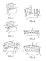
- FIGS. 1 to 6 show perspectively illustrated cutouts of the outer edge of an endless screw of a centrifuge with thin ceramic plates fastened on one side;
- FIGS. 7 and 8 show perspective illustrations of thin ceramic plates fastened on both sides of the centrifuge edge
- FIG. 9 shows a section through the centrifuge edge
- FIG. 10 shows a thin ceramic plate
- FIG. 11 shows a supporting part which can be fastened to the endless screw edge
- FIG. 12 shows views of the supporting parts from two sides and in top view
- FIGS. 13 to 18 correspond to FIGS. 1 to 5 with the difference that the supporting parts have projections and the thin ceramic plates have corresponding recesses.
- the helix of an endless screw of a centrifuge 1 has an outer edge 2 on which outwardly protruding, rectangular, in particular thin-plate-like supporting parts 3 , preferably made from precision casting, are fastened, in particular welded.
- the endless screw of a centrifuge 1 and the helix thereof are preferably composed of steel.
- the supporting parts 3 which protrude radially outward each have two bores as recesses 4 which are arranged radially one above the other.
- Elongate, rectangular thin ceramic plates 5 are fastened to the supporting parts 3 and cover the supporting parts.
- Projecting, pin-shaped projections 6 are arranged and integrally formed radially one above another on the thin ceramic plates 5 , the size and dimensions of which projections correspond to those of the recesses 4 , and therefore the thin ceramic plates 5 can be fastened laterally to the supporting parts 3 in a form-fitting manner.
- the supporting parts 3 each form a step 3 b in the region of their foot, and therefore the foot 3 a which is fastened to the outer edge 2 has a greater thickness D than the thickness of the adjoining outer region of the supporting part 3 .
- Said step 3 b is covered by a step 6 b of the thin plate 5 , with the thin ceramic plates forming, adjacent to the step 6 a , a projecting surface 7 which projects toward the axis of the endless screw and projects toward the axis to such an extent that it projects over the endless screw surface or the helical surface and therefore also the outer edge 2 in order to protect said region optimally against wear.
- the supporting parts 3 which support the thin plates 5 are designed obliquely and/or in a step-shaped manner such that they overlap one another there. Gaps between the supporting parts and therefore wear are therefore prevented.
- the projections 6 and the recesses 4 have a round cross section and are therefore cylindrical. Instead, however, the projections and the recesses may have a non-round, in particular rectangular or square cross section.
- the width of the thin ceramic plates 5 corresponds to the width of the supporting parts 3 , with a thin ceramic plate lying on each supporting part, and with the thin ceramic plates 5 not projecting outward beyond the supporting parts 3 , but rather ending therewith.
- the exemplary embodiment according to FIGS. 7 to 9 differs from the previous exemplary embodiments in that thin ceramic plates 5 are fastened on both sides of the supporting parts 3 , with the supporting parts 3 each having two recesses 4 on both sides, in particular continuously for use on both sides.
- the thin ceramic plates 5 are provided with additional support on the supporting parts 3 in that the thin ceramic plates are adhesively bonded to the supporting parts 3 .
- three or more projections and recesses can also be provided on the thin plates and supporting parts.
- the projections can be provided on the supporting parts 3 and the recesses on the thin ceramic plates 5 . This is illustrated in FIGS. 13 to 18 .
- the supporting parts 3 here have pin-shaped projections 9 which are located in a form-fitting manner in correspondingly shaped recesses 8 of the thin ceramic plates 5 .
Landscapes
- Centrifugal Separators (AREA)
Applications Claiming Priority (4)
| Application Number | Priority Date | Filing Date | Title |
|---|---|---|---|
| DE102006058431 | 2006-12-12 | ||
| DE102006058431A DE102006058431A1 (de) | 2006-12-12 | 2006-12-12 | Zentrifugenschnecke |
| DE102006058431.7 | 2006-12-12 | ||
| PCT/EP2007/010014 WO2008071290A1 (de) | 2006-12-12 | 2007-11-20 | Zentrifugenschnecke |
Publications (2)
| Publication Number | Publication Date |
|---|---|
| US20100016140A1 US20100016140A1 (en) | 2010-01-21 |
| US8523751B2 true US8523751B2 (en) | 2013-09-03 |
Family
ID=39092561
Family Applications (1)
| Application Number | Title | Priority Date | Filing Date |
|---|---|---|---|
| US12/518,802 Active 2029-03-31 US8523751B2 (en) | 2006-12-12 | 2007-11-20 | Endless screw of a centrifuge with ceramic wear plates |
Country Status (8)
| Country | Link |
|---|---|
| US (1) | US8523751B2 (pl) |
| EP (1) | EP2104570B1 (pl) |
| CN (1) | CN101528354B (pl) |
| AU (1) | AU2007331784B2 (pl) |
| DE (1) | DE102006058431A1 (pl) |
| PL (1) | PL2104570T3 (pl) |
| WO (1) | WO2008071290A1 (pl) |
| ZA (1) | ZA200902576B (pl) |
Cited By (1)
| Publication number | Priority date | Publication date | Assignee | Title |
|---|---|---|---|---|
| EP4309797A1 (en) | 2022-07-20 | 2024-01-24 | Alfa Laval Corporate AB | Wear assembly for a helically formed, metal decanter screw conveyor |
Families Citing this family (7)
| Publication number | Priority date | Publication date | Assignee | Title |
|---|---|---|---|---|
| US7574016B2 (en) * | 2003-06-26 | 2009-08-11 | Fotonation Vision Limited | Digital image processing using face detection information |
| DE102006058431A1 (de) * | 2006-12-12 | 2008-06-19 | Siebtechnik Gmbh | Zentrifugenschnecke |
| US20110281716A1 (en) * | 2010-05-14 | 2011-11-17 | Hurd David E | Wear Tiles for Centrifugal Separators |
| US20130210601A1 (en) * | 2010-08-27 | 2013-08-15 | Alfa Laval Corporate Ab | Centrifugal separator |
| KR102067201B1 (ko) * | 2013-05-15 | 2020-01-17 | 안드리츠 에스.아.에스. | 스크롤 컨베이어 플라이트용 보호 타일 |
| KR20150104711A (ko) * | 2014-03-06 | 2015-09-16 | 엘지전자 주식회사 | 디스플레이 장치 및 그의 동작 방법 |
| US11065628B2 (en) | 2018-07-09 | 2021-07-20 | Kennametal Inc. | Centrifuge tile assembly |
Citations (21)
| Publication number | Priority date | Publication date | Assignee | Title |
|---|---|---|---|---|
| US3194385A (en) * | 1962-01-15 | 1965-07-13 | Barnese Anthony | Screw-type conveyor with resilient bearing means |
| US3485341A (en) * | 1968-03-04 | 1969-12-23 | Kenneth V Lutz | Replaceable shoes for paving augers |
| US3762537A (en) * | 1971-09-24 | 1973-10-02 | K Lutz | Replaceable shoe for auger |
| GB2048728A (en) * | 1979-05-15 | 1980-12-17 | Pennwalt Corp | Centrifuge With Abrasion- resistant Conveyor |
| WO1981002853A1 (en) | 1980-03-31 | 1981-10-15 | Pennwalt Corp | Hard surfacing for a centrifuge conveyor |
| GB2098517A (en) * | 1979-05-15 | 1982-11-24 | Pennwalt Corp | Centrifuge with abrasion- resistant conveyor |
| DE3140364A1 (de) * | 1981-10-10 | 1983-04-28 | Siebtechnik GmbH, 4330 Mülheim | Foerderschnecke, insbesondere fuer vollmantel-zentrifugen |
| EP0081938A2 (en) | 1981-12-09 | 1983-06-22 | Alfa-Laval Separation A/S | Conveyor screw |
| JPS58119362A (ja) * | 1982-01-07 | 1983-07-15 | Kobe Steel Ltd | 横型遠心分離機のスクリユフライト先端保護構造 |
| US4398607A (en) * | 1981-06-08 | 1983-08-16 | Roscoe Brown Corporation | Auger with adjustable wear plate |
| JPS5926813A (ja) * | 1982-08-06 | 1984-02-13 | Ebara Corp | スクリユ−コンベヤ |
| GB2126491A (en) * | 1982-07-06 | 1984-03-28 | Elba Werk Maschinen Gmbh & Co | Mixing machine |
| GB2130508A (en) | 1982-11-16 | 1984-06-06 | Kloeckner Humboldt Deutz Ag | Worm centrifuge |
| GB2150063A (en) | 1983-11-23 | 1985-06-26 | Guinard Centrifugation | Assembly of metal part and separate element |
| DE3527548A1 (de) * | 1985-08-01 | 1987-03-12 | Tigra Hartstoff Gmbh | Verschleissschutz fuer foerderschnecke |
| JPS62193663A (ja) * | 1986-02-19 | 1987-08-25 | Nishihara Environ Sanit Res Corp | 遠心分離機 |
| JPH03127643A (ja) | 1989-10-11 | 1991-05-30 | Tsukishima Kikai Co Ltd | スクリューコンベアの羽根 |
| US5429581A (en) * | 1994-03-07 | 1995-07-04 | Dorr-Oliver Incorporated | Wear-resistant tile surfacing for a centrifuge conveyor |
| DE102006058431A1 (de) * | 2006-12-12 | 2008-06-19 | Siebtechnik Gmbh | Zentrifugenschnecke |
| DE102007046193A1 (de) * | 2007-09-26 | 2009-04-02 | Schrage, Otto, Dipl.-Ing. | Platte als Panzerung für eine Schneckenwendel, Schnecke für Dekantierzentrifugen, Dekantierzentrifuge und Verfahren zur Herstellung der Platten |
| JP2012000551A (ja) * | 2010-06-15 | 2012-01-05 | Daiwa Kiko Kk | スクリューコンベア |
Family Cites Families (3)
| Publication number | Priority date | Publication date | Assignee | Title |
|---|---|---|---|---|
| US3977515A (en) * | 1974-12-16 | 1976-08-31 | Bird Machine Company, Inc. | Hard-surfaced screw conveyor for centrifuges |
| DE3533194C1 (en) * | 1985-09-18 | 1987-03-12 | Abel Pumpen Masch | Rotor for a worm centrifuge with a reinforcement consisting of wear plates |
| CN2477582Y (zh) * | 2001-04-11 | 2002-02-20 | 段辉 | 复合螺旋叶片 |
-
2006
- 2006-12-12 DE DE102006058431A patent/DE102006058431A1/de not_active Ceased
-
2007
- 2007-11-20 CN CN2007800400816A patent/CN101528354B/zh active Active
- 2007-11-20 AU AU2007331784A patent/AU2007331784B2/en active Active
- 2007-11-20 US US12/518,802 patent/US8523751B2/en active Active
- 2007-11-20 WO PCT/EP2007/010014 patent/WO2008071290A1/de not_active Ceased
- 2007-11-20 EP EP07856193.3A patent/EP2104570B1/de active Active
- 2007-11-20 PL PL07856193.3T patent/PL2104570T3/pl unknown
-
2009
- 2009-04-15 ZA ZA200902576A patent/ZA200902576B/xx unknown
Patent Citations (22)
| Publication number | Priority date | Publication date | Assignee | Title |
|---|---|---|---|---|
| US3194385A (en) * | 1962-01-15 | 1965-07-13 | Barnese Anthony | Screw-type conveyor with resilient bearing means |
| US3485341A (en) * | 1968-03-04 | 1969-12-23 | Kenneth V Lutz | Replaceable shoes for paving augers |
| US3762537A (en) * | 1971-09-24 | 1973-10-02 | K Lutz | Replaceable shoe for auger |
| GB2048728A (en) * | 1979-05-15 | 1980-12-17 | Pennwalt Corp | Centrifuge With Abrasion- resistant Conveyor |
| GB2098517A (en) * | 1979-05-15 | 1982-11-24 | Pennwalt Corp | Centrifuge with abrasion- resistant conveyor |
| WO1981002853A1 (en) | 1980-03-31 | 1981-10-15 | Pennwalt Corp | Hard surfacing for a centrifuge conveyor |
| US4398607A (en) * | 1981-06-08 | 1983-08-16 | Roscoe Brown Corporation | Auger with adjustable wear plate |
| DE3140364A1 (de) * | 1981-10-10 | 1983-04-28 | Siebtechnik GmbH, 4330 Mülheim | Foerderschnecke, insbesondere fuer vollmantel-zentrifugen |
| US4519496A (en) * | 1981-12-09 | 1985-05-28 | Alfa-Laval Separation A/S | Conveyor screw with wear-resistant members attached to its operative surface |
| EP0081938A2 (en) | 1981-12-09 | 1983-06-22 | Alfa-Laval Separation A/S | Conveyor screw |
| JPS58119362A (ja) * | 1982-01-07 | 1983-07-15 | Kobe Steel Ltd | 横型遠心分離機のスクリユフライト先端保護構造 |
| GB2126491A (en) * | 1982-07-06 | 1984-03-28 | Elba Werk Maschinen Gmbh & Co | Mixing machine |
| JPS5926813A (ja) * | 1982-08-06 | 1984-02-13 | Ebara Corp | スクリユ−コンベヤ |
| GB2130508A (en) | 1982-11-16 | 1984-06-06 | Kloeckner Humboldt Deutz Ag | Worm centrifuge |
| GB2150063A (en) | 1983-11-23 | 1985-06-26 | Guinard Centrifugation | Assembly of metal part and separate element |
| DE3527548A1 (de) * | 1985-08-01 | 1987-03-12 | Tigra Hartstoff Gmbh | Verschleissschutz fuer foerderschnecke |
| JPS62193663A (ja) * | 1986-02-19 | 1987-08-25 | Nishihara Environ Sanit Res Corp | 遠心分離機 |
| JPH03127643A (ja) | 1989-10-11 | 1991-05-30 | Tsukishima Kikai Co Ltd | スクリューコンベアの羽根 |
| US5429581A (en) * | 1994-03-07 | 1995-07-04 | Dorr-Oliver Incorporated | Wear-resistant tile surfacing for a centrifuge conveyor |
| DE102006058431A1 (de) * | 2006-12-12 | 2008-06-19 | Siebtechnik Gmbh | Zentrifugenschnecke |
| DE102007046193A1 (de) * | 2007-09-26 | 2009-04-02 | Schrage, Otto, Dipl.-Ing. | Platte als Panzerung für eine Schneckenwendel, Schnecke für Dekantierzentrifugen, Dekantierzentrifuge und Verfahren zur Herstellung der Platten |
| JP2012000551A (ja) * | 2010-06-15 | 2012-01-05 | Daiwa Kiko Kk | スクリューコンベア |
Non-Patent Citations (1)
| Title |
|---|
| International Search Report for PCT/EP2007/010014, Mar. 7, 2008. |
Cited By (2)
| Publication number | Priority date | Publication date | Assignee | Title |
|---|---|---|---|---|
| EP4309797A1 (en) | 2022-07-20 | 2024-01-24 | Alfa Laval Corporate AB | Wear assembly for a helically formed, metal decanter screw conveyor |
| WO2024017615A1 (en) | 2022-07-20 | 2024-01-25 | Alfa Laval Corporate Ab | Wear assembly for a helically formed, metal decanter screw conveyor |
Also Published As
| Publication number | Publication date |
|---|---|
| CN101528354A (zh) | 2009-09-09 |
| CN101528354B (zh) | 2012-10-10 |
| AU2007331784A1 (en) | 2008-06-19 |
| DE102006058431A1 (de) | 2008-06-19 |
| EP2104570B1 (de) | 2016-05-04 |
| ZA200902576B (en) | 2010-03-31 |
| US20100016140A1 (en) | 2010-01-21 |
| EP2104570A1 (de) | 2009-09-30 |
| AU2007331784B2 (en) | 2011-12-22 |
| WO2008071290A1 (de) | 2008-06-19 |
| PL2104570T3 (pl) | 2016-11-30 |
Similar Documents
| Publication | Publication Date | Title |
|---|---|---|
| US8523751B2 (en) | Endless screw of a centrifuge with ceramic wear plates | |
| US4424938A (en) | Wear-resistant liner for rotary grinding mills | |
| AU2004233530B2 (en) | Sprocket wheel for underground mining | |
| US20140158801A1 (en) | Crushing roller | |
| RU2627260C2 (ru) | Износостойкий футеровочный элемент для защиты краев и способ его изготовления | |
| US20130284840A1 (en) | Roller press | |
| AU2009324355A1 (en) | Screw anchor with conical head for rail attachment | |
| US6189280B1 (en) | Wall exposed to wear, wear-resisting lining element and fastening means therefor | |
| US20150224509A1 (en) | Grain mill liner assembly | |
| US20150083839A1 (en) | Press roll | |
| US20170113227A1 (en) | Shear bar | |
| US8240588B2 (en) | Star feeder with comminuting insert | |
| CA2632548C (en) | A liner component for use in mining and quarrying industries | |
| US4211370A (en) | Lining for grinding mills | |
| US20010045476A1 (en) | Concaves for gyratory crusher | |
| WO2018071976A1 (en) | Wear assembly and method of forming a wear assembly | |
| WO2005088139A1 (ja) | インサートカラー | |
| EA036158B1 (ru) | Опорная шайба | |
| US7498705B2 (en) | Rotor | |
| CZ20004608A3 (en) | Conveyor belt screw coupling | |
| EP2135824A1 (en) | Lagging system for frictional surface of driving element and a method of its manufacture | |
| RU120375U1 (ru) | Футеровка барабанной мельницы | |
| RU2242286C1 (ru) | Футеровка | |
| AU2016101850A4 (en) | Wear Assembly and Method of forming a Wear Assembly | |
| RU116792U1 (ru) | Элеватор барабанной мельницы |
Legal Events
| Date | Code | Title | Description |
|---|---|---|---|
| AS | Assignment |
Owner name: SIEBTECHNIK GMBH,GERMANY Free format text: ASSIGNMENT OF ASSIGNORS INTEREST;ASSIGNOR:DIETSHREIT, HORST;REEL/FRAME:022814/0541 Effective date: 20090216 Owner name: SIEBTECHNIK GMBH, GERMANY Free format text: ASSIGNMENT OF ASSIGNORS INTEREST;ASSIGNOR:DIETSHREIT, HORST;REEL/FRAME:022814/0541 Effective date: 20090216 |
|
| STCF | Information on status: patent grant |
Free format text: PATENTED CASE |
|
| FEPP | Fee payment procedure |
Free format text: PAYOR NUMBER ASSIGNED (ORIGINAL EVENT CODE: ASPN); ENTITY STATUS OF PATENT OWNER: SMALL ENTITY |
|
| FPAY | Fee payment |
Year of fee payment: 4 |
|
| MAFP | Maintenance fee payment |
Free format text: PAYMENT OF MAINTENANCE FEE, 8TH YR, SMALL ENTITY (ORIGINAL EVENT CODE: M2552); ENTITY STATUS OF PATENT OWNER: SMALL ENTITY Year of fee payment: 8 |
|
| MAFP | Maintenance fee payment |
Free format text: PAYMENT OF MAINTENANCE FEE, 12TH YR, SMALL ENTITY (ORIGINAL EVENT CODE: M2553); ENTITY STATUS OF PATENT OWNER: SMALL ENTITY Year of fee payment: 12 |