US8410742B2 - Operating a synchronous motor having a permanent magnet rotor - Google Patents
Operating a synchronous motor having a permanent magnet rotor Download PDFInfo
- Publication number
- US8410742B2 US8410742B2 US13/057,819 US200913057819A US8410742B2 US 8410742 B2 US8410742 B2 US 8410742B2 US 200913057819 A US200913057819 A US 200913057819A US 8410742 B2 US8410742 B2 US 8410742B2
- Authority
- US
- United States
- Prior art keywords
- flux
- stator
- measure
- load angle
- motor
- Prior art date
- Legal status (The legal status is an assumption and is not a legal conclusion. Google has not performed a legal analysis and makes no representation as to the accuracy of the status listed.)
- Active, expires
Links
Images
Classifications
-
- H—ELECTRICITY
- H02—GENERATION; CONVERSION OR DISTRIBUTION OF ELECTRIC POWER
- H02P—CONTROL OR REGULATION OF ELECTRIC MOTORS, ELECTRIC GENERATORS OR DYNAMO-ELECTRIC CONVERTERS; CONTROLLING TRANSFORMERS, REACTORS OR CHOKE COILS
- H02P21/00—Arrangements or methods for the control of electric machines by vector control, e.g. by control of field orientation
- H02P21/12—Stator flux based control involving the use of rotor position or rotor speed sensors
-
- H—ELECTRICITY
- H02—GENERATION; CONVERSION OR DISTRIBUTION OF ELECTRIC POWER
- H02P—CONTROL OR REGULATION OF ELECTRIC MOTORS, ELECTRIC GENERATORS OR DYNAMO-ELECTRIC CONVERTERS; CONTROLLING TRANSFORMERS, REACTORS OR CHOKE COILS
- H02P21/00—Arrangements or methods for the control of electric machines by vector control, e.g. by control of field orientation
- H02P21/0085—Arrangements or methods for the control of electric machines by vector control, e.g. by control of field orientation specially adapted for high speeds, e.g. above nominal speed
- H02P21/0089—Arrangements or methods for the control of electric machines by vector control, e.g. by control of field orientation specially adapted for high speeds, e.g. above nominal speed using field weakening
-
- H—ELECTRICITY
- H02—GENERATION; CONVERSION OR DISTRIBUTION OF ELECTRIC POWER
- H02P—CONTROL OR REGULATION OF ELECTRIC MOTORS, ELECTRIC GENERATORS OR DYNAMO-ELECTRIC CONVERTERS; CONTROLLING TRANSFORMERS, REACTORS OR CHOKE COILS
- H02P21/00—Arrangements or methods for the control of electric machines by vector control, e.g. by control of field orientation
- H02P21/24—Vector control not involving the use of rotor position or rotor speed sensors
- H02P21/28—Stator flux based control
-
- H—ELECTRICITY
- H02—GENERATION; CONVERSION OR DISTRIBUTION OF ELECTRIC POWER
- H02P—CONTROL OR REGULATION OF ELECTRIC MOTORS, ELECTRIC GENERATORS OR DYNAMO-ELECTRIC CONVERTERS; CONTROLLING TRANSFORMERS, REACTORS OR CHOKE COILS
- H02P21/00—Arrangements or methods for the control of electric machines by vector control, e.g. by control of field orientation
-
- H—ELECTRICITY
- H02—GENERATION; CONVERSION OR DISTRIBUTION OF ELECTRIC POWER
- H02P—CONTROL OR REGULATION OF ELECTRIC MOTORS, ELECTRIC GENERATORS OR DYNAMO-ELECTRIC CONVERTERS; CONTROLLING TRANSFORMERS, REACTORS OR CHOKE COILS
- H02P2207/00—Indexing scheme relating to controlling arrangements characterised by the type of motor
- H02P2207/05—Synchronous machines, e.g. with permanent magnets or DC excitation
Definitions
- the invention relates to a method of operating a synchronous motor having a stator comprising a set of electromagnets and having a permanent magnet rotor. Such a motor is often called permanent magnet synchronous motor (PMSM).
- PMSM permanent magnet synchronous motor
- the invention further relates to an arrangement for operating such a motor.
- a particular field of interest is the control of a PMSM which is a propulsion motor of a rail vehicle.
- asynchronous motors having a rotor with at least one electromagnet are used for propulsion of rail vehicles.
- the term “rail vehicles” includes any track-bound vehicle.
- These asynchronous motors can easily be controlled, since not only the electromagnets of the stator, but also the electromagnet or electromagnets of the rotor can be adapted to the desired operational behaviour.
- PMSM motors have some advantages. Especially, the power density (the achievable power per volume) is high and the energy losses are low. On the other hand, as mentioned, the control of a PMSM is more difficult, if a fast response of the motor is required in dynamic situations and if efficient use of resources (in particular available electric voltage and energy) is of importance.
- limits for the operation parameters of the motor there are limits for the operation parameters of the motor. Some of the limits may depend on the operation state, some of the limits are fixed for the motor. In particular, these limits are: a maximum value of the stator flux allowed for the motor, the value of the electric voltage which is used to drive the currents through the stator electromagnets, a maximum value for these currents which is allowed and the maximum allowed torque which is allowed for the motor.
- different operating states such as operating states where limits for the operation parameters of the motor are reached, are to be handled.
- a direct stator flux control it is a basic idea of the present invention to use a direct stator flux control.
- An advantage of such a flux control is that the maximum available voltage can be used to drive the stator currents and that the motor shows a good dynamic behaviour.
- a DC to AC converter which is used to drive the stator currents of the motor may be operated by way of the so-called six step operation (i.e. in hex mode) to achieve the maximum available voltage.
- each phase of the inverter generates a voltage having the time behaviour of a square shaped wave at the motor.
- the voltage amplitude at the motor is the maximum possible and only the frequency and phase of the voltage can be controlled.
- This mode is used for speeds higher than the base speed.
- the base speed is the speed of the rotor when the maximum possible flux is equal to the maximum allowed flux.
- the minimum size of the electric current through the stator electromagnets which is needed to achieve a desired torque is used to drive the motor. Especially, this applies to the acceleration of the rotor, for example while the rail vehicle is accelerated from stand still to cruising speed.
- a desired torque may be input to the motor control structure.
- the desired motor torque may, for example, be chosen by the driver of the rail vehicle, or it may be output by an automatic control system to the control structure.
- Further input variables to the control structure may be: the maximum allowed stator flux of the motor, the maximum available electric voltage for driving the currents through the stator electromagnets, the motor speed which is given by the rotational speed of the rotor, the maximum load angle, which is the angle between the stator flux and the rotor flux referred to the axis of rotation of the rotor, and/or the maximum value of the currents through the stator electromagnets.
- the control structure may produce a voltage signal which may be input to a modulator and the modulator may control a device for directly controlling the switches of an inverter which inverts a direct current driven by the available voltage to alternating currents through the electromagnets of the motor.
- the control device which directly controls the inverter may be operated on the basis of a space vector modulation (SVM).
- SVM space vector modulation
- a basic concept of the invention is to use a flux controller for controlling the magnitude of the stator flux of the motor and, in parallel to the flux controller, to use a load angle controller for controlling the load angle between the stator flux and the rotor flux.
- the flux controller may output a measure of the flux magnitude which should be produced.
- the measure of the flux magnitude may be in the standard d-q-coordinate system of the stator flux, a voltage in the direction of the stator flux magnitude.
- the measure of the load angle controller which is produced by the load angle controller to drive the load angle and, thereby, to drive the torque of the motor may be a voltage orthogonal to the voltage in the direction of the stator flux magnitude. Examples will be given in the description of the figures.
- the measure of the flux magnitude which is produced by the flux controller and the measure of the load angle which is produced by the load angle controller are preferably combined to produce the mentioned reference signal or, more particularly speaking, the voltage reference.
- information about the desired torque is input to the flux controller and to the load angle controller.
- the information about the desired torque is not directly used by the flux controller and is not directly used by the load angle controller in all situations.
- the term “information about the desired torque” includes the case that the input signal to the controller corresponds to the difference between the reference value (the desired torque) and the actual value (the actual torque), i.e. the information may be the difference.
- the desired torque may be used instead of “information about the desired torque”.
- two operations may be performed. According to one operation, a predetermined function is applied.
- the desired torque is the input to the predetermined function and the predetermined function outputs a value which corresponds to the magnitude of the stator flux which results in the desired motor torque using the minimum possible stator current.
- this predetermined function makes sure that the minimum possible stator current is used to produce the desired torque.
- this first operation is not performed in all operational situations of the motor or the result of this first operation is not directly used by the flux controller in all situations. Rather, according to a second operation, a flux limit value of the stator flux is repeatedly calculated and, if the stator flux has reached the flux limit value, a value is input to the flux controller which is directly used by the flux controller, this value corresponds to the flux limit value, thereby keeping the stator flux to the limit value.
- the desired torque is limited to a reduced value by a limiting function.
- This limiting function may limit the desired torque for one or for both of the following reasons: the maximum allowed current through the electromagnets of the stator may be reached and/or the maximum allowed torque of the motor may be reached.
- the limiting function guarantees that the respective maximum value is not exceeded by limiting the desired torque to the limited torque which is input to the load angle controller.
- the actual input signal may represent the difference between the reference value and the actual value.
- a method of operating a synchronous motor having a stator comprising a set of electromagnets and having a permanent magnet rotor (i.e. a permanent magnet or a set of permanent magnets is used to produce the magnetic rotor flux).
- the synchronous motor is controlled by calculating in a flux controller a measure of a flux magnitude, which is the magnitude of the stator flux of the motor, and by calculating in a load angle controller a measure of a load angle, which is the angle between the stator flux and the rotor flux referred to the axis of rotation of the rotor.
- a desired motor torque or a reduced motor torque, which is smaller than the desired motor torque, is input to the load angle controller, wherein the load angle controller calculates the measure of the load angle depending on the input motor torque.
- the measure of the flux magnitude and the measure of the load angle are combined to obtain a signal which is to be used to obtain commands for controlling electric currents of electromagnets of the stator, thereby directly controlling the stator flux.
- a flux limit value which depends on a predetermined maximum value of the stator flux allowed for the motor (in the following: “maximum allowed flux” or “maximum flux allowed for the motor”), which depends on a the value of an electric voltage, which is used to drive the currents through the stator electromagnets, and which depends on the actual rotor speed, is repeatedly calculated.
- the flux limit value corresponds to the maximum allowed value of the stator flux at motor speeds below the base speed. At higher motor speeds, the flux limit value corresponds to the maximum achievable flux (also called: the maximum possible flux) which depends on the voltage and speed.
- a corresponding arrangement for operating a synchronous motor having a stator comprising a set of electromagnets and having a permanent magnet rotor comprises:
- the arrangement may be adapted in order to further accelerate the rotor when the stator flux has reached the flux limit value
- stator current Since the minimum possible stator current is used to produce the desired motor torque, while the stator flux has not reached the maximum value, the dynamic behaviour of the motor control is excellent and the available electric energy is efficiently used.
- stator flux has reached its maximum value, the stator current is still as small as possible, since the stator flux is kept at its limit value and the desired torque is produced by increasing the load angle.
- the phase when the magnitude of the electric currents through the electromagnets of the stator has reached a predetermined maximum value and when the motor is to be further accelerated, can alternatively be defined by the concept that the stator flux is kept at the maximum possible flux (which depends on the available voltage and on the rotor speed).
- the current limitation is preferably performed by the limiting function described above which limits the desired torque to the limited torque. Again, the use of energy is efficient and a very good dynamic behaviour of the control is achieved by increasing the load angle.
- the motor torque may reach its maximum value.
- the following is performed in order to further accelerate the rotor:
- the measure of the load angle is calculated depending on the reduced motor torque, wherein the reduced motor torque is limited to the predetermined maximum value so that the electric currents are decreasing and so that the stator flux is decreasing.
- the desired torque may decrease, for example because the driver of the rail vehicle reduces the desired torque.
- a further acceleration of the rotor may be required for some time. It is proposed for such a situation, that:
- This phase can also be characterised by the concept that the stator flux is kept at the maximum possible flux (which depends on the available voltage and on the rotor speed).
- This may return the operation state to a situation in which the measure of the flux magnitude can be calculated on the basis of the predetermined function mentioned above which guarantees that the desired motor torque is produced using the minimum possible stator current, wherein the measure of the load angle may be calculated directly on the basis of the desired motor torque.
- FIG. 1 an arrangement comprising a preferred control structure and devices for receiving the output of the control structure and for directly controlling the motor
- FIG. 2 a diagram showing a torque demand and the rotor speed as time dependent functions for a situation, where the motor is accelerated
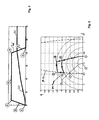
- FIG. 3 the stator flux path in a q-d stator flux coordinate system corresponding to the situation shown in FIG. 2 ,
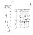
- FIG. 4 an other diagram similar to the diagram shown in FIG. 2 for a different situation, while the rotor is accelerated, and
- FIG. 5 the stator flux path corresponding to the situation shown in FIG. 4 .
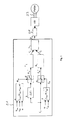
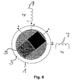
- FIG. 6 a schematic diagram showing a permanent magnet rotor rotating within the stator of a motor
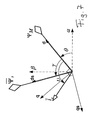
- FIG. 7 a diagram illustrating different notations of angles and coordinate axes.
- FIG. 6 shows schematically a permanent magnet synchronous motor 1 having a stator 3 and a rotor 5 .
- the magnetic flux of the stator 3 is produced, for example by two electromagnetic coils 7 , 9 which are perpendicularly oriented to each other.
- Coil 7 is oriented in the direction of the coordinate axis ⁇ of a non-rotating coordinate system.
- Coil 9 is oriented in the direction of the other coordinate axis ⁇ of the non-rotating coordinate system.
- the permanent magnet of rotor 5 produces a magnetic flux which is oriented in the direction d of a rotating coordinate system, the rotational speed of the rotating coordinate system being the rotation speed of the rotor 5 .
- the other (orthogonal to d) coordinate axis of the rotating coordinate system is denoted by “q”.
- FIG. 7 illustrates some notations and will be referred to in the following.
- FIG. 7 shows the situation of the rotating and of the non-rotating coordinate systems at a specific point in time which corresponds to the situation depicted in FIG. 6 .
- the rotor flux ⁇ M is always oriented in the direction of the coordinate axis d of the rotating coordinate system d-q.
- the angle between the coordinate axis ⁇ of the non-rotating coordinate system ⁇ - ⁇ and the coordinate axis d is denoted by ⁇ .
- the frequency of the stator voltage (and the same applies to the frequency of the stator current) is proportional to the first time derivative of the angle ⁇ . If the pole number of the motor is 2, the frequency of the stator voltage is equal to the first time derivative of the angle ⁇ .
- the angle between axis d and the magnetic stator flux ⁇ S is denoted by ⁇ .
- the angle between coordinate axis d and the stator current ⁇ S is denoted by ⁇ .
- the coordinate axis ds (“ds” in FIG. 7 ) is always in line with the stator flux vector ⁇ S .
- the coordinate axis qs (“qs” in FIG. 7 ) is orthogonal to ds which means that ds and qs define a coordinate system which is related to the stator flux.
- ⁇ S ⁇ M +L d i d +j ⁇ L q i q Eq. 2
- i d is the component of the stator current in the direction of coordinate axis d
- i q is the component of the stator current in the direction of coordinate axis q
- L d is the magnetic inductivity of the stator electromagnets in the direction of coordinate axis d
- L q is the magnetic inductivity of the stator electromagnets in the direction of axis q.
- the torque can be written as:
- I is the amount of the stator current ⁇ S .
- the corresponding value of the angle ⁇ is denoted by ⁇ 0 in the following.
- the results of the cosine of the angle ⁇ 0 , of the stator flux ⁇ 0 and of the torque T 0 are as follows:
- the optimum stator flux i.e. the stator flux which corresponds to the maximum torque to current ratio
- ⁇ 0 f ( T 0 , ⁇ M ,L d ,L q ) Eq. 8, wherein ⁇ represents “function”.
- This function which can be calculated using the equations given above, can be implemented in device b which is shown in FIG. 1 (which will be described below) and is a preferred embodiment of the predetermined function mentioned above in the general description of the invention.
- the flux vector can be calculated from a given current and flux magnitude, e.g. by using the following equations 9a and 9b:
- a limit value of the torque which corresponds to the limit value of the current i.e. the maximum current through the stator electromagnets
- this torque limit is a function of the amount of the stator flux, the maximum current, the rotor flux and of the complex inductivity in the d-q coordinate system of the magnetic inductivity of the stator electromagnets.
- T pull ( ⁇ ⁇ ⁇ ⁇ cos ⁇ ( ⁇ pull ) L q - ⁇ ⁇ ⁇ cos ⁇ ( ⁇ pull ) - ⁇ M L d ) ⁇ ⁇ ⁇ ⁇ ⁇ sin ⁇ ( ⁇ pull ) Eq . ⁇ 13
- the pull out torque is a function of the amount of the stator flux, of the amount of the rotor flux and of the magnetic inductivity of the stator electromagnets in the complex form written in the rotating coordinate system d-q.
- Device c according to FIG. 1 which is a preferred embodiment of the limiting device for calculating the reduced motor torque mentioned in the general description of the invention may be adapted to either output the pull out torque according to equation 13 or the torque which corresponds to the current limit according to equation 10, whichever torque is smaller.
- Device c can be omitted and it can be prevented by other means that the desired torque does not exceed the maximum allowed torque.
- other parameters and/or quantities which influence the motor control may be limited with the effect that the maximum allowed motor torque is never exceeded.
- a special limitating device is therefore not necessarily required.
- the torque is controlled by setting the load angle, i.e. controlling the load angle by the load angle controller according to the present invention.
- the load angle i.e. controlling the load angle by the load angle controller according to the present invention.
- the maximum electric voltage which can be used to drive the stator electromagnet currents limits the flux and the stator flux will, therefore, decrease.
- the torque is controlled using the load angle as a controlled variable.
- Device a of FIG. 1 which calculates a limit value of the stator flux, may be adapted to perform the two different limiting functions in these situations.
- Device a may output the minimum value of the maximum allowed stator flux or the maximum available voltage divided by the rotor speed and multiplied by a constant K, whichever value is smaller:
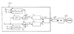
- FIG. 1 shows a control structure 21 for controlling a permanent magnet synchronous motor PMSM which may be a three-phase alternating current motor as indicated by three lines 23 .
- the motor PMSM is directly controlled using space vector modulation SVM, according to this particular example of the invention.
- the SVM is performed by device VSI using a standard direct to alternating current converter, i.e. an inverter, which may have three branches with, in each case, two semiconductor switches which are connected in series to each other.
- the commands for switching the semiconductor switches are produced in device VSI.
- the device VSI is controlled by the output of a modulator 25 which may function in a manner which is principally known in the art.
- the control structure 21 outputs a reference voltage V ref which is received by combining (in combining device h) output signals of a flux controller ⁇ and of a load angle controller g which are connected parallel to each other.
- the input voltages V d and V q are given in the rotating stator flux coordinates (ds-qs, see above FIG. 7 ).
- the flux controller ⁇ receives a reference value ⁇ * ref as an input value and operates on the basis of this input value.
- the reference value ⁇ * ref may be input to the flux controller ⁇ in the form of the difference between the reference value and the actual value of the flux.
- the flux controller may be, for example, a PI (proportional, integral) controller and may output a voltage V d which represents a reference voltage in the direction of the stator flux, i.e. in the direction of the coordinate axis ds (see FIG. 7 for the definition of ds) of the rotating coordinate system.
- the control method is performed using the coordinates of the system ds and qs (see above description of FIG. 7 ).
- the load angle controller g receives a signal T* ref as an input value and calculates on this basis a reference voltage V q as an output, wherein this reference voltage V q corresponds to a voltage controlling the component of the stator flux perpendicular to the coordinate axis qs (which is perpendicular to the direction of the stator flux). Therefore, the reference voltage V q controls the load angle between the stator flux and the rotor flux.
- the information about the torque reference value T* ref may be input to the load angle g in the form of the difference between the reference value T* ref and the actual value of the torque.
- the flux reference value ⁇ * ref which is input to the flux controller ⁇ , is output from a combination device d. If the stator flux is limited by limiting device a (the function of this device a was described above), the limited output value ⁇ lim is output by the combination device d as the reference value ⁇ * ref . In all other situations, the combination device d outputs the functional value of device b (the function of which was described above) as the reference value ⁇ * ref . The device b receives the desired torque T ref as an input value and calculates its output value on the basis of equation 8 and the preceding equations 5-7 for example.
- the desired torque T ref is also input to a further combination device e which either outputs the desired torque as the reference torque value T* ref or the output T lim of device c, the function of which was described above.
- Device c receives the actual value of the stator flux and the maximum value of the stator current.
- Device c may be operated according to equations 9-13, as described above.
- Device a receives the maximum allowed stator flux, the maximum available voltage to drive the stator currents and the actual speed of the rotor.
- the limiting device a comprises an input for receiving the maximum allowed stator flux, the maximum available voltage and the actual rotor speed.
- An output of the limiting device a is connected to the combination device d.
- Device b for calculating the functional value of the predetermined function mentioned above comprises an input for receiving the desired torque and comprises an output which is connected to an input of the combination device d.
- An output of the combination device d is connected to the flux controller ⁇ in order to transfer the flux reference value ⁇ * ref .
- An output of the flux controller is connected to the combination device h.
- the combination device e comprises an input for receiving the desired torque T ref and comprises an input for receiving a torque limit value T lim .
- This input is connected to an output of device c which has an input for receiving the actual stator flux magnitude and for receiving the maximum allowed current of the stator.
- An output of the combination device e for outputting the reference torque value T* ref is connected to an input of the load angle controller g.
- An output of the load angle controller g is connected to the combination device h.
- FIG. 2 shows the time axis as the horizontal axis of the diagram.
- the unit of the time axis may be one second, i.e. the time axis starts at zero and ends at 30 seconds.
- the vertical axis corresponds to the desired torque value T ref and to the rotor speed ⁇ .
- FIG. 3 shows the stator flux in the rotating d-q coordinate system.
- the stator flux develops as shown on solid line and as indicated by six arrows. Certain points in time and the corresponding stator flux are denoted by letters A-E in FIG. 3 .
- Corresponding times and values of the desired torque T ref are also indicated in FIG. 2 .
- the course of the desired torque T ref in FIG. 2 has a trapezoidal form.
- the acceleration process starts at stand still, for example when the rotor of the motor is not rotating or when the motor does not produce a torque. This is indicated by letter A.
- the desired torque T ref is linearly increased.
- the stator flux follows a nearly linear, but slightly bent line in the diagram of FIG. 3 from point A to B.
- the q-component of the stator flux is increased from zero to a value of about 1.2. This means that the load angle is continuously increased according to the continuous increase of the desired torque T ref .
- the characteristic feature of path A-B is that the location of this path in the stator flux diagram shown in FIG.
- path A-B in FIG. 3 is controlled by device b which outputs its functional value and this functional value is output by combination device d as the reference value ⁇ * ref to the flux controller.
- the load angle controller receives as input value the desired torque T ref .
- the limiting devices a and c do not influence the output of the control structure during this phase of operation.
- the maximum allowed stator flux corresponds to the dashed circular line which is denoted by
- ⁇ max .
- points B and C may be identical, i.e. path A-B in FIG. 3 would be followed directly by path C-D. This happens for example if the magnitude of the electric currents through the electromagnets of the stator has reached a predetermined maximum value when or before the maximum allowed state of flux is reached.
- the increased torque can not be achieved by further increasing the reference value ⁇ * ref which is the input value of the flux controller ⁇ in FIG. 1 . Rather, the limiting device a limits this reference value to the maximum possible value so that the maximum allowed stator flux ⁇ max is not exceeded.
- the load angle controller g which receives the desired torque as its reference value T* ref , outputs a control signal in order to increase the load angle.
- the path B-C in FIG. 3 follows the circular line of the maximum allowed stator flux, thereby increasing the load angle, which is denoted in FIG. 7 ⁇ . Therefore, in FIG.
- the operation made by following path B-C is achieved by rotating the pointer denoted by ⁇ S in anti-clockwise direction so that the load angle ⁇ is increased.
- the reference value ⁇ * ref which is the input value of the flux controller ⁇ is, as mentioned, provided by the limit value ⁇ lim .
- the input value T* ref which is the input value of the load angle controller g is equal to the desired torque value T ref . Since the flux controller ⁇ can not contribute to the desired increase of the motor torque, the load angle controller g will deliver the required output signal.
- the load angle controller g is also a PI-controller. This means that the limiting device a passivates the function of the flux controller ⁇ . On the other hand, the limiting device c has no influence on the output of the control structure 21 in phase which corresponds to path B-C.
- the desired torque T ref reaches its maximum value and is kept constant in the following phase of operation. Therefore, the maximum allowed current through the electromagnets of the stator is reached.
- the corresponding line of the stator flux in FIG. 3 which corresponds to constant stator current is indicated
- 2 and is a section of an ellipse.
- the stator flux is not decreasing, but is constant. Rather, since the torque is not to be increased, the stator flux can remain at point C, but the torque can accelerate the rotor at constant flux magnitude and at constant load angle.
- the combination device e outputs the reduced torque value T ref instead of the limited torque value T lim and the load angle controller d reacts by decreasing the load angle, while the stator flux magnitude is kept (by function a) at the limit (either the maximum allowed flux or the maximum possible flux whichever is smaller) by the flux controller ⁇ .
- the phases from C-D and from D-E can be defined by the concept that the stator flux is kept at the maximum possible flux (which depends on the available voltage and on the rotor speed), i.e. the flux is as high as possible during these phases.
- the stator flux reaches the path which is characterized by the condition that the torque can be produced by the minimum possible current through the stator electromagnets.
- the control structure 21 starts operating in the same manner as described above for path A-B, wherein the limiting devices a and c are not influencing the output of the control structure 21 . Rather, device b influences flux controller ⁇ so that flux controller ⁇ reduces the stator flux on path E-A.
- FIGS. 4 and 5 illustrate a similar acceleration process.
- the stator flux reaches the line O-P which indicates the maximum allowed load angle of the motor.
- the torque demand i.e. the desired torque
- the stator flux follows a line from point G-H.
- the stator flux is kept at the maximum possible flux (depending on speed and voltage).
- the function of the control structure 21 on path G-H is the same as for path D-E in FIG. 3 , but on a smaller level of the stator flux magnitude.
Applications Claiming Priority (4)
| Application Number | Priority Date | Filing Date | Title |
|---|---|---|---|
| EP08014129.4 | 2008-08-07 | ||
| EP20080014129 EP2151918A1 (en) | 2008-08-07 | 2008-08-07 | Operating a synchronous motor having a permanent magnet rotor |
| EP08014129 | 2008-08-07 | ||
| PCT/EP2009/005894 WO2010015424A1 (en) | 2008-08-07 | 2009-08-07 | Operating a synchronous motor having a permanent magnet rotor |
Publications (2)
| Publication Number | Publication Date |
|---|---|
| US20110162554A1 US20110162554A1 (en) | 2011-07-07 |
| US8410742B2 true US8410742B2 (en) | 2013-04-02 |
Family
ID=39992133
Family Applications (1)
| Application Number | Title | Priority Date | Filing Date |
|---|---|---|---|
| US13/057,819 Active 2030-02-26 US8410742B2 (en) | 2008-08-07 | 2009-08-07 | Operating a synchronous motor having a permanent magnet rotor |
Country Status (6)
| Country | Link |
|---|---|
| US (1) | US8410742B2 (zh) |
| EP (2) | EP2151918A1 (zh) |
| CN (1) | CN102144356B (zh) |
| AT (1) | ATE545982T1 (zh) |
| ES (1) | ES2380617T3 (zh) |
| WO (1) | WO2010015424A1 (zh) |
Cited By (1)
| Publication number | Priority date | Publication date | Assignee | Title |
|---|---|---|---|---|
| US20130207589A1 (en) * | 2010-07-28 | 2013-08-15 | Moritz Margner | Method and Device for Regulating Separately Excited Synchronous Machines |
Families Citing this family (14)
| Publication number | Priority date | Publication date | Assignee | Title |
|---|---|---|---|---|
| ES2552058T3 (es) * | 2006-10-19 | 2015-11-25 | Siemens Aktiengesellschaft | Instalación de energía eólica y método para controlar la potencia de salida de una instalación de energía eólica |
| PL2503676T3 (pl) * | 2011-03-25 | 2019-02-28 | Bombardier Transportation Gmbh | Sposób instalacji resolwera |
| US9000694B2 (en) | 2012-03-23 | 2015-04-07 | Fanuc Corporation | Synchronous motor control apparatus |
| JP5462906B2 (ja) * | 2012-04-16 | 2014-04-02 | 山洋電気株式会社 | モータ制御装置 |
| CN103036499B (zh) * | 2012-11-29 | 2015-03-04 | 浙江大学 | 一种永磁电动机转子位置的检测方法 |
| JP5620527B2 (ja) * | 2013-02-05 | 2014-11-05 | 山洋電気株式会社 | モータ制御装置 |
| CN103731082B (zh) * | 2014-01-03 | 2016-05-18 | 东南大学 | 一种基于直接转矩控制的永磁同步电机定子磁链估计方法 |
| CN106416050B (zh) * | 2014-05-21 | 2019-10-22 | 大陆-特韦斯贸易合伙股份公司及两合公司 | 用于控制制动系统的方法 |
| CN109565251B (zh) * | 2016-07-01 | 2022-06-24 | Abb瑞士股份有限公司 | 启动感应机器 |
| CN107453664B (zh) * | 2017-08-04 | 2019-09-20 | 浙江大学 | 一种基于模型预测的三相四开关逆变器永磁同步电机系统磁链控制方法 |
| CN111162715B (zh) * | 2018-11-08 | 2023-09-15 | 中车永济电机有限公司 | 一种电力机车用兆瓦级直驱永磁电传动系统 |
| CN109902445B (zh) * | 2019-04-01 | 2023-02-28 | 北斗航天汽车(北京)有限公司 | 一种ipm永磁电机的峰值转矩模拟测试方法及模拟测试系统 |
| US11239780B1 (en) * | 2020-09-24 | 2022-02-01 | Rockwell Automation Technologies, Inc. | Iterative flux identification |
| IL302737A (en) * | 2020-11-17 | 2023-07-01 | Economotor Innovation Ltd | Method and device for synchronous motor control |
Citations (12)
| Publication number | Priority date | Publication date | Assignee | Title |
|---|---|---|---|---|
| JPH1014273A (ja) | 1996-06-24 | 1998-01-16 | Railway Technical Res Inst | 車両駆動用永久磁石同期電動機の制御装置 |
| JPH11299297A (ja) | 1998-04-15 | 1999-10-29 | Fuji Electric Co Ltd | 永久磁石同期電動機の制御装置 |
| US6002234A (en) * | 1995-06-05 | 1999-12-14 | Kollmorgen Corporation | System and method for controlling brushless permanent magnet motors |
| US20040036434A1 (en) * | 2002-06-03 | 2004-02-26 | Ballard Power Systems Corporation | Method and apparatus for motor control |
| US20040257028A1 (en) | 2003-06-23 | 2004-12-23 | Schulz Steven E. | Position sensorless control algorithm for AC machine |
| US20060055363A1 (en) | 2004-09-13 | 2006-03-16 | Patel Nitinkumar R | Field weakening motor control system and method |
| US20080030155A1 (en) * | 2003-08-11 | 2008-02-07 | Patel Nitinkumar R | Gearless wheel motor drive system |
| US20080136380A1 (en) * | 2003-08-06 | 2008-06-12 | Siemens Aktiengesellschaft | Method for Controlled Application of a Stator Current Set Point Value and of a Torque Set Point Value for a Converter-Fed Rotating-Field Machine |
| US20080303475A1 (en) * | 2007-06-07 | 2008-12-11 | Patel Nitinkumar R | Method and system for torque control in permanent magnet machines |
| US7586286B2 (en) * | 2006-11-17 | 2009-09-08 | Continental Automotive Systems Us, Inc. | Method and apparatus for motor control |
| US20100060223A1 (en) * | 2007-03-26 | 2010-03-11 | Kabushiki Kaisha Toshiba | Permanent magnet rotating electrical machine and permanent magnet motor drive system |
| US20100327585A1 (en) * | 2009-06-30 | 2010-12-30 | Vestas Wind Systems A/S | Control System for an Electrical Generator and Method for Controlling an Electrical Generator |
Family Cites Families (1)
| Publication number | Priority date | Publication date | Assignee | Title |
|---|---|---|---|---|
| JP5167631B2 (ja) * | 2006-11-30 | 2013-03-21 | 株式会社デンソー | モータの制御方法及びそれを利用するモータ制御装置 |
-
2008
- 2008-08-07 EP EP20080014129 patent/EP2151918A1/en not_active Withdrawn
-
2009
- 2009-08-07 US US13/057,819 patent/US8410742B2/en active Active
- 2009-08-07 ES ES09777875T patent/ES2380617T3/es active Active
- 2009-08-07 AT AT09777875T patent/ATE545982T1/de active
- 2009-08-07 EP EP20090777875 patent/EP2319172B1/en active Active
- 2009-08-07 CN CN2009801347327A patent/CN102144356B/zh active Active
- 2009-08-07 WO PCT/EP2009/005894 patent/WO2010015424A1/en active Application Filing
Patent Citations (13)
| Publication number | Priority date | Publication date | Assignee | Title |
|---|---|---|---|---|
| US6002234A (en) * | 1995-06-05 | 1999-12-14 | Kollmorgen Corporation | System and method for controlling brushless permanent magnet motors |
| JPH1014273A (ja) | 1996-06-24 | 1998-01-16 | Railway Technical Res Inst | 車両駆動用永久磁石同期電動機の制御装置 |
| JPH11299297A (ja) | 1998-04-15 | 1999-10-29 | Fuji Electric Co Ltd | 永久磁石同期電動機の制御装置 |
| US20040036434A1 (en) * | 2002-06-03 | 2004-02-26 | Ballard Power Systems Corporation | Method and apparatus for motor control |
| US20040257028A1 (en) | 2003-06-23 | 2004-12-23 | Schulz Steven E. | Position sensorless control algorithm for AC machine |
| US20080136380A1 (en) * | 2003-08-06 | 2008-06-12 | Siemens Aktiengesellschaft | Method for Controlled Application of a Stator Current Set Point Value and of a Torque Set Point Value for a Converter-Fed Rotating-Field Machine |
| US7746039B2 (en) * | 2003-08-06 | 2010-06-29 | Siemens Aktiengesellschaft | Method for controlled application of a stator current set point value and of a torque set point value for a converter-fed rotating-field machine |
| US20080030155A1 (en) * | 2003-08-11 | 2008-02-07 | Patel Nitinkumar R | Gearless wheel motor drive system |
| US20060055363A1 (en) | 2004-09-13 | 2006-03-16 | Patel Nitinkumar R | Field weakening motor control system and method |
| US7586286B2 (en) * | 2006-11-17 | 2009-09-08 | Continental Automotive Systems Us, Inc. | Method and apparatus for motor control |
| US20100060223A1 (en) * | 2007-03-26 | 2010-03-11 | Kabushiki Kaisha Toshiba | Permanent magnet rotating electrical machine and permanent magnet motor drive system |
| US20080303475A1 (en) * | 2007-06-07 | 2008-12-11 | Patel Nitinkumar R | Method and system for torque control in permanent magnet machines |
| US20100327585A1 (en) * | 2009-06-30 | 2010-12-30 | Vestas Wind Systems A/S | Control System for an Electrical Generator and Method for Controlling an Electrical Generator |
Non-Patent Citations (3)
| Title |
|---|
| Ghassemi et al., "A very fast direct torque control for interior permanent magnet synchronous motors start up", Energy Conversion and Management, 2005, pp. 715-726, 46. |
| Luukko et al., "Limitation of the Load Angle in a Direct-Torque-Controlled Synchronous Machine Drive", IEEE Transactions on Industrial Electronics, Aug. 2004, pp. 793-798, vol. 51, No. 4. |
| Swierczynski et al., "DSP Based Direct Torque Control of Permanent Magnet Synchronous Motor (PMSM) Using Space Vector Modulation (DTC-SVM)", IEEE, 2002, pp. 723-727. |
Cited By (2)
| Publication number | Priority date | Publication date | Assignee | Title |
|---|---|---|---|---|
| US20130207589A1 (en) * | 2010-07-28 | 2013-08-15 | Moritz Margner | Method and Device for Regulating Separately Excited Synchronous Machines |
| US9048773B2 (en) * | 2010-07-28 | 2015-06-02 | Continental Automotive Gmbh | Method and device for regulating separately excited synchronous machines |
Also Published As
| Publication number | Publication date |
|---|---|
| ES2380617T3 (es) | 2012-05-16 |
| CN102144356A (zh) | 2011-08-03 |
| EP2319172A1 (en) | 2011-05-11 |
| EP2151918A1 (en) | 2010-02-10 |
| EP2319172B1 (en) | 2012-02-15 |
| ATE545982T1 (de) | 2012-03-15 |
| US20110162554A1 (en) | 2011-07-07 |
| CN102144356B (zh) | 2013-11-06 |
| WO2010015424A1 (en) | 2010-02-11 |
Similar Documents
| Publication | Publication Date | Title |
|---|---|---|
| US8410742B2 (en) | Operating a synchronous motor having a permanent magnet rotor | |
| US7548443B2 (en) | Three-phase PWM-signal generating apparatus | |
| KR101157732B1 (ko) | 전동기의 제어 장치 | |
| US8174222B2 (en) | Methods, systems and apparatus for dynamically controlling an electric motor that drives an oil pump | |
| US7145310B2 (en) | Method and system for controlling permanent magnet synchronous motor | |
| US6326762B1 (en) | Method of braking a vector controlled induction machine, control device for carrying out the method and storage medium | |
| JP5281339B2 (ja) | 同期電動機の駆動システム、及びこれに用いる制御装置 | |
| EP2068438A1 (en) | Permanent magnet synchronization motor vector control device | |
| EP3509210B1 (en) | Inverter control device and electric motor driving system | |
| US20140028228A1 (en) | Control systems and methods for angle estimation of permanent magnet motors | |
| US6438321B1 (en) | Control of high speed DC motor vertical voltage vector component | |
| JPH11299297A (ja) | 永久磁石同期電動機の制御装置 | |
| EP3128668A1 (en) | Electric apparatus drive device | |
| JPH08275599A (ja) | 永久磁石同期電動機の制御方法 | |
| US20230219426A1 (en) | Pulse modulated control with field weakening for improved machine efficiency | |
| JP2012120320A (ja) | 回転センサレス制御装置 | |
| JP3515047B2 (ja) | Dcブラシレスモータ装置 | |
| US9000701B2 (en) | Methods, systems and apparatus for generating voltage commands used to control operation of a permanent magnet machine | |
| EP2571157B1 (en) | Method and device for controlling power to an electric machine | |
| CN111585489A (zh) | 一种基于无永磁磁链观测器的定子永磁型记忆电机弱磁控制方法 | |
| WO2023195172A1 (ja) | モータ制御装置、モータ制御方法 | |
| JP2006042444A (ja) | モータ制御装置 | |
| AU2819999A (en) | Motor conroller |
Legal Events
| Date | Code | Title | Description |
|---|---|---|---|
| AS | Assignment |
Owner name: BOMBARDIER TRANSPORTATION GMBH, GERMANY Free format text: ASSIGNMENT OF ASSIGNORS INTEREST;ASSIGNOR:GALIC, JOHANN;REEL/FRAME:025917/0219 Effective date: 20110218 |
|
| FEPP | Fee payment procedure |
Free format text: PAYOR NUMBER ASSIGNED (ORIGINAL EVENT CODE: ASPN); ENTITY STATUS OF PATENT OWNER: LARGE ENTITY |
|
| STCF | Information on status: patent grant |
Free format text: PATENTED CASE |
|
| CC | Certificate of correction | ||
| CC | Certificate of correction | ||
| FPAY | Fee payment |
Year of fee payment: 4 |
|
| MAFP | Maintenance fee payment |
Free format text: PAYMENT OF MAINTENANCE FEE, 8TH YEAR, LARGE ENTITY (ORIGINAL EVENT CODE: M1552); ENTITY STATUS OF PATENT OWNER: LARGE ENTITY Year of fee payment: 8 |