US8402940B2 - Engine having fuel injection induced combustion chamber mixing - Google Patents
Engine having fuel injection induced combustion chamber mixing Download PDFInfo
- Publication number
- US8402940B2 US8402940B2 US12/752,235 US75223510A US8402940B2 US 8402940 B2 US8402940 B2 US 8402940B2 US 75223510 A US75223510 A US 75223510A US 8402940 B2 US8402940 B2 US 8402940B2
- Authority
- US
- United States
- Prior art keywords
- combustion chamber
- fuel
- piston
- circumference
- circumferential
- Prior art date
- Legal status (The legal status is an assumption and is not a legal conclusion. Google has not performed a legal analysis and makes no representation as to the accuracy of the status listed.)
- Expired - Fee Related, expires
Links
Images


Classifications
-
- F—MECHANICAL ENGINEERING; LIGHTING; HEATING; WEAPONS; BLASTING
- F02—COMBUSTION ENGINES; HOT-GAS OR COMBUSTION-PRODUCT ENGINE PLANTS
- F02B—INTERNAL-COMBUSTION PISTON ENGINES; COMBUSTION ENGINES IN GENERAL
- F02B23/00—Other engines characterised by special shape or construction of combustion chambers to improve operation
- F02B23/02—Other engines characterised by special shape or construction of combustion chambers to improve operation with compression ignition
- F02B23/06—Other engines characterised by special shape or construction of combustion chambers to improve operation with compression ignition the combustion space being arranged in working piston
- F02B23/0645—Details related to the fuel injector or the fuel spray
- F02B23/066—Details related to the fuel injector or the fuel spray the injector being located substantially off-set from the cylinder centre axis
-
- F—MECHANICAL ENGINEERING; LIGHTING; HEATING; WEAPONS; BLASTING
- F02—COMBUSTION ENGINES; HOT-GAS OR COMBUSTION-PRODUCT ENGINE PLANTS
- F02B—INTERNAL-COMBUSTION PISTON ENGINES; COMBUSTION ENGINES IN GENERAL
- F02B23/00—Other engines characterised by special shape or construction of combustion chambers to improve operation
- F02B23/02—Other engines characterised by special shape or construction of combustion chambers to improve operation with compression ignition
- F02B23/06—Other engines characterised by special shape or construction of combustion chambers to improve operation with compression ignition the combustion space being arranged in working piston
- F02B23/0618—Other engines characterised by special shape or construction of combustion chambers to improve operation with compression ignition the combustion space being arranged in working piston having in-cylinder means to influence the charge motion
- F02B23/0624—Swirl flow
-
- F—MECHANICAL ENGINEERING; LIGHTING; HEATING; WEAPONS; BLASTING
- F02—COMBUSTION ENGINES; HOT-GAS OR COMBUSTION-PRODUCT ENGINE PLANTS
- F02B—INTERNAL-COMBUSTION PISTON ENGINES; COMBUSTION ENGINES IN GENERAL
- F02B23/00—Other engines characterised by special shape or construction of combustion chambers to improve operation
- F02B23/08—Other engines characterised by special shape or construction of combustion chambers to improve operation with positive ignition
- F02B23/10—Other engines characterised by special shape or construction of combustion chambers to improve operation with positive ignition with separate admission of air and fuel into cylinder
- F02B23/104—Other engines characterised by special shape or construction of combustion chambers to improve operation with positive ignition with separate admission of air and fuel into cylinder the injector being placed on a side position of the cylinder
-
- F—MECHANICAL ENGINEERING; LIGHTING; HEATING; WEAPONS; BLASTING
- F02—COMBUSTION ENGINES; HOT-GAS OR COMBUSTION-PRODUCT ENGINE PLANTS
- F02B—INTERNAL-COMBUSTION PISTON ENGINES; COMBUSTION ENGINES IN GENERAL
- F02B23/00—Other engines characterised by special shape or construction of combustion chambers to improve operation
- F02B23/08—Other engines characterised by special shape or construction of combustion chambers to improve operation with positive ignition
- F02B23/10—Other engines characterised by special shape or construction of combustion chambers to improve operation with positive ignition with separate admission of air and fuel into cylinder
- F02B2023/103—Other engines characterised by special shape or construction of combustion chambers to improve operation with positive ignition with separate admission of air and fuel into cylinder the injector having a multi-hole nozzle for generating multiple sprays
-
- F—MECHANICAL ENGINEERING; LIGHTING; HEATING; WEAPONS; BLASTING
- F02—COMBUSTION ENGINES; HOT-GAS OR COMBUSTION-PRODUCT ENGINE PLANTS
- F02B—INTERNAL-COMBUSTION PISTON ENGINES; COMBUSTION ENGINES IN GENERAL
- F02B23/00—Other engines characterised by special shape or construction of combustion chambers to improve operation
- F02B23/08—Other engines characterised by special shape or construction of combustion chambers to improve operation with positive ignition
- F02B23/10—Other engines characterised by special shape or construction of combustion chambers to improve operation with positive ignition with separate admission of air and fuel into cylinder
- F02B2023/108—Swirl flow, i.e. the axis of rotation of the main charge flow motion is vertical
-
- F—MECHANICAL ENGINEERING; LIGHTING; HEATING; WEAPONS; BLASTING
- F02—COMBUSTION ENGINES; HOT-GAS OR COMBUSTION-PRODUCT ENGINE PLANTS
- F02B—INTERNAL-COMBUSTION PISTON ENGINES; COMBUSTION ENGINES IN GENERAL
- F02B2275/00—Other engines, components or details, not provided for in other groups of this subclass
- F02B2275/14—Direct injection into combustion chamber
-
- F—MECHANICAL ENGINEERING; LIGHTING; HEATING; WEAPONS; BLASTING
- F02—COMBUSTION ENGINES; HOT-GAS OR COMBUSTION-PRODUCT ENGINE PLANTS
- F02B—INTERNAL-COMBUSTION PISTON ENGINES; COMBUSTION ENGINES IN GENERAL
- F02B23/00—Other engines characterised by special shape or construction of combustion chambers to improve operation
- F02B23/02—Other engines characterised by special shape or construction of combustion chambers to improve operation with compression ignition
- F02B23/06—Other engines characterised by special shape or construction of combustion chambers to improve operation with compression ignition the combustion space being arranged in working piston
- F02B23/0645—Details related to the fuel injector or the fuel spray
- F02B23/0669—Details related to the fuel injector or the fuel spray having multiple fuel spray jets per injector nozzle
-
- F—MECHANICAL ENGINEERING; LIGHTING; HEATING; WEAPONS; BLASTING
- F02—COMBUSTION ENGINES; HOT-GAS OR COMBUSTION-PRODUCT ENGINE PLANTS
- F02B—INTERNAL-COMBUSTION PISTON ENGINES; COMBUSTION ENGINES IN GENERAL
- F02B25/00—Engines characterised by using fresh charge for scavenging cylinders
- F02B25/02—Engines characterised by using fresh charge for scavenging cylinders using unidirectional scavenging
- F02B25/08—Engines with oppositely-moving reciprocating working pistons
-
- F—MECHANICAL ENGINEERING; LIGHTING; HEATING; WEAPONS; BLASTING
- F02—COMBUSTION ENGINES; HOT-GAS OR COMBUSTION-PRODUCT ENGINE PLANTS
- F02M—SUPPLYING COMBUSTION ENGINES IN GENERAL WITH COMBUSTIBLE MIXTURES OR CONSTITUENTS THEREOF
- F02M61/00—Fuel-injectors not provided for in groups F02M39/00 - F02M57/00 or F02M67/00
- F02M61/04—Fuel-injectors not provided for in groups F02M39/00 - F02M57/00 or F02M67/00 having valves, e.g. having a plurality of valves in series
- F02M61/08—Fuel-injectors not provided for in groups F02M39/00 - F02M57/00 or F02M67/00 having valves, e.g. having a plurality of valves in series the valves opening in direction of fuel flow
-
- F—MECHANICAL ENGINEERING; LIGHTING; HEATING; WEAPONS; BLASTING
- F02—COMBUSTION ENGINES; HOT-GAS OR COMBUSTION-PRODUCT ENGINE PLANTS
- F02M—SUPPLYING COMBUSTION ENGINES IN GENERAL WITH COMBUSTIBLE MIXTURES OR CONSTITUENTS THEREOF
- F02M69/00—Low-pressure fuel-injection apparatus ; Apparatus with both continuous and intermittent injection; Apparatus injecting different types of fuel
- F02M69/04—Injectors peculiar thereto
- F02M69/042—Positioning of injectors with respect to engine, e.g. in the air intake conduit
- F02M69/045—Positioning of injectors with respect to engine, e.g. in the air intake conduit for injecting into the combustion chamber
-
- Y—GENERAL TAGGING OF NEW TECHNOLOGICAL DEVELOPMENTS; GENERAL TAGGING OF CROSS-SECTIONAL TECHNOLOGIES SPANNING OVER SEVERAL SECTIONS OF THE IPC; TECHNICAL SUBJECTS COVERED BY FORMER USPC CROSS-REFERENCE ART COLLECTIONS [XRACs] AND DIGESTS
- Y02—TECHNOLOGIES OR APPLICATIONS FOR MITIGATION OR ADAPTATION AGAINST CLIMATE CHANGE
- Y02T—CLIMATE CHANGE MITIGATION TECHNOLOGIES RELATED TO TRANSPORTATION
- Y02T10/00—Road transport of goods or passengers
- Y02T10/10—Internal combustion engine [ICE] based vehicles
- Y02T10/12—Improving ICE efficiencies
Definitions
- the present disclosure relates to internal combustion engines including direct injection fuel systems.
- Engine assemblies may include direct engine fuel systems providing a fuel supply directly to a combustion chamber of the engine.
- the direct injection fuel systems may include a centrally located fuel injector.
- the fuel injector may provide multiple radial fuel jets directed toward the combustion chamber walls. The orientation of the fuel injector and the resulting fuel flow may result in the fuel impacting the combustion chamber walls and therefore limiting mixing within the combustion chamber.
- An engine assembly may include an engine structure, a piston, and a direct injection fuel system.
- the engine structure may define a cylinder bore and the piston may be disposed within the cylinder bore for reciprocal displacement between a top dead center position and a bottom dead center position.
- the direct injection fuel system may include a fuel injector that provides a fuel spray to a combustion chamber defined by the piston and the engine structure.
- the fuel flow may extend generally tangential to a circumference of the combustion chamber and may define a centerline extending in a direction radially across the combustion chamber.
- a method may include providing a direct injection fuel injector in communication with a combustion chamber of an internal combustion engine defined by an engine structure and a piston disposed in a cylinder bore defined by the engine structure. The method may further include injecting an air entraining fuel spray from the fuel injector directly into the combustion chamber generally tangential to a circumferential sidewall of the combustion chamber. A rotational flow of the fuel spray and the remaining air within the combustion chamber may be generated by the tangential fuel injection.
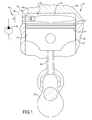
- FIG. 1 is a schematic section view of an engine assembly according to the present disclosure
- FIG. 2 is an additional schematic section view of the engine assembly of FIG. 1 ;
- FIG. 3 is a schematic section view of an alternate engine assembly according to the present disclosure
- FIG. 4 is an additional schematic section view of the engine assembly of FIG. 3 ;
- FIG. 5 is a schematic section view of an alternate engine assembly according to the present disclosure.
- FIG. 6 is an additional schematic section view of the engine assembly of FIG. 5 ;
- FIG. 7 is a schematic illustration of a first fuel injector nozzle according to the present disclosure.
- FIG. 8 is a schematic illustration of a second fuel injector nozzle according to the present disclosure.
- FIG. 9 is a schematic illustration of a third fuel injector nozzle according to the present disclosure.
- FIG. 10 is a graphical illustration of an alternate injection arrangement according to the present disclosure.
- FIG. 11 is a schematic illustration of an engine assembly including the injection arrangement of FIG. 10 ;
- FIG. 12 is a schematic illustration of an alternate engine assembly according to the present disclosure.
- Example embodiments are provided so that this disclosure will be thorough, and will fully convey the scope to those who are skilled in the art. Numerous specific details are set forth such as examples of specific components, devices, and methods, to provide a thorough understanding of embodiments of the present disclosure. It will be apparent to those skilled in the art that specific details need not be employed, that example embodiments may be embodied in many different forms and that neither should be construed to limit the scope of the disclosure. In some example embodiments, well-known processes, well-known device structures, and well-known technologies are not described in detail.
- first, second, third, etc. may be used herein to describe various elements, components, regions, layers and/or sections, these elements, components, regions, layers and/or sections should not be limited by these terms. These terms may be only used to distinguish one element, component, region, layer or section from another region, layer or section. Terms such as “first,” “second,” and other numerical terms when used herein do not imply a sequence or order unless clearly indicated by the context. Thus, a first element, component, region, layer or section discussed below could be termed a second element, component, region, layer or section without departing from the teachings of the example embodiments.
- an engine assembly 10 may include an engine structure 12 , a fuel system 14 and a piston 16 coupled to a crankshaft 18 by a connecting rod 20 .
- the engine structure 12 may include an engine block 22 defining a cylinder bore 24 and a cylinder head 26 defining intake and exhaust ports 28 , 30 .
- the piston 16 may be disposed within the cylinder bore 24 and may be reciprocally displaceable between a top dead center (TDC) position and a bottom dead center (BDC) position to drive rotation of the crankshaft 18 .
- TDC top dead center
- BDC bottom dead center
- the present disclosure applies equally to engines including any number of piston/cylinder arrangements, including opposed piston configurations ( FIG. 12 ), as well as overhead cam and cam in block arrangements.
- the present disclosure also applies equally to diesel and direct injection gasoline engines.
- the piston 16 and the engine structure 12 cooperate to define a combustion chamber 32 .
- the pistons 16 may have seal rings 41 engaged with an outer circumference thereof and with the engine structure 12 to isolate the combustion chamber 32 from the engine crankcase.
- the combustion chamber 32 may include a round cross-section defining a circumference of the combustion chamber 32 .
- the fuel system 14 may include a fuel pump 34 providing a pressurized fuel supply to a fuel injector 36 .
- the fuel provided to the fuel injector 36 may be at an operating pressure of at least one hundred and twenty mega Pascal (120 MPa), and more specifically greater than two hundred mega Pascal (200 MPa) during high load operation.
- the fuel system 14 may be operated at reduced pressures at low and part load operation of the engine.
- the fuel injector 36 is in direct communication with the combustion chamber 32 forming a direct injection arrangement.
- the fuel injector 36 may be incorporated into a fuel rail (not shown) having a plurality of fuel injectors.
- the fuel injector 36 may extend through a sidewall 40 of the combustion chamber 32 and provide a fuel spray (F 1 ) extending radially into the combustion chamber 32 .
- the fuel spray (F 1 ) may be in the form of a finely atomized spray.
- the fuel spray (F 1 ) may be located axially above the seal rings 41 of the piston 16 when the piston 16 is in the TDC position.
- the fuel spray (F 1 ) may extend generally tangential to the sidewall (circumference) 40 of the combustion chamber 32 . More specifically, the fuel spray (F 1 ) may define a fuel spray pattern including centerline (C 1 ) between inner and outer radial peripheries (P 1 i , P 1 o ).
- the centerline (C 1 ) may extend in a direction across the combustion chamber 32 from a circumferential starting point 42 to a first circumferential ending point 44 where the centerline (C 1 ) intersects the cylinder bore 24 .
- the first circumferential ending point 44 may be circumferentially spaced (rotationally offset) from the circumferential starting point 42 by an angle ( ⁇ 1 ) of less than or equal to one hundred and thirty-five degrees.
- the outer radial periphery (P 1 o ) may extend in a direction intersecting the cylinder bore 24 at a second circumferential ending point 46 circumferentially spaced (rotationally offset) from the circumferential starting point 42 by an angle ( ⁇ 2 ) of less than or equal to ninety degrees.
- the fuel spray (F 1 ) may define an angular span ( ⁇ 3 ) of less than or equal to thirty degrees.
- the fuel spray (F 1 ) may include multiple plumes.
- the multiple plumes may be generated by a nozzle 48 of the fuel injector 36 defining a plurality of apertures 50 selectively opened by a pintle valve 51 as illustrated in FIG. 7 .
- the fuel spray (F 1 ) may alternatively include a single plume.
- the single plume may be generated by a nozzle 52 of the fuel injector 36 defining a single opening 54 and a poppet valve 56 as illustrated in FIG. 8 .
- a nozzle 58 defining a single opening 60 may be used with a pintle valve 62 to form a single annular plume.
- the high operating pressure of the pressurized fuel supply and the orientation of the fuel spray (F 1 ) relative to the combustion chamber 32 may create a rotational swirl spray within the combustion chamber 32 and provide mixing.
- the gas within the combustion chamber herein described as “air” may include recirculated exhaust products from previous combustion cycles.
- the fuel spray (F 1 ) may travel in a rotational direction (R 1 ) about a rotational axis (A 1 ) generally parallel to the direction of reciprocation of the piston 16 .
- the momentum of the fuel spray (F 1 ) within the combustion chamber 32 may provide mixing of the air charge and fuel within the combustion chamber 32 and generate rotational flow of the fuel spray (F 1 ) and air charge mixture (fuel-air charge).
- the momentum of the fuel spray (F 1 ) may be sufficient to provide for a complete rotation of the fuel-air charge around the combustion chamber 32 during an injection event for a corresponding combustion event (in-cylinder combustion corresponding to a power stroke).
- the fuel delivered to the combustion chamber 32 at the start of the injection event (initial injection) may travel at least three hundred and sixty degrees about the rotational axis (A 1 ), returning to the injection location by the end of the injection event (injection termination).
- the time from the start of the injection event to the end of the injection event may define a fuel injection period.
- the injection of the fuel may be done in multiple events (F 1 A , F 1 B , F 1 c , F 1 D , F 1 E ) over an extended period of time to distribute the fuel more uniformly in the combustion chamber 32 .
- FIG. 10 graphically illustrates the multiple injections.
- the x-axis in FIG. 10 is time (t) and the y-axis is injector opening, where “0” is closed and “1” is open.
- the fuel spray (F 1 ) may contain a linear momentum (M) which is approximately directly proportional to the injection pressure level and the duration of the injection.
- M linear momentum
- the combustion chamber fuel-air charge at the end of the injection event has a final rotational velocity ( ⁇ ) approximated by the product of spray momentum (M) and its tangential distance (R) to the center of the combustion chamber 32 divided by the moment of inertia (I) of the combustion chamber gas.
- the final rotational velocity ( ⁇ ) would be further increased by any initial rotating velocity, or swirl, ( ⁇ o ) of the fuel-air charge that existed in the combustion chamber prior to the injection event.
- FIGS. 3 and 4 An alternate engine assembly 110 is illustrated in FIGS. 3 and 4 .
- the engine assembly 110 may be generally similar to the engine assembly 10 . Therefore, for simplicity, the engine assembly 110 will not be described in detail with the understanding that the description of the engine assembly 10 applies equally with the exceptions noted below.
- the piston 116 in the engine assembly 110 may include a central domed region 117 extending from an annular axial end surface 119 of the piston 116 surrounding the central domed region 117 .
- the fuel injector 136 may direct the fuel spray (F 2 ) into an annular channel 121 defined radially between the central domed region 117 and the engine structure 112 .
- the annular channel 121 may assist in defining the rotational direction (R 2 ) of the fuel spray (F 2 ).
- the fuel spray (F 2 ) may be in the form of a single plume (e.g., nozzle 52 and poppet valve 56 of FIG. 8 or nozzle 58 and pintle valve 62 of FIG. 9 ).
- the fuel spray (F 2 ) may alternatively include multiple plumes (e.g., nozzle 48 and apertures 50 of FIG. 7 ).
- the momentum and spray characteristics of the fuel spray (F 2 ) may be similar to those described above regarding the fuel spray (F 1 ) and therefore are not described in detail.
- FIGS. 5 and 6 An alternate engine assembly 210 is illustrated in FIGS. 5 and 6 .
- the engine assembly 210 may be generally similar to the engine assembly 10 . Therefore, for simplicity, the engine assembly 210 will not be described in detail with the understanding that the description of the engine assembly 10 applies equally with the exceptions noted below.
- the engine assembly 210 may include a modified orientation of the fuel injector 236 and a modified geometry of the piston 216 .
- the fuel injector 236 may extend axially into the combustion chamber 232 .
- the piston 216 may define a torroidal combustion bowl 217 in an axial end 219 facing the fuel injector 236 .
- the torroidal combustion bowl 217 may include an annular recess 221 .
- the fuel injector 236 may be radially aligned with the annular recess 221 and may direct fuel spray (F 3 ) into the annular recess 221 .
- the annular recess 221 may assist in defining the rotational direction (R 3 ) of the fuel spray (F 3 ).
- the momentum and spray characteristics of the fuel spray (F 3 ) may be similar to those described above regarding the fuel spray (F 1 ) and therefore are not described in detail.
- the nozzle 248 may define a radial discharge path to generate the rotational swirl spray pattern within the annular recess 221 .
- FIG. 12 illustrates an engine assembly 310 including opposed pistons 315 , 316 .
- the engine assembly 310 may be generally similar to the engine assembly 110 shown in FIGS. 3 and 4 .
- the fuel injector 336 may extend through a sidewall 340 of the combustion chamber 332 at a location axially centered between the opposed pistons 315 , 316 .
- the fuel injector 336 may provide a fuel spray (F 4 ) radially into the combustion chamber 332 and tangential to the sidewall 340 of the combustion chamber 332 .
- the pistons 315 , 316 may each define a central dome region 317 , 318 to provide an annular flow path for the fuel spray (F 4 ).
Landscapes
- Engineering & Computer Science (AREA)
- Chemical & Material Sciences (AREA)
- Combustion & Propulsion (AREA)
- Mechanical Engineering (AREA)
- General Engineering & Computer Science (AREA)
- Fuel-Injection Apparatus (AREA)
- Combustion Methods Of Internal-Combustion Engines (AREA)
Priority Applications (3)
| Application Number | Priority Date | Filing Date | Title |
|---|---|---|---|
| US12/752,235 US8402940B2 (en) | 2010-04-01 | 2010-04-01 | Engine having fuel injection induced combustion chamber mixing |
| DE102011015441.8A DE102011015441B4 (de) | 2010-04-01 | 2011-03-29 | Motor mit einer durch Kraftstoffeinspritzung ausgelösten Verbrennungskammermischung |
| CN201110081901.4A CN102213136B (zh) | 2010-04-01 | 2011-04-01 | 具有燃料喷射引发燃烧室混合的发动机 |
Applications Claiming Priority (1)
| Application Number | Priority Date | Filing Date | Title |
|---|---|---|---|
| US12/752,235 US8402940B2 (en) | 2010-04-01 | 2010-04-01 | Engine having fuel injection induced combustion chamber mixing |
Publications (2)
| Publication Number | Publication Date |
|---|---|
| US20110239982A1 US20110239982A1 (en) | 2011-10-06 |
| US8402940B2 true US8402940B2 (en) | 2013-03-26 |
Family
ID=44708148
Family Applications (1)
| Application Number | Title | Priority Date | Filing Date |
|---|---|---|---|
| US12/752,235 Expired - Fee Related US8402940B2 (en) | 2010-04-01 | 2010-04-01 | Engine having fuel injection induced combustion chamber mixing |
Country Status (3)
| Country | Link |
|---|---|
| US (1) | US8402940B2 (de) |
| CN (1) | CN102213136B (de) |
| DE (1) | DE102011015441B4 (de) |
Cited By (2)
| Publication number | Priority date | Publication date | Assignee | Title |
|---|---|---|---|---|
| US20130104848A1 (en) * | 2011-10-27 | 2013-05-02 | Achates Power, Inc. | Fuel Injection Strategies in Opposed-Piston Engines with Multiple Fuel Injectors |
| US20130146021A1 (en) * | 2011-12-09 | 2013-06-13 | Ecomotors, Inc. | Toroidal Combustion Chamber With Side Injection |
Families Citing this family (3)
| Publication number | Priority date | Publication date | Assignee | Title |
|---|---|---|---|---|
| US20140060481A1 (en) * | 2012-08-29 | 2014-03-06 | GM Global Technology Operations LLC | Method and apparatus of producing laminar flow through a fuel injection nozzle |
| WO2014052126A1 (en) * | 2012-09-25 | 2014-04-03 | Achates Power, Inc. | Fuel injection with swirl spray patterns in opposed-piston engines |
| US11077393B2 (en) * | 2017-07-12 | 2021-08-03 | Cummins Filtration Ip, Inc. | Fuel-water separator systems and methods |
Citations (31)
| Publication number | Priority date | Publication date | Assignee | Title |
|---|---|---|---|---|
| US2100143A (en) | 1933-10-20 | 1937-11-23 | Eclipse Aviat Corp | Internal combustion engine |
| US2411740A (en) * | 1943-12-22 | 1946-11-26 | Texas Co | Internal-combustion engine |
| US2412821A (en) * | 1944-03-04 | 1946-12-17 | Texas Co | Internal-combustion engine |
| US2431857A (en) * | 1943-12-31 | 1947-12-02 | Texas Co | Method of operating internalcombustion engines |
| US2484009A (en) * | 1948-02-25 | 1949-10-11 | Texas Co | Internal-combustion engine and method of operating same |
| GB651526A (en) | 1947-03-25 | 1951-04-04 | Texaco Development Corp | Improvements in or relating to the method of operating internal combustion engines and to fuel injection devices for the same |
| US2741230A (en) * | 1952-07-14 | 1956-04-10 | Texaco Development Corp | Method of operating an internal combustion engine |
| US2744506A (en) * | 1953-05-19 | 1956-05-08 | Texaco Development Corp | Two-stroke uniflow-scavenged internal combustion engine |
| US2758578A (en) * | 1952-10-27 | 1956-08-14 | Texas Co | Internal combustion engines |
| US2767692A (en) * | 1953-04-29 | 1956-10-23 | Texas Co | Method of operating an internal combustion engine |
| US2864347A (en) * | 1957-07-05 | 1958-12-16 | Texas Co | Internal combustion engine |
| USRE24851E (en) * | 1960-08-09 | Buchi | ||
| US2958314A (en) * | 1958-10-28 | 1960-11-01 | Texaco Inc | Internal combustion engine |
| US2977942A (en) * | 1958-07-02 | 1961-04-04 | Texaco Development Corp | Method of operating an internal combustion engine |
| US3809027A (en) * | 1972-02-28 | 1974-05-07 | Brunswick Corp | Internal combustion engine |
| US4401071A (en) * | 1980-01-31 | 1983-08-30 | M.A.N. Maschinenfabrik Augsburg-Nurnberg Aktiengesellschaft | Injection and mixture formation process and apparatus to implement same |
| US4476821A (en) * | 1982-12-15 | 1984-10-16 | Robinson Thomas C | Engine |
| US4526143A (en) * | 1982-08-27 | 1985-07-02 | Kabushiki Kaisha Toyota Chuo Kenkyusho | Direct injection internal combustion engine of compression ignition type |
| US4641617A (en) * | 1983-04-16 | 1987-02-10 | Kabushiki Kaisha Toyota Chuo Kenkyusho | Direct injection type internal combustion engine |
| US4685432A (en) * | 1983-10-31 | 1987-08-11 | Kabushiki Kaisha Toyota Chuo Kenkyusho | Method and device for forming mixture gas in direct injection type internal combustion engine |
| US4858579A (en) * | 1986-08-29 | 1989-08-22 | Elsbett L | Fuel-injection for direct-injection diesel engine |
| US4872433A (en) * | 1987-12-07 | 1989-10-10 | Paul Marius A | Combustion chamber configurations for two cycle engines |
| US4924828A (en) | 1989-02-24 | 1990-05-15 | The Regents Of The University Of California | Method and system for controlled combustion engines |
| US5042441A (en) * | 1989-10-03 | 1991-08-27 | Paul Marius A | Low emission combustion system for internal combustion engines |
| US5345906A (en) * | 1993-07-20 | 1994-09-13 | Luczak John R | Fuel injection apparatus |
| US5605127A (en) * | 1994-05-27 | 1997-02-25 | Mitsubishi Jukogyo Kabushiki Kaisha | Cylinder cover for diesel engine |
| US5735240A (en) * | 1995-06-19 | 1998-04-07 | Yamaha Hatsudoki Kabushiki Kaisha | Direct injected engine |
| US6267096B1 (en) * | 2000-01-07 | 2001-07-31 | Ford Global Technologies, Inc. | Three-valve cylinder head system |
| US6418885B1 (en) * | 2000-03-17 | 2002-07-16 | Marius A. Paul | Total energy general optimized engine cycle |
| US20040020459A1 (en) * | 2001-05-21 | 2004-02-05 | Stefan Arndt | Fuel injection system |
| US20110067671A1 (en) * | 2009-09-01 | 2011-03-24 | Laimboeck Franz J | Non-soot emitting fuel combustion chamber |
Family Cites Families (3)
| Publication number | Priority date | Publication date | Assignee | Title |
|---|---|---|---|---|
| JP3835171B2 (ja) * | 2001-01-12 | 2006-10-18 | 日産自動車株式会社 | 内燃機関のピストン |
| JP2004176604A (ja) * | 2002-11-26 | 2004-06-24 | Toyota Motor Corp | 筒内噴射式火花点火内燃機関 |
| JP2008075538A (ja) * | 2006-09-21 | 2008-04-03 | Nippon Soken Inc | 燃料噴射装置 |
-
2010
- 2010-04-01 US US12/752,235 patent/US8402940B2/en not_active Expired - Fee Related
-
2011
- 2011-03-29 DE DE102011015441.8A patent/DE102011015441B4/de not_active Expired - Fee Related
- 2011-04-01 CN CN201110081901.4A patent/CN102213136B/zh not_active Expired - Fee Related
Patent Citations (32)
| Publication number | Priority date | Publication date | Assignee | Title |
|---|---|---|---|---|
| USRE24851E (en) * | 1960-08-09 | Buchi | ||
| US2100143A (en) | 1933-10-20 | 1937-11-23 | Eclipse Aviat Corp | Internal combustion engine |
| US2411740A (en) * | 1943-12-22 | 1946-11-26 | Texas Co | Internal-combustion engine |
| US2431857A (en) * | 1943-12-31 | 1947-12-02 | Texas Co | Method of operating internalcombustion engines |
| US2412821A (en) * | 1944-03-04 | 1946-12-17 | Texas Co | Internal-combustion engine |
| GB651526A (en) | 1947-03-25 | 1951-04-04 | Texaco Development Corp | Improvements in or relating to the method of operating internal combustion engines and to fuel injection devices for the same |
| US2484009A (en) * | 1948-02-25 | 1949-10-11 | Texas Co | Internal-combustion engine and method of operating same |
| US2741230A (en) * | 1952-07-14 | 1956-04-10 | Texaco Development Corp | Method of operating an internal combustion engine |
| US2758578A (en) * | 1952-10-27 | 1956-08-14 | Texas Co | Internal combustion engines |
| US2767692A (en) * | 1953-04-29 | 1956-10-23 | Texas Co | Method of operating an internal combustion engine |
| US2744506A (en) * | 1953-05-19 | 1956-05-08 | Texaco Development Corp | Two-stroke uniflow-scavenged internal combustion engine |
| US2864347A (en) * | 1957-07-05 | 1958-12-16 | Texas Co | Internal combustion engine |
| US2977942A (en) * | 1958-07-02 | 1961-04-04 | Texaco Development Corp | Method of operating an internal combustion engine |
| US2958314A (en) * | 1958-10-28 | 1960-11-01 | Texaco Inc | Internal combustion engine |
| US3809027A (en) * | 1972-02-28 | 1974-05-07 | Brunswick Corp | Internal combustion engine |
| US4401071A (en) * | 1980-01-31 | 1983-08-30 | M.A.N. Maschinenfabrik Augsburg-Nurnberg Aktiengesellschaft | Injection and mixture formation process and apparatus to implement same |
| US4526143A (en) * | 1982-08-27 | 1985-07-02 | Kabushiki Kaisha Toyota Chuo Kenkyusho | Direct injection internal combustion engine of compression ignition type |
| US4476821A (en) * | 1982-12-15 | 1984-10-16 | Robinson Thomas C | Engine |
| US4641617A (en) * | 1983-04-16 | 1987-02-10 | Kabushiki Kaisha Toyota Chuo Kenkyusho | Direct injection type internal combustion engine |
| US4685432A (en) * | 1983-10-31 | 1987-08-11 | Kabushiki Kaisha Toyota Chuo Kenkyusho | Method and device for forming mixture gas in direct injection type internal combustion engine |
| US4858579A (en) * | 1986-08-29 | 1989-08-22 | Elsbett L | Fuel-injection for direct-injection diesel engine |
| US4872433A (en) * | 1987-12-07 | 1989-10-10 | Paul Marius A | Combustion chamber configurations for two cycle engines |
| US4924828A (en) | 1989-02-24 | 1990-05-15 | The Regents Of The University Of California | Method and system for controlled combustion engines |
| US5042441A (en) * | 1989-10-03 | 1991-08-27 | Paul Marius A | Low emission combustion system for internal combustion engines |
| US5345906A (en) * | 1993-07-20 | 1994-09-13 | Luczak John R | Fuel injection apparatus |
| US5605127A (en) * | 1994-05-27 | 1997-02-25 | Mitsubishi Jukogyo Kabushiki Kaisha | Cylinder cover for diesel engine |
| US5735240A (en) * | 1995-06-19 | 1998-04-07 | Yamaha Hatsudoki Kabushiki Kaisha | Direct injected engine |
| US6267096B1 (en) * | 2000-01-07 | 2001-07-31 | Ford Global Technologies, Inc. | Three-valve cylinder head system |
| US6418885B1 (en) * | 2000-03-17 | 2002-07-16 | Marius A. Paul | Total energy general optimized engine cycle |
| US20040020459A1 (en) * | 2001-05-21 | 2004-02-05 | Stefan Arndt | Fuel injection system |
| US6883491B2 (en) * | 2001-05-21 | 2005-04-26 | Robert Bosch Gmbh | Fuel injection system |
| US20110067671A1 (en) * | 2009-09-01 | 2011-03-24 | Laimboeck Franz J | Non-soot emitting fuel combustion chamber |
Cited By (5)
| Publication number | Priority date | Publication date | Assignee | Title |
|---|---|---|---|---|
| US20130104848A1 (en) * | 2011-10-27 | 2013-05-02 | Achates Power, Inc. | Fuel Injection Strategies in Opposed-Piston Engines with Multiple Fuel Injectors |
| US10066545B2 (en) | 2011-10-27 | 2018-09-04 | Achates Power, Inc. | Fuel injection strategies in opposed-piston engines with multiple fuel injectors |
| US10458327B2 (en) | 2011-10-27 | 2019-10-29 | Achates Power, Inc. | Fuel injection strategies in opposed-piston engines with multiple fuel injectors |
| US20130146021A1 (en) * | 2011-12-09 | 2013-06-13 | Ecomotors, Inc. | Toroidal Combustion Chamber With Side Injection |
| US9482145B2 (en) * | 2011-12-09 | 2016-11-01 | Ecomotors, Inc. | Toroidal combustion chamber with side injection |
Also Published As
| Publication number | Publication date |
|---|---|
| US20110239982A1 (en) | 2011-10-06 |
| DE102011015441B4 (de) | 2019-01-31 |
| CN102213136A (zh) | 2011-10-12 |
| DE102011015441A1 (de) | 2011-11-17 |
| CN102213136B (zh) | 2014-07-09 |
Similar Documents
| Publication | Publication Date | Title |
|---|---|---|
| US8468998B2 (en) | Engine having fuel injection induced combustion chamber mixing | |
| US9267422B2 (en) | Combustion system for an engine having multiple fuel spray induced vortices | |
| US8402940B2 (en) | Engine having fuel injection induced combustion chamber mixing | |
| US9091199B2 (en) | Combustion system for an engine having a swirl inducing combustion chamber | |
| US20150020765A1 (en) | Combustion bowl of piston | |
| US10072561B2 (en) | Piston | |
| US8683974B2 (en) | Piston | |
| US9181851B1 (en) | Engine system having radial fuel injection | |
| US9638131B2 (en) | Internal combustion engine cylinder flow deflector | |
| CN104471203A (zh) | 具有第一和第二喷射器的内燃机 | |
| WO2016053254A1 (en) | Opposed piston engine with pistons having conical recesses therein | |
| EP3176402B1 (de) | Kolben für verbrennungsmotor mit gasförmigem brennstoff | |
| RU2014153084A (ru) | Способ и двигатель внутреннего сгорания, имеющий поршень, для сокращения выбросов твердых частиц | |
| US10731600B2 (en) | Piston with soot reducing piston bowl | |
| US20110277718A1 (en) | Engine including valve geometry relative to bore size | |
| US8418673B2 (en) | Fuel injection method for diesel engine and diesel engine | |
| EP3513056B1 (de) | Kraftstoffeinspritzventil und kolbenmulde | |
| CN217270513U (zh) | 活塞和柴油发动机 | |
| US20140116391A1 (en) | Fuel system having an injector blocking member | |
| US9964086B2 (en) | Fuel injector and method | |
| US20140060475A1 (en) | Combustion chamber providing valve clearance | |
| US20180238264A1 (en) | Diesel piston with stepped bowl | |
| US20090064963A1 (en) | Spark ignited direct injection targeting for improved combustion | |
| US7565893B2 (en) | Spark ignited direct injection flow geometry for improved combustion | |
| Yin et al. | Design of Mechanical and Combustion System for Small Non-Road Diesel Engine to Meet the EPA IV Emission Regulations |
Legal Events
| Date | Code | Title | Description |
|---|---|---|---|
| AS | Assignment |
Owner name: GM GLOBAL TECHNOLOGY OPERATIONS, INC., MICHIGAN Free format text: ASSIGNMENT OF ASSIGNORS INTEREST;ASSIGNOR:STRAUB, ROBERT D.;REEL/FRAME:024172/0822 Effective date: 20100331 |
|
| AS | Assignment |
Owner name: WILMINGTON TRUST COMPANY, DELAWARE Free format text: SECURITY AGREEMENT;ASSIGNOR:GM GLOBAL TECHNOLOGY OPERATIONS, INC.;REEL/FRAME:025327/0156 Effective date: 20101027 |
|
| AS | Assignment |
Owner name: GM GLOBAL TECHNOLOGY OPERATIONS LLC, MICHIGAN Free format text: CHANGE OF NAME;ASSIGNOR:GM GLOBAL TECHNOLOGY OPERATIONS, INC.;REEL/FRAME:025781/0333 Effective date: 20101202 |
|
| FEPP | Fee payment procedure |
Free format text: PAYOR NUMBER ASSIGNED (ORIGINAL EVENT CODE: ASPN); ENTITY STATUS OF PATENT OWNER: LARGE ENTITY |
|
| STCF | Information on status: patent grant |
Free format text: PATENTED CASE |
|
| AS | Assignment |
Owner name: GM GLOBAL TECHNOLOGY OPERATIONS LLC, MICHIGAN Free format text: RELEASE BY SECURED PARTY;ASSIGNOR:WILMINGTON TRUST COMPANY;REEL/FRAME:034287/0001 Effective date: 20141017 |
|
| FPAY | Fee payment |
Year of fee payment: 4 |
|
| FEPP | Fee payment procedure |
Free format text: MAINTENANCE FEE REMINDER MAILED (ORIGINAL EVENT CODE: REM.); ENTITY STATUS OF PATENT OWNER: LARGE ENTITY |
|
| LAPS | Lapse for failure to pay maintenance fees |
Free format text: PATENT EXPIRED FOR FAILURE TO PAY MAINTENANCE FEES (ORIGINAL EVENT CODE: EXP.); ENTITY STATUS OF PATENT OWNER: LARGE ENTITY |
|
| STCH | Information on status: patent discontinuation |
Free format text: PATENT EXPIRED DUE TO NONPAYMENT OF MAINTENANCE FEES UNDER 37 CFR 1.362 |
|
| FP | Lapsed due to failure to pay maintenance fee |
Effective date: 20210326 |