US8360363B2 - Floor structure in an aircraft with continuous panels - Google Patents
Floor structure in an aircraft with continuous panels Download PDFInfo
- Publication number
- US8360363B2 US8360363B2 US12/223,844 US22384407A US8360363B2 US 8360363 B2 US8360363 B2 US 8360363B2 US 22384407 A US22384407 A US 22384407A US 8360363 B2 US8360363 B2 US 8360363B2
- Authority
- US
- United States
- Prior art keywords
- seat rails
- floor
- floor panel
- floor structure
- holes
- Prior art date
- Legal status (The legal status is an assumption and is not a legal conclusion. Google has not performed a legal analysis and makes no representation as to the accuracy of the status listed.)
- Expired - Fee Related, expires
Links
Images


Classifications
-
- B—PERFORMING OPERATIONS; TRANSPORTING
- B64—AIRCRAFT; AVIATION; COSMONAUTICS
- B64C—AEROPLANES; HELICOPTERS
- B64C1/00—Fuselages; Constructional features common to fuselages, wings, stabilising surfaces or the like
- B64C1/18—Floors
-
- B—PERFORMING OPERATIONS; TRANSPORTING
- B64—AIRCRAFT; AVIATION; COSMONAUTICS
- B64D—EQUIPMENT FOR FITTING IN OR TO AIRCRAFT; FLIGHT SUITS; PARACHUTES; ARRANGEMENTS OR MOUNTING OF POWER PLANTS OR PROPULSION TRANSMISSIONS IN AIRCRAFT
- B64D11/00—Passenger or crew accommodation; Flight-deck installations not otherwise provided for
- B64D11/06—Arrangements of seats, or adaptations or details specially adapted for aircraft seats
- B64D11/0696—Means for fastening seats to floors, e.g. to floor rails
-
- Y—GENERAL TAGGING OF NEW TECHNOLOGICAL DEVELOPMENTS; GENERAL TAGGING OF CROSS-SECTIONAL TECHNOLOGIES SPANNING OVER SEVERAL SECTIONS OF THE IPC; TECHNICAL SUBJECTS COVERED BY FORMER USPC CROSS-REFERENCE ART COLLECTIONS [XRACs] AND DIGESTS
- Y02—TECHNOLOGIES OR APPLICATIONS FOR MITIGATION OR ADAPTATION AGAINST CLIMATE CHANGE
- Y02T—CLIMATE CHANGE MITIGATION TECHNOLOGIES RELATED TO TRANSPORTATION
- Y02T50/00—Aeronautics or air transport
- Y02T50/40—Weight reduction
Definitions
- the present invention generally relates to the technical field of structure and equipment installation in an aircraft.
- the invention relates to a floor structure in an aircraft with floor panels that extend over the seat rails.
- the invention relates to an aircraft that at least in sections comprises the floor structure according to the invention.
- the structure of the floor in a large-capacity passenger aircraft is designed such that the frames that constitute the fuselage are horizontally spanned, in a tendon-like manner, by transverse girders onto which the actual floor structure is built.
- seat rails that extend in longitudinal direction of the fuselage are arranged on the transverse girders, in which seat rails, the seats or seat rows as well as other interior equipment components such as for example galleys, stowage areas, lavatories, personnel work stations, entertainment control centres or class dividers can later be anchored, with the above, within the context of the present invention, being designated by the overall term of interior equipment components.
- floor panels are fitted strap-like as a floor covering between the individual seat rails, wherein, if required, said floor panels can also be made rigid by way of additional optional transverse girders between the seat rails if relatively heavy interior equipment components such as for example galleys or lavatories are to be placed onto the floor panels.
- floor panels that are internally reinforced with carrier-like reinforcement elements are also known as a floor covering.
- these floor panels also only extend between two adjacent seat rails by way of which they support the loads to be transferred as single-field supports.
- the described known floor structure has been shown to be disadvantageous in particular in the area of interior equipment components, in particular in wet areas as formed by lavatories or galleys, because in those areas the seat rails that extend through the wet area have to be elaborately sealed off from the floor panels bordering the seat rails. Since such sealing has to be carried out already during structural and equipment installation, at this early installation stage the exact positions of such wet areas, for example galleys or lavatories, must already be known, so that subsequent customer requirements or necessary modifications to the position of interior equipment can no longer be catered for. Furthermore, as a result of the required sealing of the known floor structure, a plurality of small parts have to be kept at hand, which can be disadvantageous in particular as far as logistics are concerned.
- a floor structure in an aircraft which floor structure comprises a multitude of seat rails that extend parallel in relation to each other and that rest on the transverse girders that span the individual frames of the aircraft in a chord-like manner.
- the floor structure comprises at least one floor panel as a floor covering, which floor panel covers the multitude of seat rails so that said floor panel rests on the individual seat rails of the multitude of seat rails.
- the floor panel can rest on the seat rails either directly or indirectly by way of any intermediate layers or intermediate supports.
- the at least one floor panel comprises a plurality of through-holes through which the interior equipment components of the aircraft can be locked into place in or on the seat rails.
- the through-holes in the floor panel are at those positions in which the seat rails in the usual manner comprise a plurality of fastening means spaced apart from each other at even spacing so that the interior equipment components such as for example galleys or lavatories can be anchored, through the through-holes in the floor panel, to the fastening means of the seat rails situated underneath the floor panel.
- This design of the floor structure according to the invention in which the at least one floor panel in a static sense extends as a continuous panel over the multitude of seat rails and rests on said seat rails, is advantageous in that the individual floor panels no longer need to be sealed off, at the location of the joints, from the seat rails. Since there is thus no longer any sealing expenditure while the floor structure, due to its construction, is nevertheless sealed in relation to the seat rails, the cabin configuration can be altered at any time, which makes it possible to flexibly react to customer wishes or to modifications required for some other reasons, as far as the wet areas are concerned.
- the through-holes in the at least one floor panel are arranged along the regions by means of which the at least one floor panel rests on the individual seat rails.
- the through-holes can be arranged at regular spacing from each other so that they are flush with the fastening means in the seat rails situated underneath.
- the through-holes can be arranged at a one-inch pitch in relation to each other so that they are spaced apart from each other by a multiple of one inch.
- the through holes in the floor panel can, for example, be spaced apart from each other by three inches so that each of the attachment means of the seat rails can be used for anchoring interior equipment components.
- the through-holes can also be spaced apart from each other only by a multiple of three inches, which may, for example, be advantageous for aesthetic reasons.
- the floor panel as a continuous panel extends over several seat rails, so that certain savings in material in the floor panels can be achieved as a result of the continuous effect of the floor panels, if required the floor panels could be made from thinner material than is the case with the conventional floor structure.
- additional longitudinal beam can be integrated in the floor structure, which longitudinal beam extends parallel in relation to, and between, two conventional seat rails. This additional longitudinal beam is then used as an additional linear bearing for the floor panel.
- this additional linear bearing too, can have the same profile as a conventional seat rail, it may be expedient to provide additional through-holes in the floor panel, which through-holes are arranged along the regions by means of which the at least one floor panel rests on the additional linear bearings in the form of a seat rail profile so that a galley or lavatory can also be anchored to these additional seat rails.
- this provides additional flexibility, within the respective floor panel, in relation to the possible arrangement positions of an interior equipment component so that an even more individual layout of the passenger cabin can be created.
- the dimensions of the floor panels of the floor structure according to the invention are larger than is the case in conventional floor panels that extend only between two seat rails, the dimensions of the floor panels of the floor structure according to the invention are also finite, which is why the two abutting edges of two adjacent floor panels are tightly sealed so that wet areas such as, for example, lavatories or galleys can be arranged or placed at any location in the interior of the aircraft cabin.
- the floor structure according to the invention makes it possible to implement extremely flexible positioning options of interior equipment components in an aircraft cabin because the arrangement of lavatories or galleys is no longer restricted to certain areas in which special sealing of the floor panels is provided, as is the case in conventional floor structures. Instead, galleys or lavatories can be arranged at almost any position in the interior of the aircraft, because there is no need to provide additional sealing of the joints between the floor panels and the seat rails.
- the floor structure according to the invention makes it possible to change the configuration more quickly so that the interior equipment components, seen in horizontal view, can be rearranged or displaced without major effort.
- various cabin layouts can be implemented in short time, in that galleys or lavatories can be changed as desired from an original configuration to some other configuration, which may, for example, be due to special customer requirements.
- an aircraft with a passenger cabin comprises a floor whose structure is designed as described in the above passages.
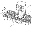
- FIG. 1 shows a perspective view of a floor structure according to the invention, with a galley installed thereon;
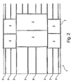
- FIG. 2 shows a horizontal projection of the floor structure according to the invention, with several floor panels adjacent to each other;
- FIG. 3 a - 3 c shows different designs of connection regions for interior equipment components on the seat rails
- FIG. 4 shows a horizontal projection of an exemplary arrangement of two galleys
- FIG. 5 shows an enlarged section in the connection region of the galley shown in FIG. 4 .
- FIG. 1 shows a section of a perspective view of the floor structure 1 according to the invention.
- a plurality of transverse girders 4 extend parallel in relation to each other, in this way spanning the fuselage (not shown) of an aircraft, which fuselage is formed by a plurality of frames.
- the transverse girders 4 comprise a plurality of openings for the purpose of installing mechanical and electrical systems, which openings at the same time result in certain weight savings.
- a plurality of seat rails 2 extend parallel in relation to each other, which seat rails 2 are normally used for fastening seats or groups of seats, as well as for locking into place interior equipment components such as, for example, galleys or lavatories.
- ten seat rails extend so as to be equidistant from each other, which seat rails are used in the standard manner for accommodating seats. Furthermore, in the exemplary embodiment shown, four further seat rails 11 are arranged in the middle region, each seat rail 11 being arranged between two standard seat rails 2 , with the purpose of the additional seat rails 11 being explained in more detail later on.
- the floor structure according to the invention further comprises several floor panels 3 , of which, however, only one is shown in FIG. 1 .
- the floor panels 3 extend over several seat rails 2 and are supported by the individual seat rails 2 .
- the floor panel 3 is supported by a total of five standard seat rails 2 , wherein for better load support and to reduce deflection between the individual seat rails 2 , further supports 11 are in place that, for example, can also comprise a seat rail profile in order to be able to fasten interior equipment components 6 therein too.
- the floor panels 3 can comprise a plurality of through-holes 5 (not shown in FIG. 1 ), through which the interior equipment components 6 of the aircraft, in the diagram by way of example the galley 6 , can be fastened to the seat rails.
- the floor panel 3 is a continuous panel that extends over the standard seat rails 2 so that as a result of this through-support effect the tensile forces as well as the deflection of the floor panel 3 between the individual seat rails 2 can be kept to a minimum.
- the exemplary embodiment shown in FIG. 1 comprises four further seat rails 11 between the middle five standard seat rails 2 , as a result of which further seat rails 11 the tensile forces and deflection of the floor panel 3 caused by the weight of the galley 6 can be reduced.
- FIG. 2 shows a horizontal projection of the floor structure 1 according to the invention, in which floor structure 1 several floor panels 3 are arranged so as to be offset in relation to each other.
- This diagram again shows that in the middle region wide floor panels 3 extend over several seat rails 2 .
- smaller floor panels 3 are arranged on the seat rails 2 so as to be offset in relation to the floor panels 3 that extend in the middle region, wherein the respective floor panels 3 abut, with the locations of the joints being tightly sealed off.
- the six floor panels 3 shown in FIG. 2 define a wet area within which a galley 6 or lavatory 6 can be arranged at any desired fastening position along the longitudinal direction of the seat rails 2 .
- the floor panels 2 comprise a plurality of through-holes 5 that are arranged along the regions by which the floor panels 3 are supported by the individual seat rails 2 so that the interior equipment components can be locked into place on the seat rails through these through-holes 5 .
- the wet area in FIG. 2 which is formed by the six floor panels 3 shown, on the circumferential side is sealed off, by the outer edges of the floor panels 3 , from the adjacent floor panels (not shown), as indicated in FIG. 2 by the circumferential edge 7 in the form of a dark line.
- FIGS. 3 a - 3 c show three different embodiments in the region of the support points of the floor panels 3 on the seat rails 2 .
- the seat rail 2 comprises a C-shaped profile, wherein in the support region of the floor panel 2 on each side a horizontal flange 8 has been formed.
- the C-shaped profile of the seat rail 2 is reinforced in vertical direction by a web 9 , as a result of which web 9 deflection in vertical direction can be reduced.
- FIG. 3 a the seat rail 2 comprises a C-shaped profile, wherein in the support region of the floor panel 2 on each side a horizontal flange 8 has been formed.
- the C-shaped profile of the seat rail 2 is reinforced in vertical direction by a web 9 , as a result of which web 9 deflection in vertical direction can be reduced.
- FIG. 3 b the floor panel 3 in the region in which it rests on the seat rail 2 comprises a through-hole 5 through which an interior equipment component 6 can be anchored, as shown in FIG. 3 b .
- This diagram shows the base of an interior equipment component 6 , which engages the C-shaped profile of the seat rail 2 with form fit by means of an engagement means 10 in order to anchor in it the interior equipment component 6 , for example a galley.
- a through-hole 5 is designed as a slot in the floor panel 3 .
- a seat is anchored in the seat rail 2 by way of a corresponding fastening means 10 which anchors the base of the seat through the through-hole 5 in the C-shaped seat rail.
- FIG. 4 shows two directly adjoining floor panels 3 .
- the two floor panels 3 rest on the seat rails 2 (not shown) which is indicated by the four rows of through-holes 5 that are arranged in the panels 3 .
- the individual through-holes 5 can, for example, have a mutual spacing of 3 inches between each other, which is dictated by the spacing of the corresponding fastening means in the seat rails 2 .
- a galley 6 is arranged, which can be fastened to either of the two floor panels 3 , at any desired position, through the through-holes 5 in the seat rails 2 (not shown).
- the galleys 6 can be moved by the above-mentioned exemplary three-inch increments and thus can assume almost any spacing in relation to each other so that the cabin design can be designed in a very individual manner.
- the two galleys 6 are, for example, spaced apart by 40 inches by an intermediate aisle, which if required can be reduced to 37, 34, 31 or still fewer inches, or can be increased to 43, 46 or more inches.
- FIG. 5 finally shows a section of FIG. 3 in the corner region of a galley 6 , wherein the fastening points of the galley 6 are more clearly shown, by means of which fastening points said galley 6 can be fastened at a 3-inch pitch to the floor panels 3 or to the seat rails 2 situated underneath them.
Priority Applications (1)
| Application Number | Priority Date | Filing Date | Title |
|---|---|---|---|
| US12/223,844 US8360363B2 (en) | 2006-02-17 | 2007-02-08 | Floor structure in an aircraft with continuous panels |
Applications Claiming Priority (6)
| Application Number | Priority Date | Filing Date | Title |
|---|---|---|---|
| US77434206P | 2006-02-17 | 2006-02-17 | |
| DE102006007469 | 2006-02-17 | ||
| DE102006007469.6 | 2006-02-17 | ||
| DE102006007469A DE102006007469A1 (de) | 2006-02-17 | 2006-02-17 | Fußbodenaufbau in einem Flugzeug mit durchlaufenden Fußbodenplatten |
| US12/223,844 US8360363B2 (en) | 2006-02-17 | 2007-02-08 | Floor structure in an aircraft with continuous panels |
| PCT/EP2007/001084 WO2007093322A1 (en) | 2006-02-17 | 2007-02-08 | Floor structure in an aircraft with continuous panels |
Publications (2)
| Publication Number | Publication Date |
|---|---|
| US20100065681A1 US20100065681A1 (en) | 2010-03-18 |
| US8360363B2 true US8360363B2 (en) | 2013-01-29 |
Family
ID=38319653
Family Applications (1)
| Application Number | Title | Priority Date | Filing Date |
|---|---|---|---|
| US12/223,844 Expired - Fee Related US8360363B2 (en) | 2006-02-17 | 2007-02-08 | Floor structure in an aircraft with continuous panels |
Country Status (10)
| Country | Link |
|---|---|
| US (1) | US8360363B2 (de) |
| EP (1) | EP1984204B1 (de) |
| JP (1) | JP2009526688A (de) |
| CN (1) | CN101384449B (de) |
| AT (1) | ATE504467T1 (de) |
| BR (1) | BRPI0707941A2 (de) |
| CA (1) | CA2636550C (de) |
| DE (2) | DE102006007469A1 (de) |
| RU (1) | RU2417906C2 (de) |
| WO (1) | WO2007093322A1 (de) |
Cited By (6)
| Publication number | Priority date | Publication date | Assignee | Title |
|---|---|---|---|---|
| US20130084792A1 (en) * | 2011-09-30 | 2013-04-04 | Airbus Operations (Sas) | Method of integrating an avionics bay and floor structure for implementation |
| US20160244186A1 (en) * | 2014-06-30 | 2016-08-25 | The Boeing Company | Flight test equipment installation system and method |
| US10351244B2 (en) | 2013-07-19 | 2019-07-16 | British Airways Plc | Aircraft passenger seat fixing systems and arrangements |
| US20200017187A1 (en) * | 2018-07-13 | 2020-01-16 | Airbus Operations Gmbh | Aircraft-floor element, aircraft zone and aircraft having an aircraft-floor element |
| US20200122840A1 (en) * | 2018-10-19 | 2020-04-23 | Airbus Operations Gmbh | Rail Arrangement For An Inner Space Of An Aircraft |
| US11135962B2 (en) * | 2016-02-18 | 2021-10-05 | Happier Camper, Inc. | Modular system for a room, for a living, work or storage area, or for other three-dimensional spaces |
Families Citing this family (9)
| Publication number | Priority date | Publication date | Assignee | Title |
|---|---|---|---|---|
| CA2640123C (en) * | 2006-02-24 | 2015-05-05 | Airbus Deutschland Gmbh | Galley and method of catering for passengers on an aircraft |
| DE102007015520A1 (de) * | 2007-03-30 | 2008-10-02 | Airbus Deutschland Gmbh | Unterbodensystem für ein Flugzeug |
| JP2013522123A (ja) * | 2010-03-23 | 2013-06-13 | ビー イー エアロスペイス,インク. | 乗客座席組立体および関連付けられた床板構造体 |
| GB201011842D0 (en) * | 2010-07-14 | 2010-09-01 | Airbus Operations Ltd | Beam |
| US9016625B2 (en) | 2011-05-11 | 2015-04-28 | The Boeing Company | Reconfigurable floorboard system |
| US9599138B2 (en) * | 2012-03-28 | 2017-03-21 | B/E Aerospace, Inc. | Aircraft monument integrated attachment device |
| CN105658518B (zh) * | 2013-10-21 | 2018-01-16 | B/E航空公司 | 模块式飞行器地板轨道适配器系统 |
| DE102015116591A1 (de) * | 2015-09-30 | 2017-03-30 | Airbus Operations Gmbh | Profil zum Verbinden einer Fußbodenstruktur und Dichtungssystem für eine Fußbodenstruktur |
| CN106986030B (zh) * | 2017-04-21 | 2019-05-21 | 陕西飞机工业(集团)有限公司 | 一种机舱滚道装置 |
Citations (34)
| Publication number | Priority date | Publication date | Assignee | Title |
|---|---|---|---|---|
| GB706614A (en) | 1948-04-14 | 1954-03-31 | Fairey Aviat Co Ltd | Improvements in or relating to convertible aircraft |
| US3396678A (en) * | 1967-05-03 | 1968-08-13 | Brownline Corp | Pallet construction |
| US3452958A (en) * | 1967-12-29 | 1969-07-01 | Heath Tecna Corp | Cargo pallet rail assembly |
| US3478995A (en) * | 1967-09-21 | 1969-11-18 | Hughes Aircraft Co | Tie-down apparatus |
| US3652050A (en) * | 1970-02-05 | 1972-03-28 | Fairchild Industries | Vehicle seat mounting system |
| US3893729A (en) * | 1974-11-18 | 1975-07-08 | Mc Donnell Douglas Corp | Convertible passenger seat |
| US3938764A (en) * | 1975-05-19 | 1976-02-17 | Mcdonnell Douglas Corporation | Frangible aircraft floor |
| US4185799A (en) * | 1978-03-14 | 1980-01-29 | Boeing Commercial Airplane Company | Aircraft partition mounting assembly |
| WO1984004948A1 (en) | 1983-06-06 | 1984-12-20 | Boeing Co | Waterproof floor panel fastening system, accessible from above |
| JPH04151399A (ja) | 1990-10-12 | 1992-05-25 | Jamco Corp | 旅客機用ラバトリーユニツト |
| US5383630A (en) | 1994-03-17 | 1995-01-24 | Teleflex Incorporated | Main deck quick change cargo system |
| FR2728860A1 (fr) | 1994-12-30 | 1996-07-05 | Renault | Plancher de vehicule automobile |
| GB2353769A (en) | 1999-09-01 | 2001-03-07 | Michael Angelo Callard | Vehicle flooring system |
| US6302358B1 (en) * | 1996-02-28 | 2001-10-16 | Societe Industrielle Et Commciale De Materiel Aeronautique | Quick Change system and method for converting an aircraft from a cargo mode to a passenger mode and vice versa |
| US6514021B2 (en) * | 2001-02-28 | 2003-02-04 | David A. Delay | T-flange engaging load bearing bed |
| RU33926U1 (ru) | 2003-07-31 | 2003-11-20 | Вайнштейн Леонид Леонидович | Устройство для крепления панелей пола самолета |
| US6659402B1 (en) * | 2002-08-07 | 2003-12-09 | The Boeing Company | Modular aircraft seat system |
| RU37688U1 (ru) | 2003-09-30 | 2004-05-10 | Открытое акционерное общество "Новосибирский авиаремонтный завод" | Фюзеляж летательного аппарата |
| EP1495946A2 (de) | 2003-07-11 | 2005-01-12 | Auto-Interieur Beheer B.V. | Fahrzeugbodenplatte, insbesondere für Kleinbusse |
| US6875916B2 (en) * | 2002-10-16 | 2005-04-05 | Airbus Deutschland Gmbh | Arrangement for laying cables in the floor area of a passenger transport aircraft |
| US20050224648A1 (en) | 2004-03-29 | 2005-10-13 | Grether Martin R | Adaptable payload apparatus and methods |
| US20050224650A1 (en) | 2004-03-29 | 2005-10-13 | Reed Raymond R | Adaptable payload processes |
| US20060049311A1 (en) * | 2004-09-08 | 2006-03-09 | Callahan Kevin S | Seat power bus with discrete connection ports |
| US7143989B2 (en) * | 2003-03-03 | 2006-12-05 | Satco, Inc. | Aircraft cargo and seating pallet |
| US7172155B2 (en) * | 2004-03-27 | 2007-02-06 | The Boeing Company | Seat interface for powered seat track cover |
| US7188805B2 (en) * | 2004-03-27 | 2007-03-13 | The Boeing Company | Continuous power bus for seat power |
| US20070080258A1 (en) * | 2005-09-06 | 2007-04-12 | Andreas Baatz | Modular seat system for a vehicle |
| US20080017755A1 (en) * | 2006-07-24 | 2008-01-24 | Ami Industries, Inc | Aircraft seat floor track fitting |
| US20090014584A1 (en) * | 2005-05-19 | 2009-01-15 | Telezygology Inc | Tracks, Power, and Data Blocks and Releasable Fastening System |
| US7607613B2 (en) * | 2004-03-29 | 2009-10-27 | The Boeing Company | Payload support track interface and fitting |
| US7618009B2 (en) * | 2004-03-20 | 2009-11-17 | Intergraph Technologies Company | Apparatus for attachment of a unit to attachment devices in a vehicle |
| US20100108808A1 (en) * | 2008-10-14 | 2010-05-06 | Airbus Operations | System for fixing |
| US20100314495A1 (en) * | 2008-01-04 | 2010-12-16 | Airbus Operations (S.A.S.) | Device for attaching a piece of furniture to the floor of an aircraft |
| US20110068226A1 (en) * | 2005-09-06 | 2011-03-24 | Airbus Deutschland Gmbh | Modular seat system for a vehicle |
-
2006
- 2006-02-17 DE DE102006007469A patent/DE102006007469A1/de not_active Withdrawn
-
2007
- 2007-02-08 WO PCT/EP2007/001084 patent/WO2007093322A1/en active Application Filing
- 2007-02-08 EP EP07703359A patent/EP1984204B1/de not_active Not-in-force
- 2007-02-08 CN CN2007800058354A patent/CN101384449B/zh not_active Expired - Fee Related
- 2007-02-08 CA CA2636550A patent/CA2636550C/en not_active Expired - Fee Related
- 2007-02-08 RU RU2008137227/11A patent/RU2417906C2/ru not_active IP Right Cessation
- 2007-02-08 US US12/223,844 patent/US8360363B2/en not_active Expired - Fee Related
- 2007-02-08 BR BRPI0707941-9A patent/BRPI0707941A2/pt not_active IP Right Cessation
- 2007-02-08 AT AT07703359T patent/ATE504467T1/de not_active IP Right Cessation
- 2007-02-08 DE DE602007013704T patent/DE602007013704D1/de active Active
- 2007-02-08 JP JP2008554636A patent/JP2009526688A/ja active Pending
Patent Citations (38)
| Publication number | Priority date | Publication date | Assignee | Title |
|---|---|---|---|---|
| GB706614A (en) | 1948-04-14 | 1954-03-31 | Fairey Aviat Co Ltd | Improvements in or relating to convertible aircraft |
| US3396678A (en) * | 1967-05-03 | 1968-08-13 | Brownline Corp | Pallet construction |
| US3478995A (en) * | 1967-09-21 | 1969-11-18 | Hughes Aircraft Co | Tie-down apparatus |
| US3452958A (en) * | 1967-12-29 | 1969-07-01 | Heath Tecna Corp | Cargo pallet rail assembly |
| US3652050A (en) * | 1970-02-05 | 1972-03-28 | Fairchild Industries | Vehicle seat mounting system |
| US3893729A (en) * | 1974-11-18 | 1975-07-08 | Mc Donnell Douglas Corp | Convertible passenger seat |
| US3938764A (en) * | 1975-05-19 | 1976-02-17 | Mcdonnell Douglas Corporation | Frangible aircraft floor |
| US4185799A (en) * | 1978-03-14 | 1980-01-29 | Boeing Commercial Airplane Company | Aircraft partition mounting assembly |
| WO1984004948A1 (en) | 1983-06-06 | 1984-12-20 | Boeing Co | Waterproof floor panel fastening system, accessible from above |
| US4577450A (en) | 1983-06-06 | 1986-03-25 | The Boeing Company | Waterproof floor panel fastening system, accessible from above |
| JPH04151399A (ja) | 1990-10-12 | 1992-05-25 | Jamco Corp | 旅客機用ラバトリーユニツト |
| US5383630A (en) | 1994-03-17 | 1995-01-24 | Teleflex Incorporated | Main deck quick change cargo system |
| FR2728860A1 (fr) | 1994-12-30 | 1996-07-05 | Renault | Plancher de vehicule automobile |
| US6302358B1 (en) * | 1996-02-28 | 2001-10-16 | Societe Industrielle Et Commciale De Materiel Aeronautique | Quick Change system and method for converting an aircraft from a cargo mode to a passenger mode and vice versa |
| GB2353769A (en) | 1999-09-01 | 2001-03-07 | Michael Angelo Callard | Vehicle flooring system |
| US6514021B2 (en) * | 2001-02-28 | 2003-02-04 | David A. Delay | T-flange engaging load bearing bed |
| US6659402B1 (en) * | 2002-08-07 | 2003-12-09 | The Boeing Company | Modular aircraft seat system |
| US6875916B2 (en) * | 2002-10-16 | 2005-04-05 | Airbus Deutschland Gmbh | Arrangement for laying cables in the floor area of a passenger transport aircraft |
| US7143989B2 (en) * | 2003-03-03 | 2006-12-05 | Satco, Inc. | Aircraft cargo and seating pallet |
| EP1495946A2 (de) | 2003-07-11 | 2005-01-12 | Auto-Interieur Beheer B.V. | Fahrzeugbodenplatte, insbesondere für Kleinbusse |
| RU33926U1 (ru) | 2003-07-31 | 2003-11-20 | Вайнштейн Леонид Леонидович | Устройство для крепления панелей пола самолета |
| RU37688U1 (ru) | 2003-09-30 | 2004-05-10 | Открытое акционерное общество "Новосибирский авиаремонтный завод" | Фюзеляж летательного аппарата |
| US7618009B2 (en) * | 2004-03-20 | 2009-11-17 | Intergraph Technologies Company | Apparatus for attachment of a unit to attachment devices in a vehicle |
| US20070164156A1 (en) * | 2004-03-27 | 2007-07-19 | The Boeing Company | Continuous power bus for seat power |
| US7172155B2 (en) * | 2004-03-27 | 2007-02-06 | The Boeing Company | Seat interface for powered seat track cover |
| US7188805B2 (en) * | 2004-03-27 | 2007-03-13 | The Boeing Company | Continuous power bus for seat power |
| US20050224648A1 (en) | 2004-03-29 | 2005-10-13 | Grether Martin R | Adaptable payload apparatus and methods |
| US7607613B2 (en) * | 2004-03-29 | 2009-10-27 | The Boeing Company | Payload support track interface and fitting |
| US20050224650A1 (en) | 2004-03-29 | 2005-10-13 | Reed Raymond R | Adaptable payload processes |
| US7207523B2 (en) * | 2004-09-08 | 2007-04-24 | The Boeing Company | Seat power bus with discrete connection ports |
| US20060049311A1 (en) * | 2004-09-08 | 2006-03-09 | Callahan Kevin S | Seat power bus with discrete connection ports |
| US20090014584A1 (en) * | 2005-05-19 | 2009-01-15 | Telezygology Inc | Tracks, Power, and Data Blocks and Releasable Fastening System |
| US7857259B2 (en) * | 2005-09-06 | 2010-12-28 | Airbus Deutschland Gmbh | Modular seat system for a vehicle |
| US20070080258A1 (en) * | 2005-09-06 | 2007-04-12 | Andreas Baatz | Modular seat system for a vehicle |
| US20110068226A1 (en) * | 2005-09-06 | 2011-03-24 | Airbus Deutschland Gmbh | Modular seat system for a vehicle |
| US20080017755A1 (en) * | 2006-07-24 | 2008-01-24 | Ami Industries, Inc | Aircraft seat floor track fitting |
| US20100314495A1 (en) * | 2008-01-04 | 2010-12-16 | Airbus Operations (S.A.S.) | Device for attaching a piece of furniture to the floor of an aircraft |
| US20100108808A1 (en) * | 2008-10-14 | 2010-05-06 | Airbus Operations | System for fixing |
Non-Patent Citations (1)
| Title |
|---|
| Zhitomirsky, Russian Journal, 6 pages (1991). (English translation of abstract only.). |
Cited By (11)
| Publication number | Priority date | Publication date | Assignee | Title |
|---|---|---|---|---|
| US20130084792A1 (en) * | 2011-09-30 | 2013-04-04 | Airbus Operations (Sas) | Method of integrating an avionics bay and floor structure for implementation |
| US9745067B2 (en) * | 2011-09-30 | 2017-08-29 | Airbus Operations (S.A.S.) | Method of integrating an avionics bay and floor structure for implementation |
| US10351244B2 (en) | 2013-07-19 | 2019-07-16 | British Airways Plc | Aircraft passenger seat fixing systems and arrangements |
| US20160244186A1 (en) * | 2014-06-30 | 2016-08-25 | The Boeing Company | Flight test equipment installation system and method |
| US9738402B2 (en) * | 2014-06-30 | 2017-08-22 | The Boeing Company | Flight test equipment installation system and method |
| US11135962B2 (en) * | 2016-02-18 | 2021-10-05 | Happier Camper, Inc. | Modular system for a room, for a living, work or storage area, or for other three-dimensional spaces |
| US11945358B2 (en) | 2016-02-18 | 2024-04-02 | Happier Camper, Inc. | Modular system for a room, for a living, work or storage area, or for other three-dimensional spaces |
| US20200017187A1 (en) * | 2018-07-13 | 2020-01-16 | Airbus Operations Gmbh | Aircraft-floor element, aircraft zone and aircraft having an aircraft-floor element |
| US11919619B2 (en) * | 2018-07-13 | 2024-03-05 | Airbus Operations Gmbh | Aircraft-floor element, aircraft zone and aircraft having an aircraft-floor element |
| US20200122840A1 (en) * | 2018-10-19 | 2020-04-23 | Airbus Operations Gmbh | Rail Arrangement For An Inner Space Of An Aircraft |
| US11708165B2 (en) * | 2018-10-19 | 2023-07-25 | Airbus Operations Gmbh | Rail arrangement for an inner space of an aircraft |
Also Published As
| Publication number | Publication date |
|---|---|
| WO2007093322A1 (en) | 2007-08-23 |
| CN101384449B (zh) | 2013-03-27 |
| EP1984204B1 (de) | 2011-04-06 |
| ATE504467T1 (de) | 2011-04-15 |
| CA2636550A1 (en) | 2008-08-23 |
| US20100065681A1 (en) | 2010-03-18 |
| DE602007013704D1 (de) | 2011-05-19 |
| BRPI0707941A2 (pt) | 2011-05-10 |
| JP2009526688A (ja) | 2009-07-23 |
| WO2007093322B1 (en) | 2007-10-18 |
| EP1984204A1 (de) | 2008-10-29 |
| DE102006007469A1 (de) | 2007-08-30 |
| CN101384449A (zh) | 2009-03-11 |
| RU2417906C2 (ru) | 2011-05-10 |
| RU2008137227A (ru) | 2010-03-27 |
| CA2636550C (en) | 2014-07-15 |
Similar Documents
| Publication | Publication Date | Title |
|---|---|---|
| US8360363B2 (en) | Floor structure in an aircraft with continuous panels | |
| EP2179920B1 (de) | Flugzeugkabinenbodenstrukturen, Systeme und Verfahren | |
| US7281685B2 (en) | Flush-top seat mounting rail for passenger aircraft | |
| CA2591161C (en) | Arrangement of line connections for installations in an aircraft passenger cabin | |
| US20090236471A1 (en) | Non-Protruding Seat Track Apparatus and Methods | |
| US20150108273A1 (en) | Modular aircraft floor track adapter system | |
| WO2007057191A1 (en) | Attachment structure for affixing interior equipment components of an aircraft passenger cabin | |
| US8453970B2 (en) | Under-floor system for an aircraft | |
| US20100252684A1 (en) | Fuselage cell structure of an airplane for the simplified installation and attachment of fasteners for fastening conduits | |
| GB2435251A (en) | Airplane floor assembly | |
| US7093797B2 (en) | Adaptable payload apparatus and methods | |
| US11541981B2 (en) | Method for installing system components in a portion of an aircraft fuselage | |
| US20090014586A1 (en) | Light rail system for powered introduction of large loads in a structure | |
| EP2825449B1 (de) | Flugzeugrumpfstruktur mit transversalen profilen und einer tragwerkstruktur | |
| US20170158334A1 (en) | Modular rail system for fastening of furnishing items to a floor of a vehicle cabin | |
| US20160200417A1 (en) | Floor arrangement with curved floor panels for an aircraft | |
| US20230002062A1 (en) | Mounting rail arrangement for an aircraft floor, floor structure and aircraft having the same | |
| US20240109641A1 (en) | Floor arrangement in an aircraft |
Legal Events
| Date | Code | Title | Description |
|---|---|---|---|
| AS | Assignment |
Owner name: AIRBUS DEUTSCHLAND GMBH,GERMANY Free format text: ASSIGNMENT OF ASSIGNORS INTEREST;ASSIGNORS:GONNSEN, JOHANNES;KOOK, MANFRED;FOKKEN, MARKUS;AND OTHERS;SIGNING DATES FROM 20080814 TO 20080829;REEL/FRAME:022486/0829 Owner name: AIRBUS DEUTSCHLAND GMBH, GERMANY Free format text: ASSIGNMENT OF ASSIGNORS INTEREST;ASSIGNORS:GONNSEN, JOHANNES;KOOK, MANFRED;FOKKEN, MARKUS;AND OTHERS;SIGNING DATES FROM 20080814 TO 20080829;REEL/FRAME:022486/0829 |
|
| AS | Assignment |
Owner name: AIRBUS OPERATIONS GMBH, GERMANY Free format text: CHANGE OF NAME;ASSIGNOR:AIRBUS DEUTSCHLAND GMBH;REEL/FRAME:026360/0849 Effective date: 20090602 |
|
| STCF | Information on status: patent grant |
Free format text: PATENTED CASE |
|
| FPAY | Fee payment |
Year of fee payment: 4 |
|
| FEPP | Fee payment procedure |
Free format text: MAINTENANCE FEE REMINDER MAILED (ORIGINAL EVENT CODE: REM.); ENTITY STATUS OF PATENT OWNER: LARGE ENTITY |
|
| LAPS | Lapse for failure to pay maintenance fees |
Free format text: PATENT EXPIRED FOR FAILURE TO PAY MAINTENANCE FEES (ORIGINAL EVENT CODE: EXP.); ENTITY STATUS OF PATENT OWNER: LARGE ENTITY |
|
| STCH | Information on status: patent discontinuation |
Free format text: PATENT EXPIRED DUE TO NONPAYMENT OF MAINTENANCE FEES UNDER 37 CFR 1.362 |
|
| FP | Lapsed due to failure to pay maintenance fee |
Effective date: 20210129 |