US8337572B2 - Battery and method for producing the same - Google Patents
Battery and method for producing the same Download PDFInfo
- Publication number
- US8337572B2 US8337572B2 US12/739,820 US73982009A US8337572B2 US 8337572 B2 US8337572 B2 US 8337572B2 US 73982009 A US73982009 A US 73982009A US 8337572 B2 US8337572 B2 US 8337572B2
- Authority
- US
- United States
- Prior art keywords
- electrode
- current collector
- collector plate
- core member
- battery
- Prior art date
- Legal status (The legal status is an assumption and is not a legal conclusion. Google has not performed a legal analysis and makes no representation as to the accuracy of the status listed.)
- Expired - Fee Related, expires
Links
Images


Classifications
-
- H—ELECTRICITY
- H01—ELECTRIC ELEMENTS
- H01M—PROCESSES OR MEANS, e.g. BATTERIES, FOR THE DIRECT CONVERSION OF CHEMICAL ENERGY INTO ELECTRICAL ENERGY
- H01M10/00—Secondary cells; Manufacture thereof
- H01M10/04—Construction or manufacture in general
- H01M10/0431—Cells with wound or folded electrodes
-
- H—ELECTRICITY
- H01—ELECTRIC ELEMENTS
- H01M—PROCESSES OR MEANS, e.g. BATTERIES, FOR THE DIRECT CONVERSION OF CHEMICAL ENERGY INTO ELECTRICAL ENERGY
- H01M10/00—Secondary cells; Manufacture thereof
- H01M10/04—Construction or manufacture in general
- H01M10/0413—Large-sized flat cells or batteries for motive or stationary systems with plate-like electrodes
-
- H—ELECTRICITY
- H01—ELECTRIC ELEMENTS
- H01M—PROCESSES OR MEANS, e.g. BATTERIES, FOR THE DIRECT CONVERSION OF CHEMICAL ENERGY INTO ELECTRICAL ENERGY
- H01M10/00—Secondary cells; Manufacture thereof
- H01M10/04—Construction or manufacture in general
- H01M10/0436—Small-sized flat cells or batteries for portable equipment
-
- H—ELECTRICITY
- H01—ELECTRIC ELEMENTS
- H01M—PROCESSES OR MEANS, e.g. BATTERIES, FOR THE DIRECT CONVERSION OF CHEMICAL ENERGY INTO ELECTRICAL ENERGY
- H01M10/00—Secondary cells; Manufacture thereof
- H01M10/05—Accumulators with non-aqueous electrolyte
- H01M10/052—Li-accumulators
- H01M10/0525—Rocking-chair batteries, i.e. batteries with lithium insertion or intercalation in both electrodes; Lithium-ion batteries
-
- H—ELECTRICITY
- H01—ELECTRIC ELEMENTS
- H01M—PROCESSES OR MEANS, e.g. BATTERIES, FOR THE DIRECT CONVERSION OF CHEMICAL ENERGY INTO ELECTRICAL ENERGY
- H01M10/00—Secondary cells; Manufacture thereof
- H01M10/05—Accumulators with non-aqueous electrolyte
- H01M10/058—Construction or manufacture
- H01M10/0585—Construction or manufacture of accumulators having only flat construction elements, i.e. flat positive electrodes, flat negative electrodes and flat separators
-
- H—ELECTRICITY
- H01—ELECTRIC ELEMENTS
- H01M—PROCESSES OR MEANS, e.g. BATTERIES, FOR THE DIRECT CONVERSION OF CHEMICAL ENERGY INTO ELECTRICAL ENERGY
- H01M10/00—Secondary cells; Manufacture thereof
- H01M10/05—Accumulators with non-aqueous electrolyte
- H01M10/058—Construction or manufacture
- H01M10/0587—Construction or manufacture of accumulators having only wound construction elements, i.e. wound positive electrodes, wound negative electrodes and wound separators
-
- H—ELECTRICITY
- H01—ELECTRIC ELEMENTS
- H01M—PROCESSES OR MEANS, e.g. BATTERIES, FOR THE DIRECT CONVERSION OF CHEMICAL ENERGY INTO ELECTRICAL ENERGY
- H01M50/00—Constructional details or processes of manufacture of the non-active parts of electrochemical cells other than fuel cells, e.g. hybrid cells
- H01M50/50—Current conducting connections for cells or batteries
- H01M50/531—Electrode connections inside a battery casing
- H01M50/538—Connection of several leads or tabs of wound or folded electrode stacks
-
- H—ELECTRICITY
- H01—ELECTRIC ELEMENTS
- H01M—PROCESSES OR MEANS, e.g. BATTERIES, FOR THE DIRECT CONVERSION OF CHEMICAL ENERGY INTO ELECTRICAL ENERGY
- H01M50/00—Constructional details or processes of manufacture of the non-active parts of electrochemical cells other than fuel cells, e.g. hybrid cells
- H01M50/50—Current conducting connections for cells or batteries
- H01M50/531—Electrode connections inside a battery casing
- H01M50/54—Connection of several leads or tabs of plate-like electrode stacks, e.g. electrode pole straps or bridges
-
- H—ELECTRICITY
- H01—ELECTRIC ELEMENTS
- H01M—PROCESSES OR MEANS, e.g. BATTERIES, FOR THE DIRECT CONVERSION OF CHEMICAL ENERGY INTO ELECTRICAL ENERGY
- H01M2220/00—Batteries for particular applications
- H01M2220/10—Batteries in stationary systems, e.g. emergency power source in plant
-
- H—ELECTRICITY
- H01—ELECTRIC ELEMENTS
- H01M—PROCESSES OR MEANS, e.g. BATTERIES, FOR THE DIRECT CONVERSION OF CHEMICAL ENERGY INTO ELECTRICAL ENERGY
- H01M2220/00—Batteries for particular applications
- H01M2220/20—Batteries in motive systems, e.g. vehicle, ship, plane
-
- H—ELECTRICITY
- H01—ELECTRIC ELEMENTS
- H01M—PROCESSES OR MEANS, e.g. BATTERIES, FOR THE DIRECT CONVERSION OF CHEMICAL ENERGY INTO ELECTRICAL ENERGY
- H01M2220/00—Batteries for particular applications
- H01M2220/30—Batteries in portable systems, e.g. mobile phone, laptop
-
- H—ELECTRICITY
- H01—ELECTRIC ELEMENTS
- H01M—PROCESSES OR MEANS, e.g. BATTERIES, FOR THE DIRECT CONVERSION OF CHEMICAL ENERGY INTO ELECTRICAL ENERGY
- H01M50/00—Constructional details or processes of manufacture of the non-active parts of electrochemical cells other than fuel cells, e.g. hybrid cells
- H01M50/50—Current conducting connections for cells or batteries
- H01M50/531—Electrode connections inside a battery casing
- H01M50/534—Electrode connections inside a battery casing characterised by the material of the leads or tabs
-
- H—ELECTRICITY
- H01—ELECTRIC ELEMENTS
- H01M—PROCESSES OR MEANS, e.g. BATTERIES, FOR THE DIRECT CONVERSION OF CHEMICAL ENERGY INTO ELECTRICAL ENERGY
- H01M50/00—Constructional details or processes of manufacture of the non-active parts of electrochemical cells other than fuel cells, e.g. hybrid cells
- H01M50/50—Current conducting connections for cells or batteries
- H01M50/531—Electrode connections inside a battery casing
- H01M50/536—Electrode connections inside a battery casing characterised by the method of fixing the leads to the electrodes, e.g. by welding
-
- Y—GENERAL TAGGING OF NEW TECHNOLOGICAL DEVELOPMENTS; GENERAL TAGGING OF CROSS-SECTIONAL TECHNOLOGIES SPANNING OVER SEVERAL SECTIONS OF THE IPC; TECHNICAL SUBJECTS COVERED BY FORMER USPC CROSS-REFERENCE ART COLLECTIONS [XRACs] AND DIGESTS
- Y02—TECHNOLOGIES OR APPLICATIONS FOR MITIGATION OR ADAPTATION AGAINST CLIMATE CHANGE
- Y02E—REDUCTION OF GREENHOUSE GAS [GHG] EMISSIONS, RELATED TO ENERGY GENERATION, TRANSMISSION OR DISTRIBUTION
- Y02E60/00—Enabling technologies; Technologies with a potential or indirect contribution to GHG emissions mitigation
- Y02E60/10—Energy storage using batteries
-
- Y—GENERAL TAGGING OF NEW TECHNOLOGICAL DEVELOPMENTS; GENERAL TAGGING OF CROSS-SECTIONAL TECHNOLOGIES SPANNING OVER SEVERAL SECTIONS OF THE IPC; TECHNICAL SUBJECTS COVERED BY FORMER USPC CROSS-REFERENCE ART COLLECTIONS [XRACs] AND DIGESTS
- Y02—TECHNOLOGIES OR APPLICATIONS FOR MITIGATION OR ADAPTATION AGAINST CLIMATE CHANGE
- Y02P—CLIMATE CHANGE MITIGATION TECHNOLOGIES IN THE PRODUCTION OR PROCESSING OF GOODS
- Y02P70/00—Climate change mitigation technologies in the production process for final industrial or consumer products
- Y02P70/50—Manufacturing or production processes characterised by the final manufactured product
-
- Y—GENERAL TAGGING OF NEW TECHNOLOGICAL DEVELOPMENTS; GENERAL TAGGING OF CROSS-SECTIONAL TECHNOLOGIES SPANNING OVER SEVERAL SECTIONS OF THE IPC; TECHNICAL SUBJECTS COVERED BY FORMER USPC CROSS-REFERENCE ART COLLECTIONS [XRACs] AND DIGESTS
- Y10—TECHNICAL SUBJECTS COVERED BY FORMER USPC
- Y10T—TECHNICAL SUBJECTS COVERED BY FORMER US CLASSIFICATION
- Y10T29/00—Metal working
- Y10T29/49—Method of mechanical manufacture
- Y10T29/49002—Electrical device making
- Y10T29/49108—Electric battery cell making
- Y10T29/49115—Electric battery cell making including coating or impregnating
Definitions
- the present invention relates to a battery which is suitable as a power source for driving a variety of apparatus, and particularly relates to a battery having a current collecting structure that exhibits low resistance and is appropriate for discharging at a large current, and a method for producing the battery.
- Secondary batteries such as non-aqueous electrolyte secondary batteries, nickel-metal hydride secondary batteries, and nickel-cadmium secondary batteries are used as a power source for driving a variety of apparatus. Secondary batteries have various uses from consumer apparatus exemplified by cellular phones to electric vehicles, electric tools and the like. Above all, non-aqueous electrolyte secondary batteries attract a great attention because they are small-sized, light-weight, and have a high energy density. In recent years, development of the secondary batteries having a higher energy density and a higher output has been increased.
- a secondary battery used for consumer apparatus for example a non-aqueous electrolyte secondary battery includes in general a metallic battery case having a bottom for housing an electrode group and an electrolyte, and a sealing plate for sealing an opening of the battery case.
- the sealing plate includes a metallic filter serving as an internal terminal and a metallic cap serving as an external terminal, and a safety valve and a PTC element are usually interposed between these.
- the safety valve is composed of a metal thin film and an explosion-proof valve, for example.
- the sealing plate is formed by caulking the periphery of the metallic filter on the periphery of the metallic cap, the PTC element, and the safety valve with an inner gasket made of resin interposed therebetween.
- the metal thin film and the explosion-proof valve constituting the safety valve are welded at respective central portions and are electrically connected.
- the metal thin film breaks to block the current path.
- gas inside the battery is discharged outside.
- PTL 1 proposes to form a current collector portion by sandwiching a tap portion (end portion) of a metal material (core member) constituting an electrode by a conductive member and welding the end portion to the conductive member.
- PTL 2 proposes a battery in which an end portion of an electrode core member is made to protrude from an electrode group and the protruding portion is connected to a current collector plate.
- the current collector plate has a cutaway groove portion, and the current collector plate and a tip of the protruding portion are connected to each other on the periphery of the groove portion. According to this proposition, it seems that the connection area of the current collector plate with the protruding portion can be set smaller and the strength of the connection portion can be increased.
- PTLs 1 and 2 indicate an arc welding method, a laser welding method, and an electron beam method as a means for welding an electrode group to a current collector member (conductive member or current collector plate).
- a current collector member conductive member or current collector plate.
- tools for fixing the current collector member may possibly be displaced from a prescribed location, and an energy source such as an arc may not fly to an intended direction.
- an electrode core member and a current collector member are welded together at a point away from an intended welding portion.
- the present invention has an object to ensure welding of the current collector plate to the electrode plate at an intended connection portion.
- the present invention relates to a battery comprising: an electrode group comprising a first electrode, a second electrode, and a separator interposed therebetween that are wound or laminated; and a first current collector plate electrically connected to the first electrode, wherein the first electrode includes a first electrode core member and a first electrode material mixture layer formed on the first electrode core member; the second electrode includes a second electrode core member and a second electrode material mixture layer formed on the second electrode core member; one end portion of the first electrode is protruding from an end portion of the second electrode and an end portion of the separator at one end surface of the electrode group, and the protruding end portion of the first electrode has an exposed portion of the first electrode core member; the exposed portion of the first electrode core member is welded to a connection portion on one surface of the first current collector plate; and an insulating layer is formed in an area except for a reverse face portion of the connection portion on the other surface of the first current collector plate.
- the present invention relates to a battery comprising: an electrode group comprising a first electrode, a second electrode, and a separator interposed therebetween that are wound or laminated; and a first current collector plate electrically connected to the first electrode and a second current collector plate electrically connected to the second electrode, wherein the first electrode includes a first electrode core member and a first electrode material mixture layer formed on the first electrode core member; the second electrode includes a second electrode core member and a second electrode material mixture layer formed on the second electrode core member; one end portion of the first electrode is protruding from an end portion of the second electrode and an end portion of the separator at one end surface of the electrode group; the protruding end portion of the first electrode has an exposed portion of the first electrode core member; the protruding end portion of the first electrode has an exposed portion of the first electrode core member; one end portion of the second electrode is protruding from an end portion of the first electrode and an end portion of the separator at the other end surface of the electrode group; the protruding end portion of
- the present invention relates to a method for producing a battery including the steps of:
- the present invention relates to a method for producing a battery including the steps of:
- first current collector plate including an intended connection portion (first intended connection portion) on one surface thereof and an insulating layer formed in an area except for a reverse face portion of the first intended connection portion on the other surface thereof, and a second current collector plate including an intended connection portion (second intended connection portion) on one surface thereof and an insulating layer formed in an area except for a reverse face portion of the second intended connection portion on the other surface thereof;
- an insulating layer may also be formed on a part of the reverse face portion of the connection portion (intended connection portion). Further, a certain effect can be obtained if an insulating layer is formed on at least a part of the area except for the reverse face portion of the connection portion (intended connection portion).
- an insulating layer is also formed on a peripheral side surface of the current collector plate.
- the insulating layer on the peripheral side surface not only prevents scattering of the arc but also serves to prevent electrical connection between the battery case and the current collector plate.
- the present invention relates to a method for producing a battery including the steps of:
- the present invention also relates to a method for producing a battery including the steps of:
- the thickness of the insulating layer is preferably 5 ⁇ m or more.
- the insulating layer may contain ceramic particles.
- first current collector plate and the second current collector plate have concaves and convexes in a corrugated form in the thickness direction.
- connection portions of the first current collector plate and the second current collector plate are provided on a concave face of the concaves and convexes.
- the present invention it is possible to ensure welding of the current collector plate to the electrode group in an intended connection portion. That is, it is possible to ensure connection of the exposed portion of the first electrode core member to the connection portion of the first current collector plate, thereby to obtain a battery having a high reliability.
- FIG. 1A is a view showing a configuration of a first electrode.
- FIG. 1B is a view showing a configuration of a second electrode.
- FIG. 1C is a perspective view showing an example of a wound-type electrode group.
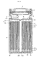
- FIG. 2 is a vertical sectional view of a battery in accordance with an embodiment of the present invention.
- FIG. 3 is a sectional view of a current collector plate in accordance with an embodiment of the present invention.
- FIG. 4 is a sectional view of an insulating mask in accordance with an embodiment of the present invention.
- FIG. 5 is a vertical sectional view of a battery in accordance with another embodiment of the present invention.
- FIG. 6 is a sectional view of a current collector in accordance with another embodiment of the present invention.
- FIG. 7 is a sectional view of a current collector plate in accordance with still another embodiment of the present invention.
- FIG. 8 is a view showing a pattern of an intended connection portion disposed on the current collector plate.
- FIGS. 1A to 1C are schematic structural view of an electrode group in accordance with this embodiment.
- FIG. 2 is a schematic vertical sectional view of a battery in accordance with this embodiment.
- the battery in accordance with this embodiment has a structure with no tab and includes a cylindrical electrode group 4 , a first current collector plate 10 in a disk form, and a second current collector plate 20 in a disk form.
- a first electrode 1 and a second electrode 2 are connected respectively to the first current collector plate 10 and the second current collector plate 20 with no tab interposed.
- the electrode group 4 is constituted by winding the first electrode 1 in a belt form and the second electrode 2 in a belt form with a separator 3 in a belt form interposed therebetween.
- the first electrode 1 includes a first electrode core member in a sheet form and first electrode material mixture layers 1 b formed on both surfaces thereof. An exposed portion 1 a of the first electrode core member is formed on one end portion along the longitudinal direction of the first electrode 1 .
- the second electrode 2 includes a second electrode core member and second electrode material mixture layers 2 b formed on both surfaces thereof. An exposed portion 2 a of the second electrode core member is formed on one end portion along the longitudinal direction of the second electrode 2 .
- the exposed portions of the respective electrode core members are portions to be welded to connection portions of the current collector plates.
- the first electrode and the second electrode are laminated and wound with the separator interposed therebetween with the exposed portion 1 a of the first electrode core member and the exposed portion 2 a of the second electrode core member disposed opposite to each other.
- the exposed portion 1 a of the first electrode core member is disposed on one end surface, that is, one bottom surface of the electrode group 4 in a column form, and the exposed portion 2 a of the second electrode core member is disposed on the other bottom surface thereof.
- the exposed portion 1 a of the first electrode core member is protruded outside the end portion of the second electrode 2 and the end portion the separator 3 on one bottom surface of the electrode group 4 .
- the exposed portion 2 a of the second electrode core member is protruded outside the end portion of the first electrode 1 and the end portion of the separator 3 on the other bottom surface of the electrode group 4 .
- the end portion of the separator 3 is protruded outside the end portion of the second electrode 2 on the bottom surface of the electrode group on which the exposed portion 1 a of the first electrode core member is disposed.
- the end portion of the separator 3 is protruded outside the end portion of the first electrode 1 on the bottom surface of the electrode group on which the exposed portion 2 a of the second electrode core member is disposed.
- the exposed portion 1 a of the first electrode core member is welded to a connection portion 10 a on one surface of the first current collector plate 10 .
- An insulating layer 14 is formed on the other surface of the first current collector plate 10 .
- the exposed portion 2 a of the second electrode core member is welded to a connection portion 20 a on one surface of the second current collector plate 20 .
- An insulating layer 24 is formed on the other surface of the second current collector plate 20 .
- the first current collector plate 10 and the second current collector plate 20 are both metallic and have a disk form. It is preferable that the current collector plate connected to the positive electrode is made of a metal such as aluminum and that the current collector plate connected to the negative electrode is made of a metal such as copper and iron. Although the shape of the current collector plate is not particularly restricted, it is preferable that the current collector plate has a shape such that it covers entirely the end surface of the electrode group to which it is to be connected. Therefore, the shape of the current collector plate is different according to the shape of the end surface of the electrode group. The thickness of the current collector plate is not particularly restricted and is 0.5 to 2 mm, for example. One or more through holes may be formed on the current collector plate.
- FIG. 3 is an enlarged view of the first current collector plate 10 .
- a through hole 10 b is formed in the center of the first current collector plate.
- the through hole 10 b has an action of accelerating discharge of gas and facilitating immersion of the electrode group with the electrolyte. For example, gas accumulated in the bottom portion of the battery passes through a hollow portion of the electrode group and flows out from the through hole of the current collector plate outside the electrode group.
- One surface (surface to be connected to the electrode group 4 ) of the first current collector plate has the connection portion 10 a connected to the exposed portion 1 a of the first electrode core member 1 a , and an insulating layer 14 is formed on the other surface of the first current collector plate except for a reverse face portion 15 of the connection portion 10 a.
- the first current collector plate is disposed on one bottom surface of the electrode group 4 such that the through hole 10 b communicates with the hollow portion of the electrode group 4 . It is preferable that the bottom surface of the electrode group 4 is covered completely when viewed from the first current collector plate side. Welding is performed in this state. That is, the exposed portion 1 a of the first electrode core member is brought in contact with the connection portion 10 a of the first current collector plate, and energy is applied by an arc discharge etc. from the side on which the insulating layer 14 is formed. At this time, the arc is not applied to the portion on which the insulating layer 14 is formed.
- the arc is applied intensively to the reverse face portion 15 of the connected portion 10 a , that is, the metal surface of the first current collector plate on which the insulating layer is not disposed. As a consequence, it is possible to limit the connection portion 10 a to an intended portion, and thereby the welding is completed efficiently.
- the second current collector plate 20 has substantially the same structure as the first current collector plate 10 and includes a connection portion 20 a connected to the exposed portion 2 a of the second electrode core member and an insulating layer 24 formed in an area except for a reverse face portion 25 of the connection portion 20 a .
- the second current collector plate 20 has no through hole in the center but has a central welding portion 20 b serving as a connection portion connected to a bottom surface of a battery case 5 .
- the structure of the second current collector plate is not particularly limited.
- the second current collector plate 20 may have a through hole and may not have the central welding portion 20 b.
- connection portion 10 a of the first current collector plate and the connection portion 20 a of the second current collector plate can be set voluntarily by a formation pattern of the insulating layer.
- a welding method such as an arc welding, a laser welding, and an electron beam welding can be employed.
- an arc welding examples include TIG (tungsten inert gas) welding, MIG welding, MAG welding, and carbonic gas arc welding, and TIG welding is particularly preferable.
- TIG welding is particularly effective when the current collector plate is composed of copper, aluminum etc.
- the thickness of the electrode core member ranges from about 10 to 30 ⁇ m, for example. Therefore, TIG welding is preferable from the viewpoint of inhibiting defects such as short circuiting caused by bending of the electrode core member.
- the thickness of the insulating layer formed on the surface of the current collector plate is preferably more than 5 ⁇ m, and more preferably 10 to 100 ⁇ m. In the case where the thickness of the insulating layer is less than 5 ⁇ m, the arc may not possibly be applied efficiently to the metal face avoiding the insulating layer during the arc welding.
- the insulating layer preferably includes ceramic particles. Ceramics are preferable as a material for the insulating layer because of having a favorable insulating property, a high melting point, and a low reactivity. Examples of the usable ceramics include oxides, carbides, nitrides, and borides. Specifically, alumina, magnesia etc. can be used without any particular restriction. Although the average particle diameter of the ceramic particles is not particularly restricted, it ranges preferably from 0.1 to 2 ⁇ m.
- the first electrode is prepared.
- the first electrode 1 as shown in FIG. 1A can be obtained by forming the first electrode material mixture layer 1 b on the first electrode core member except for the exposed portion 1 a.
- the second electrode is prepared.
- the second electrode 2 as shown in FIG. 1B can be obtained by forming the second electrode material mixture layer 2 b on the second electrode core member except for the exposed portion 2 a . However, it is not essential to leave the exposed portion 2 a of the second electrode core member.
- the electrode core member is metallic, and in the case of the positive electrode, aluminum, nickel, magnesium etc. are used; in the case of the negative electrode, copper, iron, nickel etc. are used.
- the shape of the electrode core member is not particularly restricted, it is for example a foil or a sheet in a belt form. In this case, the exposed portion of the first electrode core member is formed on an end portion along the longitudinal direction of the electrode in the belt form.
- the foil or the sheet may be composed of a porous material.
- An electrode group in which the exposed portion of the first electrode core member is protruding from the end portion of the second electrode and the end portion of the separator on one end surface is constituted by winding or laminating the first electrode and the second electrode with the separator interposed therebetween.
- the electrode group 4 as shown in FIG. 1C is formed by disposing the first electrode 1 , the second electrode 2 , and the separator 3 such that the exposed portion 1 a of the first electrode core member and the exposed portion 2 a of the second electrode core member are placed opposite to each other and that they are protruding from the end portion of the separator 3 , and winding these in a spiral form.
- the separator 3 may be a microporous film made of a resin, a porous insulating film including a filler such as a metal oxide and a binder, or a laminate of a microporous film made of a resin and the porous insulating film.
- a current collector plate having an intended connection portion on one surface and an insulation layer formed on the other surface except for the portion overlapping the intended connection portion is prepared, and (v) an arc is applied from the other surface of the current collector plate thereby to weld the exposed portion of the electrode core member to the intended connection portion of the current collector plate.
- the first current collector plate 10 and the second current collector plate 20 as shown in FIGS. 2 and 3 are prepared.
- insulating layers 14 and 24 are formed, partially leaving metal surfaces 15 and 25 .
- Examples of a method for forming the insulating layers 14 and 24 include application, spray, sputtering etc. of an insulating material.
- an insulating paste is prepared by mixing ceramic particles, a binder, and a liquid component, and the insulating paste is applied onto a prescribed surface of the current collector plate and dried.
- the method is not limited thereto as long as it enables uniform formation of an insulating layer.
- the first current collector plate 10 is disposed on one end surface of the electrode group 4 with the insulating layer 14 placed outside. Subsequently, the first current collector plate 10 and the exposed portion 1 a of the first electrode core member are welded together by an arc welding. Specifically, an electrode for welding is disposed away from the reverse face portion 15 of the connection portion 10 a of the first current collector plate, and an arc is applied to melt the connection portion 10 a of the first current collector plate. By using an arc welding such as TIG welding, the arc is surely applied to the metal surface on which the insulating layer 14 is not formed, which can melt the connection portion 10 a . Thereby, the first current collector plate 10 and the electrode group 4 can be connected to each other.
- an arc welding such as TIG welding
- the second current collector 20 is disposed on the other end surface of the electrode group 4 with the insulating layer 24 placed outside. Then, by the same operation as in the case of the first current collector plate, the second current collector plate 20 and the electrode group 4 are connected to each other.
- the electrode group 4 to which both of the current collector plates are welded are housed in the battery case 5 .
- the second current collector plate 20 is brought in contact with the bottom surface of the battery case 5 .
- the first current collector plate 10 is connected to a sealing plate 7 via a lead 6 .
- a non-aqueous electrolyte is poured into the battery case 5 , and the battery is sealed by caulking an opening end of the battery case on a gasket 8 provided in the periphery of the sealing plate 7 .
- the battery case 5 has an inwardly recessed portion, and an insulating member 17 for ensuring insulation with the first current collector plate 10 is disposed in the recessed portion.
- the insulating layer is formed on the first current collector plate 10 and the second current collector plate 20 except for the reverse face portion of the connection portion connected to the electrode group. Therefore, when welding the current collector plate to the electrode group, the arc is applied only to the metal surface on which the insulating layer is not formed. In this case, the arc is surely applied to the metal surface of the current collector plate. Consequently, the current collector plate and the electrode plate can be connected in a desired connection portion as long as a relative positional relation of the electrode group with the current collector plate is fixed even if arrangement location of the electrode for welding is somewhat displaced. As a consequence, connection defects of the electrode group with the current collector plate can be greatly reduced, thereby preventing a decrease in the yield.
- FIG. 4 is a sectional view of an insulating mask used in a method for producing a battery in accordance with this embodiment.
- FIG. 5 is a vertical sectional view of a battery produced in accordance with the production method of this embodiment.
- At least one of the first current collector plate and the second current collector plate has a structure different from that of the first embodiment, and the method for welding the current collector plate to the electrode group is also different.
- the battery as shown in FIG. 5 has the same structure as that of the first embodiment except that no insulating layer is formed on the first current collector plate 10 and the second current collector plate 20 .
- an insulating mask 27 is disposed onto a reverse face of the connection portion of the current collector plate with the electrode group 4 .
- the insulating mask 27 has one or more opening 28 on the location corresponding to the intended connection portion of the current collector plate.
- the exposed portion of the electrode core member is welded to the intended connection portion of the current collector plate by attaching one surface of each current collector plate to an end surface of the electrode group and applying an arc from the other surface via the insulating mask.
- the arc can be applied intensively into the opening 28 of the insulating mask by using an arc welding such as TIG welding.
- TIG welding such as TIG welding.
- the current collector plate and the electrode group can be connected at a desired connection portion.
- connection defects of the electrode group with the current collector plate can be greatly reduced, thereby to prevent a decrease in the yield.
- the insulating mask 27 is removed from the other surface of the current collector plate.
- a current collector plate in accordance with this embodiment has a structure different from that of the first embodiment and the second embodiment.
- FIG. 6 is a sectional view of an example of the current collector plate in accordance with this embodiment.
- a current collector plate 30 has concaves and convexes in a corrugated form in the thickness direction. In the case where the electrode group is cylindrical and the current collector plate is in a disk form, it is preferable that concaves and convexes are formed concentrically when viewed from one surface or the other surface of the current collector plate.
- the configuration of the concaves and convexes viewed from one surface or the other surface of the current collector plate is not particularly limited as long as the configuration thereof is in accordance with the configuration of the exposed portion of the electrode core member protruding from the end surface of the electrode group.
- the shape of the wave in the cross section is not particularly limited, and for example a tip of a convex portion and a bottom of a concave portion may be pointed acutely, or may be curved.
- An insulating layer 34 is formed on one surface of the current collector plate 30 except for the vicinity of a tip 33 of a convex face 30 b .
- the exposed portion of the electrode core member protruding from the end surface of the electrode group is accommodated in a concave 30 a on the other surface of the current collector plate, and the exposed portion of the electrode core member and the concave of the current collector plate are engaged with each other. In consequence, not only positioning of the exposed portion of the electrode core member with the connection portion of the current collector plate is facilitated, but also welding strength is increased thereby to improve current collection efficiency.
- An arc welding using such a current collector plate ensures welding at a desired connection portion 35 because an arc flies intensively onto the vicinity of the tip 33 of the convex face 30 b.
- a current collector plate in accordance with this embodiment has the same structure as that of the third embodiment except for not including an insulating layer.
- FIG. 7 is a sectional view of an example of the current collector plate in accordance with this embodiment.
- a current collector plate 50 has concaves and convexes in a corrugated form in the thickness direction. The exposed portion of the electrode core member protruding from the end surface of the electrode group is accommodated in a concave 50 a on the other surface of the current collector plate, and the exposed portion of the electrode core member and the concave of the current collector plate are engaged with each other.
- an arc is applied to the current collector plate via an insulating mask having an opening corresponding to the vicinity of a tip 53 on the convex, that is, a connection portion 55 .
- the arc is not applied to the insulating mask and applied intensively to the vicinity of the tip 53 of the convex that is exposed at the opening. Therefore, it is possible to ensure welding at the intended connection portion 55 .
- a positive electrode material mixture paste was prepared by mixing 85 parts by weight of a powder of lithium cobaltate as a positive electrode active material, 10 parts by weight of a carbon powder as a conductive agent, 5 parts by weight of polyvinylidene fluoride (PVDF) as a binder, and an appropriate amount of N-methyl-2-pyrrolidone (NMP).
- PVDF polyvinylidene fluoride
- the positive electrode material mixture paste was applied onto both surfaces of a positive electrode core member made of an aluminum foil having a thickness of 15 ⁇ m and a width of 56 mm.
- a positive electrode core member made of an aluminum foil having a thickness of 15 ⁇ m and a width of 56 mm.
- an exposed portion of the positive electrode core member having a width of 6 mm was left on one end portion along the longitudinal direction of the positive electrode core member, and the width of an applied film of the positive electrode material mixture paste was 50 mm. Thereafter, the applied films were dried and rolled, thereby to obtain a positive electrode having a thickness of 150 ⁇ m.
- a negative electrode material mixture paste was prepared by mixing 95 parts by weight of an artificial graphite powder, 5 parts by weight of PVDF as a binder, and an appropriate amount of NMP.
- the negative electrode material mixture paste was applied onto both surfaces of a negative electrode core member made of a copper foil having a thickness of 10 ⁇ m and a width of 57 mm.
- a negative electrode core member made of a copper foil having a thickness of 10 ⁇ m and a width of 57 mm.
- an exposed portion of the negative electrode core member having a width of 5 mm was left on one end portion along the longitudinal direction of the negative electrode core member, and the width of an applied film of the positive electrode material mixture paste was 52 mm. Thereafter, the applied films were dried and rolled, thereby to obtain a negative electrode having a thickness of 160 ⁇ m.
- An electrode group is produced by interposing a microporous film made of polypropylene resin having a width of 53 mm and a thickness of 25 ⁇ m as a separator between the positive electrode and the negative electrode and winding these in a spiral form.
- a microporous film made of polypropylene resin having a width of 53 mm and a thickness of 25 ⁇ m as a separator between the positive electrode and the negative electrode and winding these in a spiral form.
- the exposed portion of the positive electrode core member and the exposed portion of the negative electrode core member were disposed opposite to each other, and the exposed portion of the positive electrode core member was made to protrude from one bottom surface and an end face of the negative electrode core member was made to protrude from the other bottom surface.
- an end portion of the separator was made to protrude outside an end portion of the negative electrode on the bottom surface of the electrode group where the exposed portion of the positive electrode core member was disposed. Also, the end portion of the separator 3 was made to protrude outside an end portion of the positive electrode on the bottom surface of the electrode group where the exposed portion of the negative electrode core member is disposed.
- a positive electrode current collector plate in a disk form having a diameter of 24 mm was cut out from an aluminum plate having a thickness of 0.8 mm by a presswork.
- a though hole having a diameter of 7 mm was formed in the center of the positive electrode current collector.
- a negative electrode current collector plate in a disk form having a diameter of 24 mm was cut out from a copper plate having a thickness of 0.6 mm by a presswork. Herein, no through hole was formed on the negative electrode current collector plate.
- An intended connection portion having a diameter of 2 mm ⁇ was supposed on one surface of each of the positive electrode current collector plate and the negative electrode current collector plate, and an insulating layer was formed on a prescribed area on the other surface.
- three intended connection portions 42 were formed in the diameter direction of a current collector plate 40 in a cross form.
- an insulating layer was formed in an area except for a reverse face portion of the intended connection portion and a portion to be welded to a lead.
- an insulating layer was formed in an area except for a reverse face portion of the intended connection portion and a portion to be welded to a bottom portion of a battery case.
- the insulating layer was formed by using an insulating paste.
- the insulating paste was prepared by mixing 48 parts by weight of alumina having an average particle diameter of 0.5 ⁇ m as ceramic particles, 4 parts by weight of a binder composed of polyacrylonitrile modified rubber, and about 40 parts by weight of NMP.
- the obtained insulating paste was applied onto a prescribed surface of the current collector plate in a thickness of 80 ⁇ m and subsequently the applied film was dried thereby obtaining an insulating layer.
- the positive electrode current collector plate was attached to the end surface of the electrode group where the exposed portion of the positive electrode core member was protruding, and the exposed portion of the positive electrode core member was welded to the intended connection portion of the positive electrode current collector plate by TIG welding.
- the conditions of TIG welding were a current value of 100 A and a welding time of 100 ms.
- the negative electrode current collector plate was attached to the end surface of the electrode group where the exposed portion of the negative electrode core member was protruding, and the exposed portion of the negative electrode core member was welded to the intended connection portion of the negative electrode current collector plate by TIG welding.
- the conditions of TIG welding were a current value of 130 A and a welding time of 50 ms.
- a battery as shown in FIG. 2 was produced in the following manner.
- the electrode group having a current collecting structure described above was introduced into a cylindrical battery case with a bottom having an opening on top. At this time, the negative electrode current collector plate was disposed on the bottom portion side of the battery case. Thereafter, the negative electrode current collector plate was resistance welded to the bottom portion of the battery case. Also, the positive electrode current collector plate was connected to a sealing plate via a positive electrode lead made of aluminum. An insulating member for preventing short circuiting was disposed between the positive electrode current collector plate and the sealing plate.
- a non-aqueous electrolyte was prepared by dissolving lithium hexafluorophosphate (LiPF 6 ) at a concentration of 1 mol/L in a mixed solvent of ethylene carbonate and ethylmethyl carbonate in a volume ratio of 1:1. After the battery case was heated and dried, the non-aqueous electrolyte was poured into the battery case, and the electrode group was impregnated sufficiently with the non-aqueous electrolyte.
- LiPF 6 lithium hexafluorophosphate
- Example 1 a cylindrical lithium ion secondary battery (sample 1) having a diameter of 26 mm and a height of 65 mm was completed.
- Sample 1 had a battery capacity of 2600 mAh.
- Example 2 A cylindrical lithium ion secondary battery (sample 2) similar to that of Example 1 except for the following points was produced.
- the step of forming an insulating layer on each of the positive electrode current collector plate and the negative electrode current collector plate was omitted.
- one surface having an intended connection portion was attached to an end surface of the electrode group and an insulating mask having a thickness of 1 mm composed of silicon nitride was disposed on the other surface.
- the insulating mask covered completely the other surface of the current collector plate except for a reverse face portion of the intended connection portion having a diameter of 2 mm ⁇ .
- the insulating mask was removed from the current collector plate after welding.
- a cylindrical lithium ion secondary battery (sample 3) similar to that of the Example 1 except that the structure of the current collector plate was changed was produced.
- the current collector plate was produced in the following manner.
- concaves and convexes in a corrugated form having a cross section of a letter V were formed by changing a press mold.
- the height (amplitude) of the concaves and convexes was 10 mm and the angle at a tip of a convex and at a bottom of a concave was 120°.
- the configuration of the concaves and convexes was concentrical when viewed from one surface of the current collector plate, and the gap between neighboring concaves or convexes in the diameter direction of the disk was 2 mm.
- Example 1 The area in which the insulating layer is formed on both of the current collector plates was the same as Example 1.
- a cylindrical lithium ion secondary battery (sample 4) was produced by using a positive electrode current collector plate and a negative electrode current collector plate similar to those of Example 3 except for not forming the insulating layer, and using an insulating mask in the same manner as in Example 2.
- a cylindrical lithium ion secondary battery (sample 5) was produced in the same manner as in Example 2 except for not using an insulating mask.
- a cylindrical lithium ion secondary battery (sample 6) was produced in the same manner as in Example 4 except for not using an insulating mask.
- connection portion was observed visually immediately after welding the current collector plate. The results are shown in the column of “state in connection portion” in FIG. 1 .
- samples 1 and 2 the average value of internal resistance was 5 m ⁇ , and in samples 3 and 4, the average value of internal resistance was 4 m ⁇ ; variation thereof was about 5% in any of these samples.
- sample 5 the average value of internal resistance was 10 m ⁇ and variation thereof was more than 30%.
- sample 6 the average value of internal resistance was 5 m ⁇ , and variation thereof was more than 10%.
- the batteries to which the present invention is applied enable discharging at a large current, and batteries with high performance can be produced stably.
- the present invention can be applied to a sealed type storage battery such as a lithium ion secondary battery and nickel-hydride secondary battery.
- the present invention can be applied not only to a battery having a wound type electrode group but also a flat or laminate type electrode group.
- the present invention is also applicable to an electrochemical device (e.g. dry battery, condenser) having a current collecting structure similar to that of the secondary batteries.
- the present invention is particularly advantageous in a sealed type secondary battery having a current collecting structure appropriate for discharging at a large current, and it is applicable to a power source for driving electric tools and electric vehicles requiring a high output, a power source for backup with a large capacity, a power source for storage of electricity and the like.
Applications Claiming Priority (3)
| Application Number | Priority Date | Filing Date | Title |
|---|---|---|---|
| JP2008-158383 | 2008-06-17 | ||
| JP2008158383 | 2008-06-17 | ||
| PCT/JP2009/002028 WO2009153914A1 (ja) | 2008-06-17 | 2009-05-08 | 電池およびその製造方法 |
Publications (2)
| Publication Number | Publication Date |
|---|---|
| US20100247991A1 US20100247991A1 (en) | 2010-09-30 |
| US8337572B2 true US8337572B2 (en) | 2012-12-25 |
Family
ID=41433840
Family Applications (1)
| Application Number | Title | Priority Date | Filing Date |
|---|---|---|---|
| US12/739,820 Expired - Fee Related US8337572B2 (en) | 2008-06-17 | 2009-05-08 | Battery and method for producing the same |
Country Status (6)
| Country | Link |
|---|---|
| US (1) | US8337572B2 (ja) |
| EP (1) | EP2287943A4 (ja) |
| JP (1) | JPWO2009153914A1 (ja) |
| KR (1) | KR101222284B1 (ja) |
| CN (1) | CN101861668A (ja) |
| WO (1) | WO2009153914A1 (ja) |
Families Citing this family (8)
| Publication number | Priority date | Publication date | Assignee | Title |
|---|---|---|---|---|
| JP2010040261A (ja) * | 2008-08-01 | 2010-02-18 | Denso Corp | 電池の溶接方法および非水電解質二次電池 |
| CN102959789B (zh) * | 2010-05-18 | 2015-04-01 | 丰田自动车株式会社 | 非水电解液二次电池、车辆以及使用电池的设备 |
| DE102010055402A1 (de) * | 2010-12-21 | 2012-06-21 | Li-Tec Battery Gmbh | Verfahren und System zur Herstellung elektrischer Zellen für elektrochemische Energiespeichervorrichtungen |
| JP2012199162A (ja) * | 2011-03-23 | 2012-10-18 | Sanyo Electric Co Ltd | ラミネート外装体二次電池 |
| CN105690894B (zh) * | 2016-02-02 | 2018-08-31 | 东莞新能源科技有限公司 | 绝缘胶带及采用该胶带的锂离子电池 |
| JP6988305B2 (ja) * | 2017-09-21 | 2022-01-05 | 三洋電機株式会社 | 二次電池の製造方法 |
| CN112635924B (zh) * | 2021-01-12 | 2023-06-30 | 星恒电源(滁州)有限公司 | 一种锂离子动力电芯的电极连接方法及电极连接片 |
| KR20230069143A (ko) * | 2021-09-30 | 2023-05-18 | 주식회사 엘지에너지솔루션 | 원통형 배터리 셀 및 이를 포함하는 배터리 팩 및 자동차 및 원통형 배터리 셀 제조 방법 |
Citations (12)
| Publication number | Priority date | Publication date | Assignee | Title |
|---|---|---|---|---|
| JPH0192073A (ja) | 1987-09-30 | 1989-04-11 | Nisshin Daiyamondo Kk | 鋳鉄鋳物切断用カッティングホイール |
| JPH07263029A (ja) | 1994-03-25 | 1995-10-13 | Mitsubishi Chem Corp | リチウムイオン二次電池 |
| JPH11245042A (ja) | 1998-02-25 | 1999-09-14 | Origin Electric Co Ltd | プラズマアーク溶接方法及び装置 |
| JP2002042769A (ja) | 2000-07-25 | 2002-02-08 | Nissan Motor Co Ltd | 二次電池およびその製造方法 |
| JP2003036834A (ja) | 2001-07-23 | 2003-02-07 | Denso Corp | 電池及びその製造方法 |
| US20030118902A1 (en) * | 2001-12-20 | 2003-06-26 | Schubert Mark A. | Seal for electrochemical cell |
| JP2005108454A (ja) * | 2003-09-26 | 2005-04-21 | Toshiba Corp | 非水電解質二次電池 |
| US20060204841A1 (en) | 2005-03-09 | 2006-09-14 | Sanyo Electric Co., Ltd. | Battery and method of manufacturing same |
| JP2006252890A (ja) | 2005-03-09 | 2006-09-21 | Sanyo Electric Co Ltd | 筒型二次電池及びその製造方法 |
| US20070190404A1 (en) | 2006-01-30 | 2007-08-16 | Tsuyoshi Hatanaka | Lithium ion secondary battery |
| US20070196730A1 (en) * | 2006-02-23 | 2007-08-23 | Kiyomi Kozuki | Sealed rechargeable battery |
| JP2008103309A (ja) * | 2006-09-20 | 2008-05-01 | Matsushita Electric Ind Co Ltd | 二次電池および二次電池の製造方法 |
Family Cites Families (5)
| Publication number | Priority date | Publication date | Assignee | Title |
|---|---|---|---|---|
| JPH0192073U (ja) * | 1987-12-08 | 1989-06-16 | ||
| JP3743781B2 (ja) * | 1997-03-27 | 2006-02-08 | 日本電池株式会社 | 非水電解質二次電池 |
| KR100599598B1 (ko) * | 2004-05-04 | 2006-07-13 | 삼성에스디아이 주식회사 | 이차 전지와 이에 사용되는 전극 조립체 및 집전판 |
| KR100599793B1 (ko) * | 2004-05-19 | 2006-07-13 | 삼성에스디아이 주식회사 | 이차 전지와 이에 사용되는 전극 조립체 |
| JP5050313B2 (ja) * | 2004-12-14 | 2012-10-17 | トヨタ自動車株式会社 | 電池及び電池の製造方法 |
-
2009
- 2009-05-08 CN CN200980100998A patent/CN101861668A/zh active Pending
- 2009-05-08 KR KR1020107010155A patent/KR101222284B1/ko not_active IP Right Cessation
- 2009-05-08 US US12/739,820 patent/US8337572B2/en not_active Expired - Fee Related
- 2009-05-08 JP JP2010517674A patent/JPWO2009153914A1/ja active Pending
- 2009-05-08 WO PCT/JP2009/002028 patent/WO2009153914A1/ja active Application Filing
- 2009-05-08 EP EP09766362A patent/EP2287943A4/en not_active Withdrawn
Patent Citations (12)
| Publication number | Priority date | Publication date | Assignee | Title |
|---|---|---|---|---|
| JPH0192073A (ja) | 1987-09-30 | 1989-04-11 | Nisshin Daiyamondo Kk | 鋳鉄鋳物切断用カッティングホイール |
| JPH07263029A (ja) | 1994-03-25 | 1995-10-13 | Mitsubishi Chem Corp | リチウムイオン二次電池 |
| JPH11245042A (ja) | 1998-02-25 | 1999-09-14 | Origin Electric Co Ltd | プラズマアーク溶接方法及び装置 |
| JP2002042769A (ja) | 2000-07-25 | 2002-02-08 | Nissan Motor Co Ltd | 二次電池およびその製造方法 |
| JP2003036834A (ja) | 2001-07-23 | 2003-02-07 | Denso Corp | 電池及びその製造方法 |
| US20030118902A1 (en) * | 2001-12-20 | 2003-06-26 | Schubert Mark A. | Seal for electrochemical cell |
| JP2005108454A (ja) * | 2003-09-26 | 2005-04-21 | Toshiba Corp | 非水電解質二次電池 |
| US20060204841A1 (en) | 2005-03-09 | 2006-09-14 | Sanyo Electric Co., Ltd. | Battery and method of manufacturing same |
| JP2006252890A (ja) | 2005-03-09 | 2006-09-21 | Sanyo Electric Co Ltd | 筒型二次電池及びその製造方法 |
| US20070190404A1 (en) | 2006-01-30 | 2007-08-16 | Tsuyoshi Hatanaka | Lithium ion secondary battery |
| US20070196730A1 (en) * | 2006-02-23 | 2007-08-23 | Kiyomi Kozuki | Sealed rechargeable battery |
| JP2008103309A (ja) * | 2006-09-20 | 2008-05-01 | Matsushita Electric Ind Co Ltd | 二次電池および二次電池の製造方法 |
Also Published As
| Publication number | Publication date |
|---|---|
| EP2287943A1 (en) | 2011-02-23 |
| CN101861668A (zh) | 2010-10-13 |
| KR101222284B1 (ko) | 2013-01-16 |
| WO2009153914A1 (ja) | 2009-12-23 |
| JPWO2009153914A1 (ja) | 2011-11-24 |
| KR20100081342A (ko) | 2010-07-14 |
| US20100247991A1 (en) | 2010-09-30 |
| EP2287943A4 (en) | 2013-01-02 |
Similar Documents
| Publication | Publication Date | Title |
|---|---|---|
| US8337572B2 (en) | Battery and method for producing the same | |
| JP5171401B2 (ja) | リチウム二次電池 | |
| JP5032737B2 (ja) | 電気化学素子 | |
| US8252457B2 (en) | Battery cell and power supply | |
| US8734983B2 (en) | Housing for electrochemical devices | |
| US7976979B2 (en) | Secondary battery and method for manufacturing secondary battery | |
| US20100316897A1 (en) | Secondary battery | |
| US20040096735A1 (en) | Nonaqueous secondary electrolytic battery | |
| JP5103496B2 (ja) | リチウムイオン二次電池 | |
| WO2011001617A1 (ja) | 捲回型電極群および電池 | |
| KR20010030550A (ko) | 재충전가능한 리튬전지 및 그 제조방법 | |
| WO2011002064A1 (ja) | ラミネート形電池 | |
| EP2249416A1 (en) | Lithium-ion secondary battery and manufacturing method thereof | |
| US7153606B2 (en) | Secondary battery | |
| KR20080016047A (ko) | 이차 전지 | |
| JPH11233149A (ja) | 非水電解液電池 | |
| KR101833609B1 (ko) | 축전 장치의 제조 방법 및 축전 장치 | |
| JP2011086483A (ja) | ラミネート型2次電池 | |
| JPH11250873A (ja) | 非水電解質二次電池 | |
| JP2003282136A (ja) | 電池の製造方法 | |
| JP4688605B2 (ja) | 円筒型二次電池 | |
| JPH0973915A (ja) | 平角型二次電池の製造方法 | |
| JP7430665B2 (ja) | 二次電池の集電体およびその製造方法、ならびに二次電池 | |
| JP4975993B2 (ja) | 密閉型二次電池 | |
| CN117957664A (zh) | 蓄能器元件 |
Legal Events
| Date | Code | Title | Description |
|---|---|---|---|
| AS | Assignment |
Owner name: PANASONIC CORPORATION, JAPAN Free format text: ASSIGNMENT OF ASSIGNORS INTEREST;ASSIGNORS:HOSOKAWA, TAKASHI;OKADA, YUKIHIRO;KOZUKI, KIYOMI;AND OTHERS;REEL/FRAME:024572/0428 Effective date: 20100326 |
|
| REMI | Maintenance fee reminder mailed | ||
| LAPS | Lapse for failure to pay maintenance fees | ||
| STCH | Information on status: patent discontinuation |
Free format text: PATENT EXPIRED DUE TO NONPAYMENT OF MAINTENANCE FEES UNDER 37 CFR 1.362 |
|
| FP | Lapsed due to failure to pay maintenance fee |
Effective date: 20161225 |