US831768A - Apparatus for the generation of steam. - Google Patents
Apparatus for the generation of steam. Download PDFInfo
- Publication number
- US831768A US831768A US29132405A US1905291324A US831768A US 831768 A US831768 A US 831768A US 29132405 A US29132405 A US 29132405A US 1905291324 A US1905291324 A US 1905291324A US 831768 A US831768 A US 831768A
- Authority
- US
- United States
- Prior art keywords
- steam
- boiler
- boilers
- water
- heat
- Prior art date
- Legal status (The legal status is an assumption and is not a legal conclusion. Google has not performed a legal analysis and makes no representation as to the accuracy of the status listed.)
- Expired - Lifetime
Links
- XLYOFNOQVPJJNP-UHFFFAOYSA-N water Substances O XLYOFNOQVPJJNP-UHFFFAOYSA-N 0.000 description 23
- 230000000717 retained effect Effects 0.000 description 5
- 239000011449 brick Substances 0.000 description 4
- 239000007789 gas Substances 0.000 description 4
- 238000002485 combustion reaction Methods 0.000 description 3
- 238000010276 construction Methods 0.000 description 3
- 238000007599 discharging Methods 0.000 description 2
- 230000008020 evaporation Effects 0.000 description 2
- 238000001704 evaporation Methods 0.000 description 2
- 238000010304 firing Methods 0.000 description 2
- 238000010438 heat treatment Methods 0.000 description 2
- 239000000463 material Substances 0.000 description 2
- 238000004326 stimulated echo acquisition mode for imaging Methods 0.000 description 2
- 235000002918 Fraxinus excelsior Nutrition 0.000 description 1
- 238000010521 absorption reaction Methods 0.000 description 1
- 230000006978 adaptation Effects 0.000 description 1
- 230000001174 ascending effect Effects 0.000 description 1
- 239000002956 ash Substances 0.000 description 1
- 230000015572 biosynthetic process Effects 0.000 description 1
- 239000011469 building brick Substances 0.000 description 1
- 238000004140 cleaning Methods 0.000 description 1
- 238000004891 communication Methods 0.000 description 1
- 239000000446 fuel Substances 0.000 description 1
- OWFXIOWLTKNBAP-UHFFFAOYSA-N isoamyl nitrite Chemical compound CC(C)CCON=O OWFXIOWLTKNBAP-UHFFFAOYSA-N 0.000 description 1
- 238000004519 manufacturing process Methods 0.000 description 1
- 238000000034 method Methods 0.000 description 1
- 230000002265 prevention Effects 0.000 description 1
- 239000013049 sediment Substances 0.000 description 1
- 239000004071 soot Substances 0.000 description 1
Images


Classifications
-
- F—MECHANICAL ENGINEERING; LIGHTING; HEATING; WEAPONS; BLASTING
- F22—STEAM GENERATION
- F22B—METHODS OF STEAM GENERATION; STEAM BOILERS
- F22B21/00—Water-tube boilers of vertical or steeply-inclined type, i.e. the water-tube sets being arranged vertically or substantially vertically
- F22B21/34—Water-tube boilers of vertical or steeply-inclined type, i.e. the water-tube sets being arranged vertically or substantially vertically built-up from water tubes grouped in panel form surrounding the combustion chamber, i.e. radiation boilers
Definitions
- My invention has reference to improvements in apparatus for the generation of steam wherein are used the commonly known water-tube boilers.
- the faults in the construction and arrangement of the boilers and superheating devices and the furnaces from which the heat is obtained are that the inte rior of the furnace is of such form and arrangement and the boilers are so formed and placed with reference thereto and the mode of the circulation of the water is such that the fire and heat in its initial and maximum de gree of temperature as generated in the furnace for the purpose of producing the steam is directed against the boiler or boilers at the portions wherein is injected and retained the water having its initial degree of temperature, thereby causing unnecessarily a substantial portion of this initial heat to be absorbed.
- My invention has for its purpose to provide an apparatus for the generation of steam consisting of water-tube boilers and furnaces so arranged and constructed that facility is afforded whereby with a predetermined course of circulation of the water in and through the boilers the degree of temperature of the water as it commences its circulation may be increased by the action of the waning or spent portion of the heat and gases generated in the firing portion of the furnaces, and the heat from the furnace superheated and maintained in its normal superheated condition.
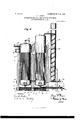
- Figure 1 represents a front view of my improved steain-generating apparatus.
- Fig. 2 is a top plan view of the same.
- Fig. 3 is a vertical transverse section on the line 3 3, Fig. 2, showing the boilers and the pipes con nected thereto in elevation.
- Fig. 4 is a vertical longitudinal section on the line4 4, Fig. 2, showing the boilers and the pipes connected thereto in elevation; and
- Fig. 5 is a detach ed enlarged vertical cross-section view of the steam-drum.
- the tubes constituting the boiler 1 are greater in uimber and smaller in size than the tubes of only in its upper portion, the lower portion of the same being enlarged, as shown in Fig. 3, into the furnaces 11 and 12.
- the walls of these furnaces and retorts are built up of ordinary building-bricks or other suitable constructive material, the inner surfaces of the walls being lined or covered with a veneer of or refracted thereby.
- fire-brick I have devised and employed the peculiar form of fire-brick shown, by which is obtained an interior surface for these retort and furnace walls which will-present a succession of angularly-disposed surfaces and successive horizontally-extending sharp lines.
- the object of this feature is to increase the wall area traversed by the heat and gases of combustion, whereby the same may be readily absorbed by and retained in and radiated 7 Moreover, these projecting portions of the fire-brick interior will readily become heated intensely and will by the latent heat contained therein contribute to the complete combustion and burning of the effluvia and gases emanating from the furnace-fires.
- a further purpose is that these successively-disposed ridges will present such obstacle to the heat-currents that the same will be directed away from the walls and inwardly through and about the tubes. For the reason that the heat should be kept circulating uniformly as possible in and among the tubes continuously throughout their ex tent these retorts and the heating devices described are provided.
- the upper part of the retorts 7 and 8 are closed, as shown in Fig. 4, and brought to a termination continuously about the water drum 5 and the steam-drum 6.
- the fire-brick lining is dispensed with, whereby the continuous cylindrical chambers 13 and 14 are pro vided, adapted to retain normally a portionof the heat of the retorts.
- Inthe furnace and retort walls are provided at suitable locations proper apertures 21*, as shown in Fig. 1, affording access to the boilers for the purpose of inserting and operating means for cleaning and for purposes of the examination of the boilers. It will be understood that these openings 21 are normally closed by such suitable means as may beconveniently employed.
- the furnaces 11 and 1 asplainly shown in Fig. 3, are provided with the suitable gratings 22, supported by proper fastenings in thewalls, and underneath the gratings are the suitable draft-chambers 23.
- Theobject of the longitudinal walls 24 is to provide separators by which the contact with the boilers or the drums or any portion thereof of unheated atmosphere is prevented.
- aprons 25 and 26 Extending transversely and suitably secured to the furnacewalls and 10 are the aprons 25 and 26, made of suitable fireproof material, supported on suitable girders properly secured in the walls.
- the aprons 25 and 26 In the furnace 11 is provided the upwardly-extending dash 27, and in the furnace 12 is provided the vertically-disposed continuation 28 of the wall 24.
- Formed integral with the wall 28 anddisposed diagonally is the dash 29, and formed integral with the apron 26 is the depending dash 30'.
- the walls 10, forming the rear part of the furnaces, are continuous.
- the fire-doors 31 and the ash-pit doors 32 Provided in the front wall of the furnaces.
- the' verticallydisposed angle-bars 33 secured at their bottoms to proper foundation and bound together at their tops longitudinally and transversely by the tie-rods 34, are provided.
- the vertically-extending passage 35 In the enlarged portion of the wall of the retort 8, adjacent and superincumbent the furnace 1. 2', is provided the vertically-extending passage 35, adapted to conduct a portion of the freshly-generated heat of furnace 12 directly into the chamber 14.
- the pipe 37 Provided at the mud-drums 3 and 4 and communicatingly connecting the same at a point well above the bottoms of these drums to permit the settling in drum 3 of such sediment as may be carried by the water, is the pipe 37, through which the Water may freelypass from boiler 1 toboiler 2.
- This pipe is provided with the suitable regulator and check valve 38, which is manipulated by the stem extended outside the apparatus and provided with the wheel 38, as shown in Fig.
- valve 2 the purpose of said valve being to afford means for the regulation and'check of the flow ofthe water from boiler 1 into boiler-2, and the prevention, under the steam-pressure Within the boiler 2, of the backfiow of the water from the boiler 2 to boiler 1.
- the-boiler-l, drums 3 and 5, and pipe36, as Well as the drum 4 and tubes 2 are kept completely filled with water under pump pressure and suitable system. of check and regulator valves well known and universally used in steam-boilers,
- blow-off pipes 39 and 40 are rovided at the bottoms of the boilers 1 an 2, res ectively, for the discharge, when desired, 0 the contents of the boilers.
- the shell 41 Within the drum 6 is provided the shell 41, the body of the same being 0 lindrical and adapted to reside concentrica ly within the drum.
- the upper ortion 41 of this shell is slightly flaring an the lower portion 41 is bent obliquely outwardly, thence flanged vertically and rigidly secured to the walls of the drum, the lower line of this shell marking the line which the water in the boiler is intended to assume and retain in the process of steam-generation.
- the chamber 46 Formed by the shell 41 is the chamber 46, which constitutes a suitable rece tacle for the generated steam and wherein t e same is superheated before its final escape at such time and in such quantities as may be desired through the outlet-pipe 47.
- a steam-generating apparatus the combination with a rimary and secondary boiler positioned slightly apart and connected to each other by a conduit for circulation and suitable means for supplying with and reventing the escape of water from the said Boilers, retorts inclosing said boilers, the retort of the secondary boiler being broadened into furnaces on the opposite sides of said secondary boiler, said furnace having means whereby the fire therein is directed downwardly and upwardly from said furnaces into contact with the secondary boiler, the secondary upwardly-extending passage 35 fromthe fire-box adjacent the secondary boiler whereby the heat is directed against the drum 6 thereof, a dividing-wall between said boilers having an aperture therein near the upper portion of said boilers, a dischargechamber in the lower portion adjacent to and communicating with the retort surrounding the rimary boiler and leading to the smokestac 2.
- a steam-generating apparatus the combination with a primary and secondary boiler of the water-tube type, positioned slightly apart and vertically disposed and communicatingly connected to each other, retorts inclosing said boilers, the retort of the secondary boiler being broadened into furnaces on the opposite sides of said secondary boiler, said furnaces having means wherein the fire therein is directed downwardly and upwardly from said furnaces into contact with the secondary boiler, the secondary upwardly-extending passage 35 from the firebox adjacent the secondary boiler whereby the heat is directed against the drum 6 thereof, a dividing-wall between said boilers having an aperture therein near the .upperportion of the boilers, a'discharge-chamber in the lower portion ofthe retort surrounding the primary boiler havingra passage leading therefrom and communicating with the smoke-stack, a pipe arranged within the smoke-stack through which said pipe the feed-Water for the boilers is projected upyvardly and fed into the upper portion of the primary boiler, a pipe connecting the primary boiler to the
- a steam-generating apparatus the combination with a water-tube boiler vertically disposed within a suitable heating-furnace and having a drum at its upper portion and suitable secondary passage from the heating-furnace for directing and discharging a continuous and uniformly high degree of heat against the exterior of the same, of a cylindrical shell of smaller diameter than the drum having its upper ed e flaring and its lower portion bent oblique y outwardly and with vertically-disposed continuous flange secured to said drum upon a line substantially intermediate the bottom and top of said In testimony whereof I have hereunto I signed my name to this specification in the presence of two subscribing witnesses.
Landscapes
- Engineering & Computer Science (AREA)
- Chemical & Material Sciences (AREA)
- Combustion & Propulsion (AREA)
- Physics & Mathematics (AREA)
- Thermal Sciences (AREA)
- Mechanical Engineering (AREA)
- General Engineering & Computer Science (AREA)
- Control Of Steam Boilers And Waste-Gas Boilers (AREA)
Description
N0.,831,768. PATENTED SEPT. 25, 1906- I. H. BUYER.
(OM/i. wow had/ W 25% Q. .cg 2:
A TTORNE Y PATENTED SEPTA 25, 1906.
I. H. BOYER. APPARATUS FOR THE GENERATION 0F STEAM.
APPLICATION FILED DEO.11,1905.
INVENTOR AnpRNEy I WITNESSES: o @M. vmmb.
nu. warm; plrnu cm, Inn/mam", a. c.
No. 831,768. PATENTED SEPT. 25, 1906.
I. H. BOYER.
APPARATUS FOR THE GENERATION 0P STEAM.
APPLICATION FILED DEO.11,1905.
' 4 SKEETBSHEET 3.
No. 831,768. PATENTED SEPT. 251906. I. H. BQYER. APPARATUS FOR THE GENERATION F STEAM.
APPLICATION FILED DBO. 11,1906.
4 SHEETS-SHEET 4.
5 I9 47 I I 5 E o "0 /3 4 is 39 v 21 2a l0 2/ i wmvsssss: 7 3 2O 9 1 OLA/AA. Wm 37 w /"fl %n Q? v ATTORNEY Tn: nouns nzrrxs cu. \nsmnarou. a. c.
ISAAC I-I. BOYER, OF MUNCIE, INDIANA.
APPARATUS FOR THE GENERATION OF STEAM.
Specification of Letters Patent.
Patented Sept. 25, 1906.
Application fil d December 11, 1905. Serial No. 291,324.
To all whmn it may concern.-
Be it known that I, ISAAC H. 130mm, a citizen of the United States, residing at Muncie, in the county of Delaware and State of Indiana, have invented a new and useful Apparatus for the Generation of Steam, of which the following is a specification.
My invention has reference to improvements in apparatus for the generation of steam wherein are used the commonly known water-tube boilers.
In the adaptation of the water-tube boiler for the generation and superheating and supplying of steam for manufacturing purposes as now practiced the faults in the construction and arrangement of the boilers and superheating devices and the furnaces from which the heat is obtained are that the inte rior of the furnace is of such form and arrangement and the boilers are so formed and placed with reference thereto and the mode of the circulation of the water is such that the fire and heat in its initial and maximum de gree of temperature as generated in the furnace for the purpose of producing the steam is directed against the boiler or boilers at the portions wherein is injected and retained the water having its initial degree of temperature, thereby causing unnecessarily a substantial portion of this initial heat to be absorbed. By reason of the excessive extent of the wall area of furnaces and the presence of air-currents of unheated and fluctuating degrees of temperature and the lack of means for the circulation of the heat with especial reference to the circulation of the water to be heated, which faults prevail in steam-generating apparatus now in use, a further portion of the initial and efficient part of the heat generated is by absorption unnecessarily consumed and wasted, the result being the we treme difficulty in maintaining an equable pressure and supply of steam except by the most skilful firing and handling and the consum ption of large quantities of fuel.
My invention has for its purpose to provide an apparatus for the generation of steam consisting of water-tube boilers and furnaces so arranged and constructed that facility is afforded whereby with a predetermined course of circulation of the water in and through the boilers the degree of temperature of the water as it commences its circulation may be increased by the action of the waning or spent portion of the heat and gases generated in the firing portion of the furnaces, and the heat from the furnace superheated and maintained in its normal superheated condition. These and other objects are accomplished by the construction described in the following specification and illustrated in the accompanying drawings.
Similar figures of reference refer to corresponding parts throughout the several views, in which Figure 1 represents a front view of my improved steain-generating apparatus. Fig. 2 is a top plan view of the same. Fig. 3 is a vertical transverse section on the line 3 3, Fig. 2, showing the boilers and the pipes con nected thereto in elevation. Fig. 4 is a vertical longitudinal section on the line4 4, Fig. 2, showing the boilers and the pipes connected thereto in elevation; and Fig. 5 is a detach ed enlarged vertical cross-section view of the steam-drum.
1 and 2 designate two ordinary steam-boilers of the well-known water-tube type, vertically disposed, each provided at its lower portion with the mud-drums 3 and L, respectively, and at their upper portions with the water-drum 5 and the steam-drum 6. The tubes constituting the boiler 1 are greater in uimber and smaller in size than the tubes of only in its upper portion, the lower portion of the same being enlarged, as shown in Fig. 3, into the furnaces 11 and 12. The walls of these furnaces and retorts are built up of ordinary building-bricks or other suitable constructive material, the inner surfaces of the walls being lined or covered with a veneer of or refracted thereby.
fire-brick. I have devised and employed the peculiar form of fire-brick shown, by which is obtained an interior surface for these retort and furnace walls which will-present a succession of angularly-disposed surfaces and successive horizontally-extending sharp lines. The object of this feature is to increase the wall area traversed by the heat and gases of combustion, whereby the same may be readily absorbed by and retained in and radiated 7 Moreover, these projecting portions of the fire-brick interior will readily become heated intensely and will by the latent heat contained therein contribute to the complete combustion and burning of the effluvia and gases emanating from the furnace-fires. A further purpose is that these successively-disposed ridges will present such obstacle to the heat-currents that the same will be directed away from the walls and inwardly through and about the tubes. For the reason that the heat should be kept circulating uniformly as possible in and among the tubes continuously throughout their ex tent these retorts and the heating devices described are provided.
The upper part of the retorts 7 and 8 are closed, as shown in Fig. 4, and brought to a termination continuously about the water drum 5 and the steam-drum 6. In these upper portions of the retorts the fire-brick lining is dispensed with, whereby the continuous cylindrical chambers 13 and 14 are pro vided, adapted to retain normally a portionof the heat of the retorts. Provided in the wall separating the boilers is the passage 15, V
and in the foundation-wall 9 is the passage 16, these passages affording communication between the retorts 8 and 7 and between the chamber 17 of the retort 7 and the stackchamber 18. This stack-chamber is inclosed by suitable wall extending upwardly sufficiently to provide a receptacle for soot and ashes and for a base upon which is supported and retained the smoke-stack 19. Beneath theboilers are the-air-spaces 20, the filling 21,
- drums of the-boilers.
Inthe furnace and retort walls are provided at suitable locations proper apertures 21*, as shown in Fig. 1, affording access to the boilers for the purpose of inserting and operating means for cleaning and for purposes of the examination of the boilers. It will be understood that these openings 21 are normally closed by such suitable means as may beconveniently employed. The furnaces 11 and 1 2, asplainly shown in Fig. 3, are provided with the suitable gratings 22, supported by proper fastenings in thewalls, and underneath the gratings are the suitable draft-chambers 23. Theobject of the longitudinal walls 24 is to provide separators by which the contact with the boilers or the drums or any portion thereof of unheated atmosphere is prevented. Extending transversely and suitably secured to the furnacewalls and 10 are the aprons 25 and 26, made of suitable fireproof material, supported on suitable girders properly secured in the walls. In the furnace 11 is provided the upwardly-extending dash 27, and in the furnace 12 is provided the vertically-disposed continuation 28 of the wall 24. Formed integral with the wall 28 anddisposed diagonally is the dash 29, and formed integral with the apron 26 is the depending dash 30'. The walls 10, forming the rear part of the furnaces, are continuous. Provided in the front wall of the furnaces are the fire-doors 31 and the ash-pit doors 32. For bracing and stiffening the furnace structure the' verticallydisposed angle-bars 33, secured at their bottoms to proper foundation and bound together at their tops longitudinally and transversely by the tie-rods 34, are provided. In the enlarged portion of the wall of the retort 8, adjacent and superincumbent the furnace 1. 2', is provided the vertically-extending passage 35, adapted to conduct a portion of the freshly-generated heat of furnace 12 directly into the chamber 14.
36 designates the inlet-pipe through which passes the water intended for use in the boilers. The entry for this pipe, which is provided with the suitable regulator and check valve 36 is provided at the chamber 18, whence it extends upwardly within the smoke-stack to a oint above the height of the water-drum of the boiler 1, into which drum 5 it is secured at its top. This ipe is shown as traversing the extent within the smoke-stack in aspiral. The object of this arrangement is to afford as much area as possible for the water to travel through the heat contained in the, stack and before reaching the boiler. Provided at the mud- drums 3 and 4 and communicatingly connecting the same at a point well above the bottoms of these drums to permit the settling in drum 3 of such sediment as may be carried by the water, is the pipe 37, through which the Water may freelypass from boiler 1 toboiler 2. This pipe is provided with the suitable regulator and check valve 38, which is manipulated by the stem extended outside the apparatus and provided with the wheel 38, as shown in Fig.
2, the purpose of said valve being to afford means for the regulation and'check of the flow ofthe water from boiler 1 into boiler-2, and the prevention, under the steam-pressure Within the boiler 2, of the backfiow of the water from the boiler 2 to boiler 1. It will be understood that the-boiler-l, drums 3 and 5, and pipe36, as Well as the drum 4 and tubes 2, are kept completely filled with water under pump pressure and suitable system. of check and regulator valves well known and universally used in steam-boilers,
so that under the high degree of furnace temerature maintained about the tubes 2 the eight of the water-level therein may by the manipulation of the suitable regulator and check valves be controlled, and thus may the evaporating-space be confined in the drum 6 to such extent as may be desired. The blow-off pipes 39 and 40 are rovided at the bottoms of the boilers 1 an 2, res ectively, for the discharge, when desired, 0 the contents of the boilers.
Within the drum 6 is provided the shell 41, the body of the same being 0 lindrical and adapted to reside concentrica ly within the drum. The upper ortion 41 of this shell is slightly flaring an the lower portion 41 is bent obliquely outwardly, thence flanged vertically and rigidly secured to the walls of the drum, the lower line of this shell marking the line which the water in the boiler is intended to assume and retain in the process of steam-generation.
42 designates an ordinary water-gage, and 43 represents a safety-valve suitably secured to the crown 44 of the drum 6.
44 designates a suitable discharge-pipe through which may be discharged such refuse as may accumulate within the chamber 46.
Formed by the shell 41 is the chamber 46, which constitutes a suitable rece tacle for the generated steam and wherein t e same is superheated before its final escape at such time and in such quantities as may be desired through the outlet-pipe 47.
In the operation of my invention water is injected into the inlet-pipe 36, and the boilers are filled. Fire is then started in the furnaces 11 and 12. By the peculiar formation of the interior of the furnaces the fire and flame and the heated gases of combustion in their escape therefrom are impelled downwardly by the apron 25 and the dash 27 in and through the spaces between the boilertubes and by the apron 26 and the dashes 2S and 29 caused to ascend, a certain portion of the heat from furnace 12 ascending through passage 35 to and keeping a continuous heat of high degree in the chamber 14, whereby a continuous and intense heat is maintained in contact with that portion of the boiler wherein the evaporation of the water takes place. By the means described of discharging the heat from the furnaces into the retort 8 such circulation of the same is obtained that the maximum and highest degree of heat obtained and generated by the fire is available for this boiler, From the retort 8 the heat passes through the aperture 15 into the retort 7, thence downwardly it circulates in and about the tubes around and under the drum 3, thence through the opening 16 into the chamber 18, thence upwardly escaping through the stack 19. In the boiler 1 the tubes are of comparatively greater number and smaller in size than in the boiler 2, the purpose being to afford a more extensive area for the contact of the heat of the retort 7 with the same by reason of the lower temperature of the incoming water. It will be seen that by this arrangement of the boilers and the construction and ada tation of the furnaces and retorts with re erence to the same the spent portion of the heat from the furnaces passing through the chamber 18 and the smoke-stack 1 is utilized in primarily heating the incoming feed-water. As the water increases in temperature it reaches those portions of the retorts wherein the more intense heat exists, thus absorbing a minimum amount of the said heat and en abling the heat to stimulate and superheat the water and more easily maintain the high temperature of the same, and, further, the heat afl'orded for the superheating of the steam and the steam retained to be superheated both being at their highest temperature the maximum degree of superheating is not only accomplished, but is easily maintained in the highest degree.
What I claim as my invention, and desire to secure by Letters Patent of the United States, is
1. In a steam-generating apparatus, the combination with a rimary and secondary boiler positioned slightly apart and connected to each other by a conduit for circulation and suitable means for supplying with and reventing the escape of water from the said Boilers, retorts inclosing said boilers, the retort of the secondary boiler being broadened into furnaces on the opposite sides of said secondary boiler, said furnace having means whereby the fire therein is directed downwardly and upwardly from said furnaces into contact with the secondary boiler, the secondary upwardly-extending passage 35 fromthe fire-box adjacent the secondary boiler whereby the heat is directed against the drum 6 thereof, a dividing-wall between said boilers having an aperture therein near the upper portion of said boilers, a dischargechamber in the lower portion adjacent to and communicating with the retort surrounding the rimary boiler and leading to the smokestac 2. In a steam-generating apparatus, the combination with a primary and secondary boiler of the water-tube type, positioned slightly apart and vertically disposed and communicatingly connected to each other, retorts inclosing said boilers, the retort of the secondary boiler being broadened into furnaces on the opposite sides of said secondary boiler, said furnaces having means wherein the fire therein is directed downwardly and upwardly from said furnaces into contact with the secondary boiler, the secondary upwardly-extending passage 35 from the firebox adjacent the secondary boiler whereby the heat is directed against the drum 6 thereof, a dividing-wall between said boilers having an aperture therein near the .upperportion of the boilers, a'discharge-chamber in the lower portion ofthe retort surrounding the primary boiler havingra passage leading therefrom and communicating with the smoke-stack, a pipe arranged within the smoke-stack through which said pipe the feed-Water for the boilers is projected upyvardly and fed into the upper portion of the primary boiler, a pipe connecting the primary boiler to the secondary boiler at a point above and apart from the bottom part of said boilers and having a regulator and check valve therein, means in the upper drum of the secondary boiler whereby the generated steam may be retained in a receptacle apart from the wet steam of evaporation, suitable outlet from said drum affording egress of the steam generated, from the superheating-receptacle thereof.
3. In a steam-generating apparatus, the combination with a water-tube boiler vertically disposed within a suitable heating-furnace and having a drum at its upper portion and suitable secondary passage from the heating-furnace for directing and discharging a continuous and uniformly high degree of heat against the exterior of the same, of a cylindrical shell of smaller diameter than the drum having its upper ed e flaring and its lower portion bent oblique y outwardly and with vertically-disposed continuous flange secured to said drum upon a line substantially intermediate the bottom and top of said In testimony whereof I have hereunto I signed my name to this specification in the presence of two subscribing witnesses.
ISAAC H. BOYER.
Witnesses GEO. R. JoNEs, SAMUEL M. SNODGRASS.
at a point below the
Priority Applications (1)
| Application Number | Priority Date | Filing Date | Title |
|---|---|---|---|
| US29132405A US831768A (en) | 1905-12-11 | 1905-12-11 | Apparatus for the generation of steam. |
Applications Claiming Priority (1)
| Application Number | Priority Date | Filing Date | Title |
|---|---|---|---|
| US29132405A US831768A (en) | 1905-12-11 | 1905-12-11 | Apparatus for the generation of steam. |
Publications (1)
| Publication Number | Publication Date |
|---|---|
| US831768A true US831768A (en) | 1906-09-25 |
Family
ID=2900243
Family Applications (1)
| Application Number | Title | Priority Date | Filing Date |
|---|---|---|---|
| US29132405A Expired - Lifetime US831768A (en) | 1905-12-11 | 1905-12-11 | Apparatus for the generation of steam. |
Country Status (1)
| Country | Link |
|---|---|
| US (1) | US831768A (en) |
-
1905
- 1905-12-11 US US29132405A patent/US831768A/en not_active Expired - Lifetime
Similar Documents
| Publication | Publication Date | Title |
|---|---|---|
| US831768A (en) | Apparatus for the generation of steam. | |
| US152064A (en) | Improvement in steam-boilers | |
| US289989A (en) | culver | |
| US355178A (en) | William a | |
| US482384A (en) | Bowie and elijah j | |
| US1577549A (en) | Boiler | |
| US414297A (en) | Steam-generator | |
| US474385A (en) | Steam-generator | |
| US375580A (en) | Steam-generator | |
| US590471A (en) | baker | |
| US404740A (en) | Steam-generator | |
| US553700A (en) | Marine boiler | |
| US335680A (en) | Theodoee e | |
| US582381A (en) | Water-tube boiler | |
| US474386A (en) | Porcupine steam-generator | |
| USRE13210E (en) | Fire-box for locomotive-boilers | |
| US778767A (en) | Steam-generator. | |
| US211190A (en) | Improvement in steam-generators | |
| US434226A (en) | Island | |
| US544619A (en) | hazlett | |
| US400462A (en) | Brothers | |
| US234872A (en) | Steam-generator | |
| US458818A (en) | baied | |
| US416558A (en) | Steam-boiler | |
| US795406A (en) | Return-flue boiler. |