US8220942B2 - Lighting device for display device, display device, and television receiver apparatus - Google Patents
Lighting device for display device, display device, and television receiver apparatus Download PDFInfo
- Publication number
- US8220942B2 US8220942B2 US12/594,920 US59492007A US8220942B2 US 8220942 B2 US8220942 B2 US 8220942B2 US 59492007 A US59492007 A US 59492007A US 8220942 B2 US8220942 B2 US 8220942B2
- Authority
- US
- United States
- Prior art keywords
- optical member
- support portion
- display device
- linear support
- light source
- Prior art date
- Legal status (The legal status is an assumption and is not a legal conclusion. Google has not performed a legal analysis and makes no representation as to the accuracy of the status listed.)
- Expired - Fee Related, expires
Links
Images


Classifications
-
- G—PHYSICS
- G02—OPTICS
- G02F—OPTICAL DEVICES OR ARRANGEMENTS FOR THE CONTROL OF LIGHT BY MODIFICATION OF THE OPTICAL PROPERTIES OF THE MEDIA OF THE ELEMENTS INVOLVED THEREIN; NON-LINEAR OPTICS; FREQUENCY-CHANGING OF LIGHT; OPTICAL LOGIC ELEMENTS; OPTICAL ANALOGUE/DIGITAL CONVERTERS
- G02F1/00—Devices or arrangements for the control of the intensity, colour, phase, polarisation or direction of light arriving from an independent light source, e.g. switching, gating or modulating; Non-linear optics
- G02F1/01—Devices or arrangements for the control of the intensity, colour, phase, polarisation or direction of light arriving from an independent light source, e.g. switching, gating or modulating; Non-linear optics for the control of the intensity, phase, polarisation or colour
- G02F1/13—Devices or arrangements for the control of the intensity, colour, phase, polarisation or direction of light arriving from an independent light source, e.g. switching, gating or modulating; Non-linear optics for the control of the intensity, phase, polarisation or colour based on liquid crystals, e.g. single liquid crystal display cells
- G02F1/133—Constructional arrangements; Operation of liquid crystal cells; Circuit arrangements
- G02F1/1333—Constructional arrangements; Manufacturing methods
- G02F1/1335—Structural association of cells with optical devices, e.g. polarisers or reflectors
- G02F1/1336—Illuminating devices
- G02F1/133602—Direct backlight
- G02F1/133608—Direct backlight including particular frames or supporting means
-
- G—PHYSICS
- G02—OPTICS
- G02F—OPTICAL DEVICES OR ARRANGEMENTS FOR THE CONTROL OF LIGHT BY MODIFICATION OF THE OPTICAL PROPERTIES OF THE MEDIA OF THE ELEMENTS INVOLVED THEREIN; NON-LINEAR OPTICS; FREQUENCY-CHANGING OF LIGHT; OPTICAL LOGIC ELEMENTS; OPTICAL ANALOGUE/DIGITAL CONVERTERS
- G02F1/00—Devices or arrangements for the control of the intensity, colour, phase, polarisation or direction of light arriving from an independent light source, e.g. switching, gating or modulating; Non-linear optics
- G02F1/01—Devices or arrangements for the control of the intensity, colour, phase, polarisation or direction of light arriving from an independent light source, e.g. switching, gating or modulating; Non-linear optics for the control of the intensity, phase, polarisation or colour
- G02F1/13—Devices or arrangements for the control of the intensity, colour, phase, polarisation or direction of light arriving from an independent light source, e.g. switching, gating or modulating; Non-linear optics for the control of the intensity, phase, polarisation or colour based on liquid crystals, e.g. single liquid crystal display cells
- G02F1/133—Constructional arrangements; Operation of liquid crystal cells; Circuit arrangements
- G02F1/1333—Constructional arrangements; Manufacturing methods
- G02F1/1335—Structural association of cells with optical devices, e.g. polarisers or reflectors
- G02F1/1336—Illuminating devices
- G02F1/133602—Direct backlight
- G02F1/133604—Direct backlight with lamps
-
- G—PHYSICS
- G02—OPTICS
- G02F—OPTICAL DEVICES OR ARRANGEMENTS FOR THE CONTROL OF LIGHT BY MODIFICATION OF THE OPTICAL PROPERTIES OF THE MEDIA OF THE ELEMENTS INVOLVED THEREIN; NON-LINEAR OPTICS; FREQUENCY-CHANGING OF LIGHT; OPTICAL LOGIC ELEMENTS; OPTICAL ANALOGUE/DIGITAL CONVERTERS
- G02F2201/00—Constructional arrangements not provided for in groups G02F1/00 - G02F7/00
- G02F2201/54—Arrangements for reducing warping-twist
Definitions
- the present invention relates to a lighting device for a display device, a display device, and a television receiver apparatus.
- a liquid crystal display device includes a liquid crystal panel, and a backlight provided on a back surface side of the liquid crystal panel.
- the backlight includes a chassis housing a light source such as a cold cathode tube and having an opening surface on a light emitting side, and an optical member provided in an opening portion of the chassis and having a function of converting a light emitted from the light source into a uniform planar light.
- the optical member includes a diffuser plate containing a plurality of diffusing particles dispersed in a transparent base material having a predetermined thickness, and an outer peripheral end portion thereof is received and supported by a catch in the chassis. Meanwhile, a more inner portion than the outer peripheral end portion of the diffuser plate is supported by a support component mounted to the chassis.
- This support component includes a support pin protruding toward a diffuser plate, and a tip portion of the support pin abuts at a point against a more inner portion than an outer peripheral end portion of the diffuser plate to support the diffuser plate.
- a plurality of support pins are arranged so as to support the diffuser plate in different positions in a plane direction.
- This support component includes a linear support portion having a top extending in one direction, and linearly supports a diffuser plate.
- the above described diffuser plate is sometimes warped into an arc shape toward a light source as the light source is lit and a temperature in the chassis is increased.
- the support pins described in Patent Document 1 all have the same height, the diffuser plate may be bent into a corrugated shape toward the light source with a support position by each support pin as a fulcrum. Then, the corrugated bent portion may significantly reduce display quality of a liquid crystal display device.
- the support portion described in Patent Document 2 linearly supports the diffuser plate, and the diffuser plate is hard to be bent as described above in an extending direction of the support portion.
- the support portion has a fixed height over the entire length, the diffuser plate to be warped and deformed toward the light source may press the support portion to cause a problem such as a groan.
- the present invention is achieved in view of the above described circumstances and has an object to properly support an optical member.
- the present invention includes: a chassis housing a light source that applies a light to a display panel that displays an image; a planar optical member provided on an emission side of the light emitted from the light source; and a support component that is mounted to the chassis and can support the optical member from the side of the light source, wherein the support component includes a lower support portion corresponding to a middle side of the optical member and a higher support portion corresponding to an end side of the optical member, and supports the optical member perpendicularly to a plane direction of the optical member in a fixed position at least in the lower support portion.
- the optical member is warped and deformed toward the light source as the light source is lit or the like, the optical member is shaped to become lower from the end side toward the middle side. At this time, the optical member can be supported in a position matching the warped shape by the lower support portion and the higher support portion of the support component. Thus, the optical member can be supported in a state where the optical member can be warped and deformed and the optical member is hard to be bent. Also, the optical member is supported in the fixed position in the lower support portion, thereby allowing excessive warping deformation of the optical member to be controlled.
- FIG. 1 is a schematic exploded view of a television receiver apparatus according to Embodiment 1 of the present invention.
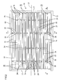
- FIG. 2 is a plan view of a backlight
- FIG. 3 is a sectional view taken along the line A-A in FIG. 2 ;
- FIG. 4 is a sectional view taken along the line B-B in FIG. 2 ;
- FIG. 5 is a sectional view taken along the line A-A in FIG. 2 of a diffuser plate being warped and deformed;
- FIG. 6 is a sectional view taken along the line B-B in FIG. 2 of the diffuser plate being warped and deformed;
- FIG. 8 is a sectional view taken along the line C-C in FIG. 8 ;
- FIG. 9 is a side sectional view of a backlight according to Embodiment 3 of the present invention.
- FIG. 10 is a partial plan view of a backlight according to Embodiment 4 of the present invention.
- FIG. 11 is a side sectional view of the backlight
- FIG. 12 is a side view of split components of a linear support portion according to Embodiment 5 of the present invention.
- FIG. 13 is a side view of the split components being assembled to each other
- FIG. 14 is a cross sectional view of connection between the split components
- FIG. 15 is a side view of split components of a linear support portion according to Embodiment 6 of the present invention.
- FIG. 16 is a side view of the split components being assembled to each other
- FIG. 17 is a cross sectional view of connection between the split components
- FIG. 18 is a partial side view of a diffuser plate according to another embodiment (12).
- FIG. 19 is a partial side view of a diffuser plate according to a further embodiment (13).
- FIG. 20 is a partial plan view of a backlight according to a further embodiment (15).
- Embodiment 1 of the present invention will be described with reference to FIGS. 1 to 6 .
- a liquid crystal display device D is exemplified as a display device.
- the liquid crystal display device D has a generally horizontally oriented rectangular shape, and includes, as shown in FIG. 3 , a liquid crystal panel 11 as a display panel and a backlight 10 as an external light source (illumination device) of the liquid crystal panel 11 assembled to each other and held by a bezel 12 placed on a front side.
- the liquid crystal panel 11 is placed on a front surface side of the backlight 10 , and the backlight 10 illuminates the liquid crystal panel 11 from a back surface side.
- the liquid crystal display device D can be applied to a television receiver apparatus TV.
- the television receiver apparatus TV includes, as shown in FIG. 1 , the liquid crystal display device D, front and back cabinets Ca and Cb that sandwich and house the liquid crystal display device D, a power supply P, a tuner T, and a stand S.
- the liquid crystal panel 11 has a known structure in which a liquid crystal that is a substance having varying optical properties with application of a voltage is sealed in a gap between a transparent TFT substrate and a transparent CF substrate.
- a TFT Thin Film Transistor
- three color filters of red (R), green (G) and blue (B) are arranged in a matrix on the CF substrate.
- a polarizing plate is attached to the side opposite to the liquid crystal of each substrate.
- the backlight 10 is of a so-called direct type, and includes a chassis 13 having an opening surface on a front side (an upper side in FIGS. 3 and 4 , a front surface side) that is a light emission side, a reflective sheet 14 laid in the chassis 13 , a plurality of cold cathode tubes 15 housed in the chassis 13 , an optical member 16 provided in an opening portion of the chassis 13 , that is, on the emission side of lights emitted from the cold cathode tubes 15 , positioning members (a lamp holder 17 , a holder 18 , and a frame 19 described later) that can position the optical member 16 , and a support component 20 that can support the cold cathode tubes 15 and the optical member 16 .
- a chassis 13 having an opening surface on a front side (an upper side in FIGS. 3 and 4 , a front surface side) that is a light emission side, a reflective sheet 14 laid in the chassis 13 , a plurality of cold cathode tubes 15 housed in the
- the chassis 13 is made of metal, and formed into a rectangular on plan view and shallow substantially box shape having an opening surface on a front side as shown in FIG. 2 .
- the reflective sheet 14 is made of synthetic resin, has a surface with white base color such as white with high reflectivity, and is laid on an inner surface of the chassis 13 so as to substantially cover the entire inner surface. The reflective sheet 14 can guide the light emitted from each cold cathode tube 15 to the opening portion of the chassis 13 .
- the cold cathode tube 15 is a kind of elongated linear light source extending in one direction along a bottom plate 13 a of the chassis 13 or the plane direction of the optical member 16 , and is mounted in the chassis 13 with an axial direction thereof matching a long side direction of the chassis 13 .
- the plurality of cold cathode tubes 15 are arranged axially substantially in parallel with predetermined spaces therebetween. More specifically describing the space (pitch, distance) between adjacent cold cathode tubes 15 , a space between cold cathode tubes 15 placed in the middle in a short side direction of the chassis 13 or the optical member 16 is smallest, and the space progressively increases therefrom toward end sides.
- a density of arrangement of the cold cathode tubes 15 in the chassis 13 is higher on the middle side of a screen, and becomes progressively lower toward end sides of the screen.
- the cold cathode tubes 15 are arranged symmetrically with respect to an axis of symmetry L 1 (a dash-double-dot line in FIG. 2 ) in a middle position in the short side direction of the chassis 13 .
- the cold cathode tube 15 is configured so that mercury or the like is sealed in an elongated glass tube having a circular section, an inner wall surface of the tube is coated with a fluorescent material, and electrodes are sealed in opposite end portions.
- a rubber holder 21 mounted to the chassis 13 is fitted to a non-light-emitting portion at each end of the cold cathode tube 15 .
- the optical member 16 has a rectangular shape on plan view like the chassis 13 and the liquid crystal panel 11 as shown in FIGS. 3 and 4 , is made of translucent synthetic resin, mounted to the opening portion of the chassis 13 and interposed between the group of cold cathode tubes 15 and the liquid crystal panel 11 .
- the optical member 16 includes a diffuser plate 16 A, a diffusion sheet 16 B, a lens sheet 16 C, and a luminance increasing sheet 16 D laminated in order from a back side (a lower side in FIGS. 3 and 4 , a back surface side), and has a function of converting the light emitted from each cold cathode tube 15 as the linear light source into a uniform planar light or the like.
- the diffuser plate 16 A placed on the backmost side has a sufficiently larger thickness than other sheets 16 B to 16 D and has relatively high rigidity.
- the diffuser plate 16 A contains a plurality of diffusing particles dispersed in a transparent base material having a predetermined thickness, and is thus formed to be generally translucent.
- the diffuser plate 16 A is sometimes warped and deformed by an influence of ambient temperature environment or the like.
- the sheets 16 B to 16 D are also deformed following the warped and deformed diffuser plate 16 A. If the optical member 16 is warped and deformed toward the liquid crystal panel 11 at this time, the optical member 16 presses the middle portion of the liquid crystal panel 11 to cause poor display.
- the diffuser plate 16 A is subjected to so-called previous warping so as to have a warping habit to be warped toward the cold cathode tube 15 .
- the previous warping is performed by heating only a surface on the front side (on the side opposite to the cold cathode tube 15 ) of the base material while the base material passes between upper and lower rollers in a process of producing the diffuser plate 16 A.
- the diffuser plate 16 A has a warping habit such that the heated-side surface is deformed to be recessed (the middle side is retracted from the outer peripheral end portion 16 b toward the back side (toward the cold cathode tube 15 ).
- the positioning member includes the lamp holder 17 and the holder 18 that constitute a frame-shaped catch member that receives the outer peripheral end portion 16 b of the optical member 16 on the back side, and the frame 19 that constitutes a frame-shaped presser member that presses the outer peripheral end portion 16 b of the optical member 16 from the front side.
- the lamp holder 17 is made of synthetic resin having a surface with white base color such as white, and as shown in FIGS. 2 and 3 , a pair of lamp holders 17 are mounted to opposite end positions in the long side direction of the chassis 13 and extend in the short side direction of the chassis 13 .
- the lamp holder 17 has a substantially box shape with an opening back surface side so as to collectively cover the rubber holders 21 mounted to the cold cathode tubes 15 from the front side.
- a catch 22 that can receive the optical member 16 is formed to be recessed with a step in an inner peripheral end portion on a front side surface of the lamp holder 17 .
- the holder 18 is made of synthetic resin having a surface with white base color such as white, and as shown in FIGS. 2 and 4 , a pair of holders 18 are mounted to opposite end positions in the short side direction of the chassis 13 and extend in the long side direction of the chassis 13 .
- a catch 23 for the optical member 16 is formed to be recessed with a step in an inner peripheral end portion on a front side surface of the holder 18 .
- the frame 19 is made of metal and formed into a frame shape, and as shown in FIGS. 3 and 4 , can press the outer peripheral end portion 16 b of the optical member 16 substantially over the entire periphery from the front side.
- the frame 19 has, in the inner peripheral end portion, a presser surface facing a plate surface of the optical member 16 .
- the presser surface is placed with a slight clearance from a plate surface on the front side of the luminance increasing sheet 16 D on the frontmost side in the assembled state, and this allows thermal expansion or contraction of the optical member 16 .
- the support component 20 is made of synthetic resin, and has an entire surface with white base color such as white with high light reflectivity. As shown in FIGS. 2 and 3 , the support component 20 is mounted to the bottom plate 13 a of the chassis 13 , and includes a linear support portion 24 that can support the optical member 16 .
- the linear support portion 24 linearly extends in parallel with the bottom plate 13 a of the chassis 13 or the plane direction of the optical member 16 .
- An extending direction of the linear support portion 24 matches the long side direction of the chassis 13 and the axial direction of the cold cathode tube 15 .
- the linear support portion 24 protrudes from the bottom plate 13 a of the chassis 13 toward the optical member 16 , and a tip portion 25 thereof can linearly support, in the long side direction, the middle side portion 16 a except the outer peripheral end portion 16 b supported by the lamp holder 17 and the holder 18 of the optical member 16 .
- the linear support portion 24 has a length such that opposite end portions 25 b thereof are placed close to the catch 22 of the lamp holder 17 , and thus can support the middle side portion 16 a except the outer peripheral end portion 16 b in the optical member 16 substantially over the entire length in the long side direction.
- the tip portion 25 is curved so that a height from the bottom plate 13 a of the chassis 13 becomes progressively lower from the opposite end portions 25 b toward the middle portion 25 a in the length direction.
- the tip portion 25 of the linear support portion 24 is formed into a gentle arc shape seen from the lateral side and has a continuously varying height position, and the middle portion 25 a in the length direction is lowest and the opposite end portions 25 b are highest.
- the linear support portion 24 is symmetrical with respect to an axis of symmetry L 2 (a dash-double-dot line in FIG. 3 ) in the middle in the length direction.
- L 2 dash-double-dot line in FIG. 3
- the opposite end portions 25 b at the highest level of the tip portion 25 of the linear support portion 24 are placed at a lower level than the catches 22 and 23 , and the tip portion 25 is placed in a position at a predetermined gap from the back side surface of the diffuser plate 16 A in no contact therewith when the diffuser plate 16 A is straight and substantially parallel to the bottom plate 13 a of the chassis 13 , that is, the diffuser plate 16 A is not warped.
- a gap between the tip portion 25 of the linear support portion 24 and the back side surface of the diffuser plate 16 A is largest in the middle portion 25 a and smallest in the opposite end portions 25 b .
- the optical member 16 can be warped and deformed by the gap ensured between the optical member 16 and the linear support portion 24 .
- the linear support portion 24 does not support the diffuser plate 16 A when the diffuser plate 16 A is not warped, and supports the diffuser plate 16 A after the diffuser plate 16 A is warped.
- the middle portion 25 a at the lowest level of the tip portion 25 of the linear support portion 24 is placed at a higher level than the cold cathode tube 15 .
- the diffuser plate 16 A is supported by the linear support portion 24 and thus held in a position at a predetermined gap from the cold cathode tube 15 in no contact therewith.
- a lamp image of the cold cathode tube 15 is hard to be visually identified by a user.
- the linear support portion 24 is placed to laterally face the light emitting portion except the opposite end portions (portions to which the lamp holders 17 are mounted) that are the non-light-emitting portions of the cold cathode tube 15 over the entire length and height.
- the linear support portion 24 has a bottom surface that entirely abuts against the reflective sheet 14 and has a solid structure, and the entire linear support portion 24 is a secured part (rigid body) that cannot be elastically deformed.
- the optical member 16 is supported vertically (perpendicularly to the plane direction of the optical member 16 ) by the linear support portion 24 in a fixed and unchanged position over the entire length.
- the linear support portion 24 has a constant width over the entire length in the length direction, but has a progressively decreasing width from a base end side (the side of the bottom plate 13 a of the chassis 13 ) toward a tip side (the side of the optical member 16 ) in the height direction so as to be tapered.
- the linear support portion 24 has a substantially isosceles triangular (triangular) section in a lateral direction perpendicular to the length direction.
- the tip portion 25 as a vertex of the linear support portion 24 has a point-shaped section in the lateral direction and a linear section in the length direction.
- Opposite side surfaces 24 a of the linear support portion 24 are inclined surfaces directed obliquely upward in FIG. 4 , that is, toward the optical member 16 . This can avoid the linear support portion 24 from blocking the light emitted from the cold cathode tube 15 , and the light is reflected by the inclined side surfaces 24 a to allow the light to be effectively guided toward the liquid crystal panel 11 .
- a plurality of support components 20 are arranged in the short side direction of the chassis 13 .
- Each linear support portion 24 is placed in a middle position between the cold cathode tubes 15 arranged in parallel.
- a space between linear support portions 24 placed in the middle in the short side direction of the chassis 13 or the optical member 16 is smallest, and the space progressively increases therefrom toward end sides.
- a density of arrangement of the linear support portions 24 in the chassis 13 is higher on the middle side of the screen, and becomes progressively lower toward the end sides of the screen.
- the linear support portions 24 are arranged symmetrically with respect to an axis of symmetry L 3 (a dash-double-dot line in FIG. 4 ) in a middle position in the short side direction of the chassis 13 .
- the linear support portion 24 placed in the middle in the short side direction is lowest and the linear support portions 24 placed at opposite ends are highest, and the height gradually decreases from the opposite end sides toward the middle side.
- the tip portions 25 of the linear support portions 24 are connected to form a curve of a gentle arc shape, and an outer shape thereof matches the shape of the diffuser plate 16 A warped and deformed in the short side direction.
- the height positions of the tip portions 25 of the linear support portions 24 are set in a position matching a supposed warped shape of the diffuser plate 16 A.
- each linear support portion 24 For a surface area of each linear support portion 24 , the linear support portion 24 placed in the middle in the short side direction of the optical member 16 is smallest, and the linear support portions 24 provided in opposite ends are largest, and the surface area progressively increases from the middle side toward the opposite end sides. Specifically, the surface area of the linear support portion 24 is proportional to a space between corresponding cold cathode tubes 15 .
- the middle portion 25 a in the length direction of the linear support portion 24 placed in the middle in the short side direction of the optical member 16 corresponds to the middle portion (central portion) in the long side direction and the short side direction of the optical member 16 and is at the lowest level
- the opposite end portions 25 b in the length direction of the linear support portion 24 placed at the opposite ends in the short side direction correspond to parts adjacent to the outer peripheral end portions 16 b of the optical member 16 and are at the highest level.
- a pair of plate portions 27 are provided to protrude toward opposite lateral sides along the bottom plate 13 a of the chassis 13 .
- a locking portion 26 is provided passing through a mounting hole provided in the chassis 13 and lockable to a hole edge on the back side.
- each plate portion 27 a light source gripping portion 28 that can grip the cold cathode tube 15 is provided to protrude toward the optical member 16 .
- the light source gripping portion 28 has a substantially C-shaped section with an opening portion on the front side, and the cold cathode tube 15 is mounted through the opening portion on the front side.
- the light source gripping portion 28 can be elastically deformed with attachment and detachment of the cold cathode tube 15 .
- each cold cathode tube 15 can be supported in a position at a predetermined height above the bottom plate 13 a of the chassis 13 .
- the light source gripping portion 28 is provided adjacent to a lateral side of the linear support portion 24 .
- the length of the plate portion 27 and an installation position of the light source gripping portion 28 in each support component 20 correspond to the above described mounting position of the cold cathode tube 15 to the chassis 13 .
- the liquid crystal display device D having the above described configuration is produced as described below.
- the liquid crystal panel 11 and the backlight 10 are individually produced and assembled using the bezel 12 or the like to produce the liquid crystal display device D.
- the reflective sheet 14 is laid in the chassis 13 , then each support component 20 is mounted to a predetermined position, and each cold cathode tube 15 having the rubber holders 21 fitted to the opposite ends is mounted, and thus the light source gripping portion 28 of the support component 20 elastically grips the cold cathode tube 15 in a predetermined height position.
- the optical member 16 is placed on the catches 22 and 23 of the lamp holder 17 and the holder 18 in order of the diffuser plate 16 A, the diffusion sheet 16 B, the lens sheet 16 C, and the luminance increasing sheet 16 D. Then, the frame 19 is mounted to position the optical member 16 .
- the diffuser plate 16 A may be warped depending on the temperature environment.
- the linear support portions 24 are provided with a predetermined gap therebetween on the back side of the diffuser plate 16 A to be ready to receive the diffuser plate 16 A, the diffuser plate 16 A can be warped and deformed in both the long side direction and the short side direction.
- a groan is hard to be caused.
- the diffuser plate 16 A is subjected to previous warping as described above, and thus deformed so that the middle portion thereof is warped and deformed so as to be recessed toward the cold cathode tube 15 .
- the middle side portion 16 a is warped and deformed into an arc shape with the outer peripheral end portions 16 b supported by the catches 22 and 23 of the lamp holder 17 and the holder 18 as fulcrums.
- the sheets 16 B to 16 D laminated on the front side are warped and deformed following the diffuser plate 16 A.
- the diffuser plate 16 A is warped and deformed only in the long side direction or the short side direction in some cases, and warped and deformed in both the long side direction and the short side direction in other cases.
- the tip portion 25 of the linear support portion 24 abuts against the back side surface of the diffuser plate 16 A.
- the height position of the tip portion 25 becomes lower from the opposite end sides toward the middle side in the length direction, and thus as shown in FIG. 5 , the optical member 16 can be supported in a height position matching the warped shape in the long side direction.
- the height position of the tip portion 25 is fixed over the entire length, and thus the diffuser plate 16 A is prevented from being warped beyond the support position, and thus prevented from excessively warped and deformed.
- the linear support portion 24 linearly supports the diffuser plate 16 A in the long side direction in which the diffuser plate 16 A is easily warped, the diffuser plate 16 A can be reliably prevented from being bent into a corrugated shape as compared with the case where the diffuser plate 16 A is supported at points in the long side direction.
- the height position of the tip portion 25 becomes lower from the opposite end sides toward the middle side, and thus the optical member 16 can be supported in the height position matching the warped shape in the short side direction. Since the tip portion 25 of the linear support portion 24 has a point-shaped section in a lateral direction, the linear support portion 24 that supports the diffuser plate 16 A is hard to be visually identified from outside.
- FIGS. 5 and 6 show the case where the diffuser plate 16 A is warped to the maximum and abuts against the entire region of each linear support portion 24 , but a range in the length direction of abutment of the warped and deformed diffuser plate 16 A against the linear support portion 24 , or which of the linear support portions 24 arranged in the short side direction of the optical member 16 the diffuser plate 16 A abuts against is different depending on the warped state of the diffuser plate 16 A, and the entire region of each linear support portion 24 does not always abut against the diffuser plate 16 A as shown.
- each cold cathode tube 15 A part of the light emitted from each cold cathode tube 15 is directly directed to the diffuser plate 16 A and the other part of the light is reflected by the surface of the reflective sheet 14 or the support component 20 and then directed to the diffuser plate 16 A.
- the linear support portion 24 provided in the support component 20 extends axially of the cold cathode tube 15 and is laterally placed over the entire length and height of the light emitting portion thereof, and thus the light emitted from the cold cathode tube 15 can be effectively reflected toward the diffuser plate 16 A.
- the dark portion is more easily formed between the cold cathode tubes 15 on the end side with a large space between the cold cathode tubes 15 than on the middle side with a small space between the cold cathode tubes 15 , but the linear support portion 24 placed on the end side has a larger height and surface area, reflects a larger amount of light, and has higher luminance as an artificial light source than the linear support portion 24 placed on the middle side, thereby effectively eliminating the dark portion.
- the linear support portion 24 linearly extends in parallel with the plane direction of the optical member 16 , and is curved to become progressively lower from the end sides toward the middle side of the optical member 16 , thereby reliably preventing the optical member 16 from being bent in the extending direction of the linear support portion 24 .
- the plurality of linear support portions 24 are arranged, and the linear support portion 24 placed on the middle side of the optical member 16 supports the optical member 16 in a lower position than the linear support portions 24 placed on the end sides.
- each linear support portion 24 supports the optical member 16 in a position corresponding to the warped shape of the optical member 16 .
- the optical member 16 can be supported in the state where the optical member 16 can be warped and deformed and the optical member 16 is hard to be bent also in the direction perpendicular to the extending direction.
- the linear support portion 24 is tapered toward the tip portion 25 that abuts against the optical member 16 , and the side surface 24 a thereof is the inclined surface. This can avoid the linear support portion 24 from blocking a light emitted from the cold cathode tube 15 .
- the linear support portion 24 is configured so that the tip portion 25 that abuts against the optical member 16 has the point-shaped section perpendicularly to the extending direction. Thus, the linear support portion 24 supporting the optical member 16 is hard to be visually identified from outside.
- the plurality of cold cathode tubes 15 are arranged, the linear support portions 24 are arranged between the cold cathode tubes 15 , and the linear support portions 24 have the surface with white base color.
- the linear support portion 24 placed in the position between the cold cathode tubes 15 where the dark portion is easily formed can satisfactorily reflect the light, and the linear support portion 24 acts as an artificial light source, thereby eliminating the dark portion between the cold cathode tubes 15 and allowing uniform luminance.
- the cold cathode tubes 15 are arranged so that the space therebetween is larger (wider) on the end side than the middle side of the optical member 16 , and the linear support portion 24 placed on the end side of the optical member 16 has the larger surface area than the linear support portion 24 placed on the middle side, thereby effectively eliminating the dark portion and allowing uniform luminance.
- the extending direction of the linear support portion 24 matches the extending direction of the cold cathode tube 15 , and thus the linear support portion 24 acts as the artificial linear light source, which is further effective for uniform luminance. Further, the linear support portion 24 is placed on the lateral position of the light emitting portion of the cold cathode tube 15 over the entire length and height thereof. Thus, the linear support portion 24 can effectively reflect the light emitted from the cold cathode tube 15 , which is further effective for uniform luminance.
- the support component 20 includes the plate portion 27 along the chassis 13 , the linear support portion 24 is connected to the plate portion 27 , and the light source gripping portion 28 that can grip the cold cathode tube 15 is provided on the plate portion 27 in the lateral position of the linear support portion 24 . This allows the support component 20 to also have a function of gripping the cold cathode tube 15 , thereby reducing the number of components as compared with the case of a separate component having the same function.
- the diffuser plate 16 A is subjected to previous warping so as to be warped and deformed toward the cold cathode tube 15 as the cold cathode tube 15 is lit. This prevents the optical member 16 from being warped and deformed in a reverse direction, thereby allowing the linear support portion 24 to reliably support the optical member 16 .
- previous warping includes heating treatment of the surface on the side opposite to the cold cathode tube 15 of the base material of the diffuser plate 16 A. This allows previous warping without adding another member to the diffuser plate 16 A, and can reduce production costs of the diffuser plate 16 A.
- Embodiment 2 of the present invention will be described with reference to FIG. 7 or 8 .
- the shape of a linear support portion 30 is changed.
- overlapping descriptions will be omitted on the same structure, operation and advantage as those in Embodiment 1.
- a support component 29 includes a plate portion 31 extending in parallel with the linear support portion 30 , and a middle portion 30 a in a length direction of the linear support portion 30 is connected to the plate portion 31 by a connecting portion 32 .
- the connecting portion 32 is a secured part that cannot be elastically deformed, and thus the optical member 16 is supported vertically in a fixed position by the middle portion 30 a of the linear support portion 30 .
- Protruding plates 33 protruding toward opposite lateral sides are provided on the plate portion 31 , a light source gripping portion 34 that can grip the cold cathode tube 15 protrudes from each protruding plate 33 toward the optical member 16 and is placed adjacent to a lateral side of the linear support portion 30 .
- the linear support portion 30 has a decreasing width and thickness toward the opposite end sides in the length direction so as to be tapered.
- the linear support portion 30 has a structure in which a pair of elastic arms 30 b in a cantilever form extend from the middle portion 30 a as the secured part connected to the connecting portion 32 in a long side direction of the chassis 13 or the optical member 16 and an axial direction of the cold cathode tube 15 .
- the elastic arms 30 b can be elastically deformed vertically in FIG. 8 (perpendicularly to the plane direction of the optical member 16 , in a direction approaching and separating from the optical member 16 ) with the middle portion 30 a as a fulcrum.
- the elastic arm 30 b can be displaced following a warped shape of the optical member 16 .
- the elastic arm 30 b is elastically deformed depending on the warped state as shown by a dash-double-dot line in FIG. 8 .
- An acceptable range of warping deformation of the diffuser plate 16 A is increased by the elastic deformation of the elastic arm 30 b .
- the middle portion 30 a of the linear support portion 30 is the secured part that cannot be elastically deformed, thereby preventing the middle portion of the diffuser plate 16 A from excessively approaching the cold cathode tube 15 .
- the elastic arm 30 b is tapered to increase followability to the warped and deformed diffuser plate 16 A. From the above, the optical member 16 can be more properly supported.
- Embodiment 3 of the present invention will be described with reference to FIG. 9 .
- an elastic support portion for supporting an elastic arm 30 b ′ in Embodiment 2 is added.
- overlapping descriptions will be omitted on the same structure, operation and advantage as those in Embodiment 2.
- elastic arms 30 b ′ of the linear support portion 30 ′ are connected to a plate portion 31 ′ by elastic support portions 35 made of a rubber material or the like. Specifically, each elastic arm 30 b ′ is elastically supported by the elastic support portion 35 , and when the elastic arm 30 b ′ is elastically deformed, the elastic support portion 35 is elastically contracted according thereto. Thus, the elastic support portion 35 is added to increase elasticity of the elastic arm 30 b ′. Thus, the optical member 16 can be more properly supported.
- Embodiment 4 of the present invention will be described with reference to FIG. 10 or 11 .
- a linear support portion is split.
- overlapping descriptions will be omitted on the same structure, operation and advantage as those in Embodiment 1.
- a linear support portion 36 is split into three short split components 37 and 38 in an extending direction thereof, and the split components 37 and 38 are linearly arranged.
- the split components 37 and 38 are made of synthetic resin having a white surface, placed in opposite end positions and a middle position in a long side direction of the chassis 13 , and a predetermined space is provided between adjacent split components 37 and 38 in an arranging direction (the extending direction of the linear support portion 36 ).
- Providing positions of the split components 37 and 38 , lengths of the split components 37 and 38 , and the space between the split components 37 and 38 are set according to luminance distribution of the group of cold cathode tubes 15 , and the split components 37 and 38 are placed in regions corresponding to dark portions in the luminance distribution of the group of cold cathode tubes 15 .
- a tip portion of each of the split components 37 and 38 is formed into a gentle arc shape, which matches an imaginary curve along a supposed warped shape of the diffuser plate 16 A.
- Outer end portions 37 a of the split components 37 provided in the opposite end positions in the long side direction of the chassis 13 are higher support portions at the highest level in the linear support portion 36 .
- a middle portion 38 a in a length direction of the split component 38 placed in the middle position is a lower support portion at the lowest level in the linear support portion 36 .
- a plate portion 39 In each of the split components 37 and 38 , a plate portion 39 , a light source gripping portion 40 , and a locking part (not shown) are provided.
- the linear support portion 36 is constituted by the three short split components 37 and 38 linearly arranged.
- the length of each of the split components 37 and 38 can be reduced. This can reduce production costs.
- the split components 37 and 38 have surfaces with white base color, the predetermined space is provided between the adjacent split components 37 and 38 in the arranging direction, and the split components 37 and 38 are placed correspondingly to the positions in which the dark portions are formed in the luminance distribution of the cold cathode tube 15 .
- the split components 37 and 38 reflect a light to eliminate the dark portions in the luminance distribution, thereby allowing uniform luminance.
- Embodiment 5 of the present invention will be described with reference to FIGS. 12 to 14 .
- split components are connected.
- overlapping descriptions will be omitted on the same structure, operation and advantage as those in Embodiment 4.
- a linear support portion 41 is constituted by three short split components 42 and 43 linearly arranged, which can be connected by a connecting portion 44 .
- each of the split components 42 and 43 has an inverted V-shaped section as shown in FIG. 14 .
- the connecting portion 44 protruding toward the split component 43 on the middle side is provided on an end portion of each of the split components 42 provided in opposite ends, and the connecting portion 44 is inserted into a space on a back side of the split component 43 on the middle side, thereby allowing the split components 42 and 43 to be held in a connected state.
- the connecting portion 44 has a thickness of substantially half of a thickness of the split component 42 on each end, and has an inverted V-shaped section along the split component 43 in the middle.
- a plate portion, a light source gripping portion, and a locking part are provided in each of the split components 42 and 43 .
- the three split components 42 and 43 shown in FIG. 12 are assembled and integrated to form the linear support portion 41 shown in FIGS. 13 and 14 .
- the split components 42 and 43 are connected to adjacent split components 42 and 43 in an arranging direction by the connecting portion 44 . This allows the split components 42 and 43 to be connected and integrally handled, and provides high assembling workability.
- Embodiment 6 of the present invention will be described with reference to FIGS. 15 to 17 .
- a connecting portion is changed.
- overlapping descriptions will be omitted on the same structure, operation and advantage as those in Embodiment 5.
- the connecting protrusion 45 protrudes from a middle portion in a width direction on an end surface of the split component 42 ′ in each of the opposite ends having an inverted V-shaped section, and has a rectangular section.
- a thickness of the connecting protrusion 45 is about a half of a thickness of the split component 42 ′.
- the connecting recess 46 is formed by recessing an end surface of the split component 43 ′ on the middle side, and has substantially the same size as the connecting protrusion 45 .
- the three split components 42 ′ and 43 ′ shown in FIG. 15 are assembled and integrated to form the linear support portion 41 ′ shown in FIGS. 16 and 17 .
- the connecting protrusion 45 fits in the connecting recess 46 , and a predetermined friction force is generated between the connecting protrusion 45 and the connecting recess 46 , thereby allowing the split components 42 ′ and 43 ′ to be firmly held in a connected state.
- the shape, length, height or the like of the linear support portion other than those shown may be chosen.
- the shape of the tip portion of the linear support portion is not limited to the pointed shape as in the above described embodiments, but may be, for example, a rounded shape, and the rounded tip portion may be brought into line contact (point contact viewed in a lateral direction) with the diffuser plate.
- the tip portion of the linear support portion may be brought into surface contact with the diffuser plate.
- the shape of the tip portion of the linear support portion may be changed according to a predictable warped shape of the diffuser plate.
- the present invention also covers a case in which the end portions are located at substantially the same height as the catch of the lamp holder or the holder, and come into contact with the diffuser plate that is not warped.
- the extending direction of the linear support portion matches the long side direction of the chassis or the optical member, but the present invention also covers a case in which the axial direction of the cold cathode tube matches the short side direction of the chassis or the optical member, and the extending direction of the linear support portion matches the short side direction. Further, the present invention also covers a case in which the extending direction of the linear support portion is inclined with respect to the long side direction and the short side direction of the chassis or the optical member.
- the heights of the linear support portions arranged in the short side direction of the chassis or the optical member gradually change, but the heights of some linear support portions placed on the middle side may be the same according to the warped shape of the optical member, which is also covered by the present invention.
- the linear support portion is interposed between the cold cathode tubes, but the linear support portions do not always need to be provided between all the cold cathode tubes, and the present invention also covers a case with the linear support portions partially omitted.
- the linear support portions arranged in the short side direction of the optical member are arranged symmetrically, but the present invention also covers a case in which the linear support portions are arranged asymmetrically.
- the linear support portion has a symmetrical shape with respect to an axis of symmetry in the middle in the length direction, but the present invention also covers a case in which the linear support portion has an asymmetrical shape.
- the cold cathode tubes are arranged symmetrically, but the present invention also covers a case in which the cold cathode tubes are arranged asymmetrically.
- variable pitch arrangement is exemplified in which the space between the cold cathode tubes is larger on the end side than on the middle side of the optical member, but the present invention also covers constant pitch arrangement in which all the spaces between the cold cathode tubes are the same.
- the present invention further covers a combination of constant pitch arrangement and variable pitch arrangement, for example, with the constant pitch arrangement on the middle side of the optical member and the variable pitch arrangement on the end side of the optical member.
- the linear support portion may be placed in the middle position between the cold cathode tubes.
- the support component has the white surface, but not limited to white, and for example, other white base colors such as semi-opaque may be chosen. Colors other than the white base color may be chosen.
- a previous warping layer 51 constituted by beads 50 is formed on a surface on the side of the liquid crystal panel (the side opposite to the cold cathode tube) of a base material 49 of a diffuser plate 48 , and the previous warping layer 51 has a linear expansion coefficient lower than that of the base material 49 placed on the side of the cold cathode tube.
- this provides a warping habit to the diffuser plate 48 so as to be reliably warped toward the cold cathode tube when the cold cathode tube is lit and the temperature in the backlight is increased.
- a previous warping layer 55 formed of a sheet material 54 is formed on the side of the liquid crystal panel of a base material 53 of a diffuser plate 52 , and the previous warping layer 55 has a linear expansion coefficient lower than that of the base material 53 .
- the previous warping layer 55 is formed by attaching a synthetic resin sheet material 54 to a surface of the base material 53 , and an adhesive layer (not shown) of an acrylic UV curing adhesive, an acrylic pressure sensitive adhesive, or the like may be formed between the sheet material 54 and the base material 53 in attachment.
- the cold cathode tube is exemplified as the light source, but the present invention may be applied to a case including a different type of linear light source such as a hot cathode tube or a fluorescent tube or a point light source such as an LED as a light source.
- a specific example using the point light source will be described.
- a plurality of LEDs 47 are arranged along a line extending in one direction on a bottom plate of a chassis 13 , a linear support portion 24 is provided in a lateral position of the group of LEDs 47 , and an extending direction of the linear support portion 24 matches an arranging direction of the group of LEDs 47 .
- the linear support portion 24 can effectively reflect a light emitted from each LED 47 , which is effective for uniform luminance.
- the liquid crystal display device using the liquid crystal panel as a display panel is exemplified, but the present invention can be applied to a display device using a different type of display panel.
- the television receiver apparatus including the tuner is exemplified, but the present invention can be applied to a display device that does not include a tuner.
Applications Claiming Priority (3)
| Application Number | Priority Date | Filing Date | Title |
|---|---|---|---|
| JP2007-102045 | 2007-04-09 | ||
| JP2007102045 | 2007-04-09 | ||
| PCT/JP2007/073775 WO2008129725A1 (ja) | 2007-04-09 | 2007-12-10 | 表示装置用照明装置、表示装置、及びテレビ受信装置 |
Publications (2)
| Publication Number | Publication Date |
|---|---|
| US20100118518A1 US20100118518A1 (en) | 2010-05-13 |
| US8220942B2 true US8220942B2 (en) | 2012-07-17 |
Family
ID=39875263
Family Applications (1)
| Application Number | Title | Priority Date | Filing Date |
|---|---|---|---|
| US12/594,920 Expired - Fee Related US8220942B2 (en) | 2007-04-09 | 2007-12-10 | Lighting device for display device, display device, and television receiver apparatus |
Country Status (5)
| Country | Link |
|---|---|
| US (1) | US8220942B2 (ja) |
| EP (1) | EP2136243A4 (ja) |
| JP (1) | JP5001357B2 (ja) |
| CN (1) | CN101641633B (ja) |
| WO (1) | WO2008129725A1 (ja) |
Families Citing this family (10)
| Publication number | Priority date | Publication date | Assignee | Title |
|---|---|---|---|---|
| BRPI0924627A2 (pt) * | 2009-02-05 | 2016-03-01 | Sharp Kk | dispositivo de iluminação, dispositivo de vídeo e recptor de televisão. |
| JP5806908B2 (ja) * | 2011-10-14 | 2015-11-10 | シャープ株式会社 | 画像表示装置 |
| JP2013229171A (ja) * | 2012-04-25 | 2013-11-07 | Toshiba Lighting & Technology Corp | 発光装置及び照明装置 |
| CN102748667B (zh) | 2012-06-20 | 2014-06-11 | 深圳市华星光电技术有限公司 | 直下式的背光模块及其液晶显示器 |
| US20150103259A1 (en) * | 2012-07-02 | 2015-04-16 | Sharp Kabushiki Kaisha | Lighting device, display device and television device |
| CN103226255A (zh) * | 2013-03-18 | 2013-07-31 | 京东方科技集团股份有限公司 | 一种液晶显示器 |
| CN107479254A (zh) * | 2017-09-22 | 2017-12-15 | 青岛海信电器股份有限公司 | 一种背板、背光模组和液晶显示装置 |
| US11036085B2 (en) * | 2018-10-05 | 2021-06-15 | Microsoft Technology Licensing, Llc | Optically-calibrated backlight unit internal supports |
| CN110045533B (zh) * | 2019-04-30 | 2021-09-24 | 厦门天马微电子有限公司 | 一种显示基板、显示面板和显示装置 |
| CN114566093A (zh) * | 2020-11-27 | 2022-05-31 | 邱榆钧 | 显示装置 |
Citations (11)
| Publication number | Priority date | Publication date | Assignee | Title |
|---|---|---|---|---|
| JP2004219838A (ja) | 2003-01-16 | 2004-08-05 | Tama Electric Co Ltd | バックライト装置 |
| JP2004233828A (ja) | 2003-01-31 | 2004-08-19 | Sanyo Electric Co Ltd | 液晶表示装置 |
| KR20050058104A (ko) | 2003-12-11 | 2005-06-16 | 엘지.필립스 엘시디 주식회사 | 직하형 백라이트 유닛 및 이를 이용한 액정표시장치 |
| JP2005203164A (ja) | 2004-01-14 | 2005-07-28 | Progress:Kk | 液晶表示装置用バックライトユニット |
| WO2007000851A1 (ja) | 2005-06-28 | 2007-01-04 | Sharp Kabushiki Kaisha | 表示装置用の照明装置、表示装置、テレビジョン受像機 |
| JP2007033962A (ja) | 2005-07-28 | 2007-02-08 | Sharp Corp | 液晶表示装置 |
| JP2007065120A (ja) | 2005-08-30 | 2007-03-15 | Funai Electric Co Ltd | 液晶モジュールの直下型バックライト装置 |
| JP2007086648A (ja) | 2005-09-26 | 2007-04-05 | Sharp Corp | 液晶表示装置 |
| US7325937B2 (en) * | 2004-11-30 | 2008-02-05 | Sharp Kabushiki Kaisha | Lighting device for display device and display device |
| US7490971B2 (en) * | 2006-02-07 | 2009-02-17 | Fujifilm Corporation | Planar lighting device |
| US7826005B2 (en) * | 2006-01-03 | 2010-11-02 | Samsung Electronics Co., Ltd. | Light source supporting member, display device comprising the same and method thereof |
Family Cites Families (2)
| Publication number | Priority date | Publication date | Assignee | Title |
|---|---|---|---|---|
| JP3578750B2 (ja) * | 2002-06-19 | 2004-10-20 | シャープ株式会社 | 液晶表示装置 |
| WO2005043356A2 (en) * | 2003-10-30 | 2005-05-12 | Lavastorm Technologies, Inc. | Methods and systems for automated data processing |
-
2007
- 2007-12-10 US US12/594,920 patent/US8220942B2/en not_active Expired - Fee Related
- 2007-12-10 JP JP2009510736A patent/JP5001357B2/ja not_active Expired - Fee Related
- 2007-12-10 EP EP07859760A patent/EP2136243A4/en not_active Withdrawn
- 2007-12-10 CN CN2007800524522A patent/CN101641633B/zh not_active Expired - Fee Related
- 2007-12-10 WO PCT/JP2007/073775 patent/WO2008129725A1/ja active Application Filing
Patent Citations (12)
| Publication number | Priority date | Publication date | Assignee | Title |
|---|---|---|---|---|
| JP2004219838A (ja) | 2003-01-16 | 2004-08-05 | Tama Electric Co Ltd | バックライト装置 |
| JP2004233828A (ja) | 2003-01-31 | 2004-08-19 | Sanyo Electric Co Ltd | 液晶表示装置 |
| KR20050058104A (ko) | 2003-12-11 | 2005-06-16 | 엘지.필립스 엘시디 주식회사 | 직하형 백라이트 유닛 및 이를 이용한 액정표시장치 |
| JP2005203164A (ja) | 2004-01-14 | 2005-07-28 | Progress:Kk | 液晶表示装置用バックライトユニット |
| US7325937B2 (en) * | 2004-11-30 | 2008-02-05 | Sharp Kabushiki Kaisha | Lighting device for display device and display device |
| WO2007000851A1 (ja) | 2005-06-28 | 2007-01-04 | Sharp Kabushiki Kaisha | 表示装置用の照明装置、表示装置、テレビジョン受像機 |
| US20090059563A1 (en) | 2005-06-28 | 2009-03-05 | Sharp Kabushiki Kaisha | Illumination device for display device, display device, and television receiver |
| JP2007033962A (ja) | 2005-07-28 | 2007-02-08 | Sharp Corp | 液晶表示装置 |
| JP2007065120A (ja) | 2005-08-30 | 2007-03-15 | Funai Electric Co Ltd | 液晶モジュールの直下型バックライト装置 |
| JP2007086648A (ja) | 2005-09-26 | 2007-04-05 | Sharp Corp | 液晶表示装置 |
| US7826005B2 (en) * | 2006-01-03 | 2010-11-02 | Samsung Electronics Co., Ltd. | Light source supporting member, display device comprising the same and method thereof |
| US7490971B2 (en) * | 2006-02-07 | 2009-02-17 | Fujifilm Corporation | Planar lighting device |
Also Published As
| Publication number | Publication date |
|---|---|
| JP5001357B2 (ja) | 2012-08-15 |
| CN101641633A (zh) | 2010-02-03 |
| CN101641633B (zh) | 2011-08-03 |
| US20100118518A1 (en) | 2010-05-13 |
| EP2136243A1 (en) | 2009-12-23 |
| JPWO2008129725A1 (ja) | 2010-07-22 |
| WO2008129725A1 (ja) | 2008-10-30 |
| EP2136243A4 (en) | 2011-04-27 |
Similar Documents
| Publication | Publication Date | Title |
|---|---|---|
| US8220942B2 (en) | Lighting device for display device, display device, and television receiver apparatus | |
| US7567316B2 (en) | Backlight module | |
| US8390758B2 (en) | Backlight unit and liquid crystal display having the same | |
| US20150219940A1 (en) | Curved backlight assembly and curved display device having the same | |
| US7929073B2 (en) | Liquid crystal display module and method for assembling the same | |
| US7327416B2 (en) | Back light assembly and liquid crystal display device having the same | |
| US20080106897A1 (en) | Optical lens plate, backlight unit, and display device | |
| US20130148329A1 (en) | Direct-type backlight device and display device | |
| US20070189032A1 (en) | Backlight system | |
| KR101777535B1 (ko) | 광학필름 조립체의 설치구조 | |
| US8045128B2 (en) | Backlight unit and display device having the same | |
| EP2136245A1 (en) | Illuminating apparatus for display apparatus, display apparatus and television receiving apparatus | |
| JP2008129200A (ja) | 表示装置用照明装置、表示装置 | |
| US8827481B2 (en) | Illumination device, display device, and television reception device | |
| KR20140115044A (ko) | 좁은 베젤영역을 갖는 액정표시 장치 | |
| US8218107B2 (en) | Backlight unit and liquid crystal display device including the same | |
| US8310616B2 (en) | Liquid crystal display device | |
| US8057058B2 (en) | Lighting device for display device, display device and television receiver | |
| US20140043858A1 (en) | Light guide plate and display device having the same | |
| US7494242B2 (en) | Backlight assembly including a diffuser plate having indented portions and a reflective plate having lamp insertion portions | |
| US20110001893A1 (en) | Illumination device, display device, and television receiver apparatus | |
| KR20060118110A (ko) | 액정 표시 장치에 사용되는 백라이트 유닛 및 이에사용되는 광학필름 | |
| WO2012002075A1 (ja) | 照明装置、表示装置及びテレビ受信装置 | |
| KR101615768B1 (ko) | 백라이트 유닛 및 이를 이용한 액정표시장치 | |
| KR20090049143A (ko) | 집광시트를 포함하는 액정표시장치용 백라이트 유닛 |
Legal Events
| Date | Code | Title | Description |
|---|---|---|---|
| AS | Assignment |
Owner name: SHARP KABUSHIKI KAISHA,JAPAN Free format text: ASSIGNMENT OF ASSIGNORS INTEREST;ASSIGNOR:KUROMIZU, YASUMORI;REEL/FRAME:023363/0098 Effective date: 20090909 Owner name: SHARP KABUSHIKI KAISHA, JAPAN Free format text: ASSIGNMENT OF ASSIGNORS INTEREST;ASSIGNOR:KUROMIZU, YASUMORI;REEL/FRAME:023363/0098 Effective date: 20090909 |
|
| STCF | Information on status: patent grant |
Free format text: PATENTED CASE |
|
| FEPP | Fee payment procedure |
Free format text: PAYOR NUMBER ASSIGNED (ORIGINAL EVENT CODE: ASPN); ENTITY STATUS OF PATENT OWNER: LARGE ENTITY |
|
| FPAY | Fee payment |
Year of fee payment: 4 |
|
| FEPP | Fee payment procedure |
Free format text: MAINTENANCE FEE REMINDER MAILED (ORIGINAL EVENT CODE: REM.); ENTITY STATUS OF PATENT OWNER: LARGE ENTITY |
|
| LAPS | Lapse for failure to pay maintenance fees |
Free format text: PATENT EXPIRED FOR FAILURE TO PAY MAINTENANCE FEES (ORIGINAL EVENT CODE: EXP.); ENTITY STATUS OF PATENT OWNER: LARGE ENTITY |
|
| STCH | Information on status: patent discontinuation |
Free format text: PATENT EXPIRED DUE TO NONPAYMENT OF MAINTENANCE FEES UNDER 37 CFR 1.362 |
|
| FP | Lapsed due to failure to pay maintenance fee |
Effective date: 20200717 |