US809692A - Penholder. - Google Patents
Penholder. Download PDFInfo
- Publication number
- US809692A US809692A US25128905A US1905251289A US809692A US 809692 A US809692 A US 809692A US 25128905 A US25128905 A US 25128905A US 1905251289 A US1905251289 A US 1905251289A US 809692 A US809692 A US 809692A
- Authority
- US
- United States
- Prior art keywords
- sleeve
- pen
- block
- point
- lever
- Prior art date
- Legal status (The legal status is an assumption and is not a legal conclusion. Google has not performed a legal analysis and makes no representation as to the accuracy of the status listed.)
- Expired - Lifetime
Links
- 238000010276 construction Methods 0.000 description 3
- 238000006073 displacement reaction Methods 0.000 description 1
- 210000005069 ears Anatomy 0.000 description 1
- 239000011435 rock Substances 0.000 description 1
Images
Classifications
-
- B—PERFORMING OPERATIONS; TRANSPORTING
- B43—WRITING OR DRAWING IMPLEMENTS; BUREAU ACCESSORIES
- B43K—IMPLEMENTS FOR WRITING OR DRAWING
- B43K3/00—Nib holders
- B43K3/005—Nib pinchers
Definitions
- This invention relates to penholders, and more particularly to ejecting penholders, the object of the invention being to provide a construction embodying but few parts wherein the pen will be so held as to be secure when in use, while it may be readily released without direct contact with the fingers of the operator.
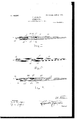
- Figure 1 is a longitudinal section through a penholder, illustrating one embodiment of the present invention.
- Fig. 2 is a top plan view of the structure shown in Fig. 1.
- Fig. 3 is a view similar to Fig. 1, showing a second embodiment of the invention.
- Fig. 4 is a section on line 4 4 of Fig. 1.
- Fig. 5 is a section on line 5 5 of Fig. 1.
- Fig. 6 is a view similar to Fig. 1, showinga third form of the invention.
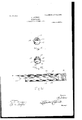
- a penholder comprising a handle 10, upon the forward end of which is fixed a sleeve 11, the free end of which is designed to receive a pen-point, (illustrated at 12.)
- a springplate or clampinglever 13 having depending ears 1& at points between its ends and at opposite sides, and through these cars and a sleeve 11 is engaged a pivot-pin 15, on which the lever is adapted to rock.
- a longitudinal slot 16 in which is disposed a wedge-shaped block 17, having a base-flange 18', that lies within the sleeve 11 and prevents the block from moving outwardly through the slot, while permitting longitudinal movement in the slot.
- the inner face of the block 17 rests against the inner 5 end portion of the lever 13.
- the end of the pen is disposed in the sleeve 11, above the forward end of the lever 13, and the block 17 is then pressed forwardly between the convergent faces of the lever and sleeve, so that the forward end of the lever is swung upwardly and clamps the pen-point against the sleeve.
- the block ' is slid rearwardl y to relieve the lever, which swings from engagement with the pen-point, which latter will drop from the holder.
- a spring clamping member 20 is provided, one end portion of which is disposed between the handle 21 and the sleeve 22, the portion of the clamping member that projects beyond the handle 21 being bent downwardly, as shown at 23, then forwardly, as shown at 24C, and then upwardly and forwardly, as shown at 25, to form a clampingjaw, between which and the inner face of the sleeve the pen-point 26 is received.
- a wedgeblock 27, corresponding to the block 17, is slidably disposed in a longitudinal slot 28 in the upper portion of the sleeve and when pressed forwardly engages the portion of the clamping member and'forces it downwardly to release the pen-point.
- a sleeve 30 is disposed upon a handle 31, and between the sleeve and handle is secured one end of a spring-plate 32, the plate extending forwardly and upwardly in the direction of the free end of the sleeve, and between which plate and sleeve is held the pen-point 33.
- a longitudinal stot 34 In the upper portion of the sleeve is a longitudinal stot 34, in which is disposed a block 35, corresponding to the block 17, and when this block is pressed forwardly in the slot 34 it bears against the spring-plate 32 and causes it to release the pen-point.
- a penholder comprising a handle, a penreceiving sleeve carried by the handle, said sleeve being provided with a longitudinal slot, a spring clamping member arranged to clamp a pen therebetween and said sleeve, a fingerblock having grooves formed in its sides, said IO ing grooves formed in its sides the said grooves being arranged to receive the sides of the said slot, said finger-block being provided with an inclined under face adapted to engage the said spring clam ping member.
Landscapes
- Clamps And Clips (AREA)
Description
No. 809,692. PATENTED JAN. 9, 1906. O. JOHNSON.
PBNHULDER.
APPLICATION FILED MAILZI, 1905.
2 SHEETS-SHEET l.
awuzuloz Wihwowo OLE JOHNSON, OF OEDARHOME, WASHINGTON.
PENHQLDER.
Specification of Letters Patent.
Patented Jan. 9, 1906.
Applicatio filed March 21,1905. Serial No. 251,289.
T at whom it may concern.-
Be it known that I, OLE J OHNSON, a citizen of the United States, residing at Oedarhome, in the county of Snohomish, State of VVashington, have invented certain new and useful Improvementsin Penholders; and I do hereby declare the following to be a full, clear, and exact description of the invention, such as will enable others skilled in the art to which it appertains to make and use the same.
This invention relates to penholders, and more particularly to ejecting penholders, the object of the invention being to provide a construction embodying but few parts wherein the pen will be so held as to be secure when in use, while it may be readily released without direct contact with the fingers of the operator.
Other objects and advantages of the invention will be understood from the following description.
In the drawings forming a portion of this specification, and in which like numerals of reference indicate similar parts in the several views, Figure 1 is a longitudinal section through a penholder, illustrating one embodiment of the present invention. Fig. 2 is a top plan view of the structure shown in Fig. 1. Fig. 3 is a view similar to Fig. 1, showing a second embodiment of the invention. Fig. 4 is a section on line 4 4 of Fig. 1. Fig. 5 is a section on line 5 5 of Fig. 1. Fig. 6 is a view similar to Fig. 1, showinga third form of the invention.
Referring now to the drawings, and more particularly to Figs. 1, 3, 1, and 5 thereof, there is shown a penholder comprising a handle 10, upon the forward end of which is fixed a sleeve 11, the free end of which is designed to receive a pen-point, (illustrated at 12.) To hold the pen-point within the end of the sleeve, there is employed a springplate or clampinglever 13, having depending ears 1& at points between its ends and at opposite sides, and through these cars and a sleeve 11 is engaged a pivot-pin 15, on which the lever is adapted to rock. In the upper face of the sleeve 11 is formed a longitudinal slot 16, in which is disposed a wedge-shaped block 17, having a base-flange 18', that lies within the sleeve 11 and prevents the block from moving outwardly through the slot, while permitting longitudinal movement in the slot. The inner face of the block 17 rests against the inner 5 end portion of the lever 13.
holder, the end of the pen is disposed in the sleeve 11, above the forward end of the lever 13, and the block 17 is then pressed forwardly between the convergent faces of the lever and sleeve, so that the forward end of the lever is swung upwardly and clamps the pen-point against the sleeve. When the pen is to be ejected or removed, the block 'is slid rearwardl y to relieve the lever, which swings from engagement with the pen-point, which latter will drop from the holder.
In the construction shown in Fig. 3 of the drawings a spring clamping member 20 is provided, one end portion of which is disposed between the handle 21 and the sleeve 22, the portion of the clamping member that projects beyond the handle 21 being bent downwardly, as shown at 23, then forwardly, as shown at 24C, and then upwardly and forwardly, as shown at 25, to form a clampingjaw, between which and the inner face of the sleeve the pen-point 26 is received. A wedgeblock 27, corresponding to the block 17, is slidably disposed in a longitudinal slot 28 in the upper portion of the sleeve and when pressed forwardly engages the portion of the clamping member and'forces it downwardly to release the pen-point.
In the construction shown in Fig. 6 a sleeve 30 is disposed upon a handle 31, and between the sleeve and handle is secured one end of a spring-plate 32, the plate extending forwardly and upwardly in the direction of the free end of the sleeve, and between which plate and sleeve is held the pen-point 33. In the upper portion of the sleeve is a longitudinal stot 34, in which is disposed a block 35, corresponding to the block 17, and when this block is pressed forwardly in the slot 34 it bears against the spring-plate 32 and causes it to release the pen-point.
It will be noted that in each instance there is employed a spring clamping-lever and a slidable thumb-operated block, which renders the clamping active or inactive, as desired. To hold the block against inward displacement, it may have -a flange at its upper portion lying against the outer face of the sleeve, as illustrated.
WVhat is claimed is 1. A penholder comprising a handle, a penreceiving sleeve carried by the handle, said sleeve being provided with a longitudinal slot, a spring clamping member arranged to clamp a pen therebetween and said sleeve, a fingerblock having grooves formed in its sides, said IO ing grooves formed in its sides the said grooves being arranged to receive the sides of the said slot, said finger-block being provided with an inclined under face adapted to engage the said spring clam ping member.
In testimony whereof I aifix my signature in 5 presence of two witnesses.
OLE JOHNSON. Witnesses:
D. O. PEARSON, A. B. KLAOLEAL.
Priority Applications (1)
| Application Number | Priority Date | Filing Date | Title |
|---|---|---|---|
| US25128905A US809692A (en) | 1905-03-21 | 1905-03-21 | Penholder. |
Applications Claiming Priority (1)
| Application Number | Priority Date | Filing Date | Title |
|---|---|---|---|
| US25128905A US809692A (en) | 1905-03-21 | 1905-03-21 | Penholder. |
Publications (1)
| Publication Number | Publication Date |
|---|---|
| US809692A true US809692A (en) | 1906-01-09 |
Family
ID=2878173
Family Applications (1)
| Application Number | Title | Priority Date | Filing Date |
|---|---|---|---|
| US25128905A Expired - Lifetime US809692A (en) | 1905-03-21 | 1905-03-21 | Penholder. |
Country Status (1)
| Country | Link |
|---|---|
| US (1) | US809692A (en) |
-
1905
- 1905-03-21 US US25128905A patent/US809692A/en not_active Expired - Lifetime
Similar Documents
| Publication | Publication Date | Title |
|---|---|---|
| US803464A (en) | Pencil-holder and book-mark. | |
| US809692A (en) | Penholder. | |
| US340382A (en) | Pen and brush holder | |
| US1256824A (en) | Cable-clamp. | |
| US500564A (en) | Guard for penholders | |
| US850234A (en) | Snap-hook. | |
| US870761A (en) | Gluing-clamp. | |
| US477105A (en) | Island | |
| US703822A (en) | Chatelaine-hook. | |
| US782081A (en) | Planer-tool. | |
| US356691A (en) | Joseph loch | |
| US884865A (en) | Pen and pencil holder. | |
| US848762A (en) | Paper-clip. | |
| US57176A (en) | Improvement in carpenters bench-hooks | |
| US710992A (en) | Trace-fastener. | |
| US648830A (en) | Pen-extractor. | |
| US816324A (en) | Printer's quoin. | |
| US901174A (en) | Wrench. | |
| US673121A (en) | Penholder. | |
| US477080A (en) | Hans sulzer | |
| US1307911A (en) | leonard and s | |
| US373506A (en) | Combined rope-clamp and tag-holder | |
| US523974A (en) | Clamp | |
| US64388A (en) | webster | |
| US974499A (en) | Loss-preventing device. |