US809462A - Lantern. - Google Patents
Lantern. Download PDFInfo
- Publication number
- US809462A US809462A US27960705A US1905279607A US809462A US 809462 A US809462 A US 809462A US 27960705 A US27960705 A US 27960705A US 1905279607 A US1905279607 A US 1905279607A US 809462 A US809462 A US 809462A
- Authority
- US
- United States
- Prior art keywords
- air
- font
- chamber
- flange
- lantern
- Prior art date
- Legal status (The legal status is an assumption and is not a legal conclusion. Google has not performed a legal analysis and makes no representation as to the accuracy of the status listed.)
- Expired - Lifetime
Links
- 238000010276 construction Methods 0.000 description 3
- 238000005096 rolling process Methods 0.000 description 2
- 229910000679 solder Inorganic materials 0.000 description 2
Images
Classifications
-
- F—MECHANICAL ENGINEERING; LIGHTING; HEATING; WEAPONS; BLASTING
- F21—LIGHTING
- F21V—FUNCTIONAL FEATURES OR DETAILS OF LIGHTING DEVICES OR SYSTEMS THEREOF; STRUCTURAL COMBINATIONS OF LIGHTING DEVICES WITH OTHER ARTICLES, NOT OTHERWISE PROVIDED FOR
- F21V35/00—Candle holders
Definitions
- stituent parts of the lantern can be stamped out separately and then connected together by interlocking parts, thus obviating the use of solder.
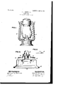
- Figure l is a completed lantern in elevation.
- Fig. 2 is a central vertical section, and
- Fig. 3 shows a detail of con struction.
- the lantern shown in the drawings to illustrate my novel construction comprises a a font 1, a burner 2, tubes 3 3, connecting with the air-chamber 4 and burner-cap 5, whose several functions are well understood and which have the form and relative positionscommon in tubularlanterns of this type.
- the font l is stamped up in the usual manner, but with a circumferential Range 6 extending out from its lower edge and at right angles thereto and a similar flange 7 around the opening for the reception of the air-chamber and burner, that is directed downwardly.
- the air chamber 4 is formed by stamping a bell-shaped piece whose lower edge 8 is adapted to enter the font and lies closeA against the flange 7.
- the burner-cone 9 is adapted to fit within the air-chamber and to extend down into the font, at the same time lying close to its lower edge 8.
- Suitable dies are now employed to bend up and roll back upon eachother the flange 7 and edges 8 and 9 in the manner shown in Fig. 2. In thisway these three parts are locked together mechanically by a simple operation and without the use of solder.
- the bottom 10 of the font is made of such size that it lies beneath the horizontal flange 6 at the base of the font.
- a shoulder 1l may be struck up from the 'bottom l0 just Within the flange 6. (See Eig. 3.)
- the flange 6 and so much of the bottom as lies below it are bent up and rolled back in the manner shown in Fig. 2 by means of tools suitable for that purpose, thus makinga tight connection between said parts.
- the air-tubes may lie exactly upon said font, and yet the holes for the air-chamber may be punched at a reasonable distance from the end of the manufactured air-cham ber, and that in rolling together the flange 7 of the font and the edge 8 of the air-chamber the registry above mentioned may be produced and maintained accurately. In rolling together the edges 7 and 8 it is clear that the air-chamber 4 will be pulled downward, so that the said registry will be produced.
- What I claim is- 1.
- a font having an opening in its upper surface provided with a downwardly-turned flange, and an air-chamber having an edge tting within and against said flange and provided-with side openings for the air-tubes of the lantern, the said two edges being rolled together whereby the said side openings are brought into registry with the to of the font when the said two edges are rol ed together.
Landscapes
- Engineering & Computer Science (AREA)
- General Engineering & Computer Science (AREA)
- Finger-Pressure Massage (AREA)
Description
UNITED sTATEs PATENT oEEioE.
ALBERT R. PRITOHARD, OF ROCHESTER, NEW YORK.
LANTERN- Specification of Letters Patent.
Patented Jan. 9, 1906.
Application filed September 22, 1905. Serial No. 279,607.
stituent parts of the lantern can be stamped out separately and then connected together by interlocking parts, thus obviating the use of solder.
In the drawings, Figure l is a completed lantern in elevation. Fig. 2 is a central vertical section, and Fig. 3 shows a detail of con struction.
The lantern shown in the drawings to illustrate my novel construction comprises a a font 1, a burner 2, tubes 3 3, connecting with the air-chamber 4 and burner-cap 5, whose several functions are well understood and which have the form and relative positionscommon in tubularlanterns of this type. The font l is stamped up in the usual manner, but with a circumferential Range 6 extending out from its lower edge and at right angles thereto and a similar flange 7 around the opening for the reception of the air-chamber and burner, that is directed downwardly.
The air chamber 4 is formed by stamping a bell-shaped piece whose lower edge 8 is adapted to enter the font and lies closeA against the flange 7. The burner-cone 9 is adapted to fit within the air-chamber and to extend down into the font, at the same time lying close to its lower edge 8. Suitable dies are now employed to bend up and roll back upon eachother the flange 7 and edges 8 and 9 in the manner shown in Fig. 2. In thisway these three parts are locked together mechanically by a simple operation and without the use of solder. Afterward the bottom 10 of the font is made of such size that it lies beneath the horizontal flange 6 at the base of the font. A shoulder 1l may be struck up from the 'bottom l0 just Within the flange 6. (See Eig. 3.) The flange 6 and so much of the bottom as lies below it are bent up and rolled back in the manner shown in Fig. 2 by means of tools suitable for that purpose, thus makinga tight connection between said parts.
It is clear that by the construction above described the holes in the air-chamber 4 for the ends of the air-tubes 3 may be brought into registry with the top edge of the font 1,
so that the air-tubes may lie exactly upon said font, and yet the holes for the air-chamber may be punched at a reasonable distance from the end of the manufactured air-cham ber, and that in rolling together the flange 7 of the font and the edge 8 of the air-chamber the registry above mentioned may be produced and maintained accurately. In rolling together the edges 7 and 8 it is clear that the air-chamber 4 will be pulled downward, so that the said registry will be produced.
What I claim is- 1. The combination of a font having an opening in its upper surface provided with a downwardly-turned flange, and an air-chamber having an edge tting within and against said flange and provided-with side openings for the air-tubes of the lantern, the said two edges being rolled together whereby the said side openings are brought into registry with the to of the font when the said two edges are rol ed together.
2. The combination of a font having an opening in its upper surface provided with a downwardly-turned ilange, an air-chamber having an edge fitting within and against said flange and provided with side openings for the air-tubes of the lantern, the said two' edges being rolled together whereby the said side openings are brought into registry with the top of the font when the said two edges are rolled together, and a burner-sup ort having an edge rolled in with the edges o the font and of the air-chamber.
ALBERT R. PRITOHARD.
Witnesses:
D. GURNEE, C. W. CARROLL.
Priority Applications (1)
| Application Number | Priority Date | Filing Date | Title |
|---|---|---|---|
| US27960705A US809462A (en) | 1905-09-22 | 1905-09-22 | Lantern. |
Applications Claiming Priority (1)
| Application Number | Priority Date | Filing Date | Title |
|---|---|---|---|
| US27960705A US809462A (en) | 1905-09-22 | 1905-09-22 | Lantern. |
Publications (1)
| Publication Number | Publication Date |
|---|---|
| US809462A true US809462A (en) | 1906-01-09 |
Family
ID=2877943
Family Applications (1)
| Application Number | Title | Priority Date | Filing Date |
|---|---|---|---|
| US27960705A Expired - Lifetime US809462A (en) | 1905-09-22 | 1905-09-22 | Lantern. |
Country Status (1)
| Country | Link |
|---|---|
| US (1) | US809462A (en) |
Cited By (1)
| Publication number | Priority date | Publication date | Assignee | Title |
|---|---|---|---|---|
| USD396891S (en) | 1996-05-17 | 1998-08-11 | Chit Hing Metal & Plastic Mfg., Ltd. | Toy lantern |
-
1905
- 1905-09-22 US US27960705A patent/US809462A/en not_active Expired - Lifetime
Cited By (1)
| Publication number | Priority date | Publication date | Assignee | Title |
|---|---|---|---|---|
| USD396891S (en) | 1996-05-17 | 1998-08-11 | Chit Hing Metal & Plastic Mfg., Ltd. | Toy lantern |
Similar Documents
| Publication | Publication Date | Title |
|---|---|---|
| US809462A (en) | Lantern. | |
| US629598A (en) | Bedstead-ball. | |
| US283177A (en) | James h | |
| US159608A (en) | Improvement in globe-holders for lamps | |
| US1202750A (en) | Tubular lantern. | |
| US442172A (en) | Burner-fastening for lamps and lanterns | |
| US1422226A (en) | Mounting naps or caps for posts, poles, or rods | |
| US1053001A (en) | Lamp-burner. | |
| US1089869A (en) | Globe or shade and holder therefor. | |
| US888139A (en) | Tubular lamp. | |
| US123981A (en) | Improvement in tubular lanterns | |
| US2078125A (en) | Tubular lantern | |
| US653038A (en) | Incandescent electric lamp. | |
| US124372A (en) | Improvement in lanterns | |
| US778915A (en) | Electric-arc lamp. | |
| US1069370A (en) | Tubular lantern. | |
| US60215A (en) | marcy | |
| US1025624A (en) | Lantern. | |
| US690113A (en) | Electric-light adjuster. | |
| US262806A (en) | Glass lamp | |
| US800336A (en) | Chimney for incandescent gas-burners. | |
| US984944A (en) | Lamp-chimney holder. | |
| US133397A (en) | Improvement in lamp-burners | |
| US923288A (en) | Lantern. | |
| US817914A (en) | Lantern. |