US8092210B2 - Mold for producing door cores - Google Patents
Mold for producing door cores Download PDFInfo
- Publication number
- US8092210B2 US8092210B2 US12/227,161 US22716107A US8092210B2 US 8092210 B2 US8092210 B2 US 8092210B2 US 22716107 A US22716107 A US 22716107A US 8092210 B2 US8092210 B2 US 8092210B2
- Authority
- US
- United States
- Prior art keywords
- framework
- mold
- rectangular framework
- rectangular
- door
- Prior art date
- Legal status (The legal status is an assumption and is not a legal conclusion. Google has not performed a legal analysis and makes no representation as to the accuracy of the status listed.)
- Expired - Fee Related, expires
Links
- 239000002245 particle Substances 0.000 claims abstract description 30
- 239000000463 material Substances 0.000 claims abstract description 26
- 239000003292 glue Substances 0.000 claims abstract description 24
- 239000002023 wood Substances 0.000 claims abstract description 22
- 230000009471 action Effects 0.000 claims abstract description 5
- 238000003825 pressing Methods 0.000 claims description 36
- 238000004519 manufacturing process Methods 0.000 claims description 30
- 239000002184 metal Substances 0.000 claims description 19
- 238000005056 compaction Methods 0.000 claims description 16
- 239000011800 void material Substances 0.000 claims description 11
- 238000009826 distribution Methods 0.000 claims description 10
- 238000010438 heat treatment Methods 0.000 claims description 8
- 238000005520 cutting process Methods 0.000 claims description 5
- 238000010408 sweeping Methods 0.000 claims description 5
- 229920001807 Urea-formaldehyde Polymers 0.000 claims description 3
- ODGAOXROABLFNM-UHFFFAOYSA-N polynoxylin Chemical compound O=C.NC(N)=O ODGAOXROABLFNM-UHFFFAOYSA-N 0.000 claims description 3
- 238000009827 uniform distribution Methods 0.000 claims description 3
- 238000002844 melting Methods 0.000 claims description 2
- 230000008018 melting Effects 0.000 claims description 2
- 239000012530 fluid Substances 0.000 claims 1
- 239000010410 layer Substances 0.000 description 41
- 238000006073 displacement reaction Methods 0.000 description 10
- 239000007787 solid Substances 0.000 description 10
- 230000006872 improvement Effects 0.000 description 8
- 238000005259 measurement Methods 0.000 description 6
- 238000000465 moulding Methods 0.000 description 6
- 238000000034 method Methods 0.000 description 5
- 230000008569 process Effects 0.000 description 5
- 230000015572 biosynthetic process Effects 0.000 description 4
- 239000002131 composite material Substances 0.000 description 4
- 230000002093 peripheral effect Effects 0.000 description 4
- 230000000694 effects Effects 0.000 description 3
- 238000009499 grossing Methods 0.000 description 3
- 238000009434 installation Methods 0.000 description 3
- 230000036961 partial effect Effects 0.000 description 3
- 230000008439 repair process Effects 0.000 description 3
- 241000761557 Lamina Species 0.000 description 2
- 230000001174 ascending effect Effects 0.000 description 2
- 238000004140 cleaning Methods 0.000 description 2
- 238000007688 edging Methods 0.000 description 2
- 238000000605 extraction Methods 0.000 description 2
- 238000009415 formwork Methods 0.000 description 2
- 239000011521 glass Substances 0.000 description 2
- 238000012423 maintenance Methods 0.000 description 2
- 239000000203 mixture Substances 0.000 description 2
- 230000002829 reductive effect Effects 0.000 description 2
- 206010003830 Automatism Diseases 0.000 description 1
- 238000004026 adhesive bonding Methods 0.000 description 1
- 230000005465 channeling Effects 0.000 description 1
- 238000010924 continuous production Methods 0.000 description 1
- 238000001816 cooling Methods 0.000 description 1
- 238000007599 discharging Methods 0.000 description 1
- 238000010030 laminating Methods 0.000 description 1
- 230000000670 limiting effect Effects 0.000 description 1
- 238000003754 machining Methods 0.000 description 1
- 230000007246 mechanism Effects 0.000 description 1
- 230000000284 resting effect Effects 0.000 description 1
- 230000002441 reversible effect Effects 0.000 description 1
- 239000002356 single layer Substances 0.000 description 1
- 230000002459 sustained effect Effects 0.000 description 1
Images


Classifications
-
- B—PERFORMING OPERATIONS; TRANSPORTING
- B27—WORKING OR PRESERVING WOOD OR SIMILAR MATERIAL; NAILING OR STAPLING MACHINES IN GENERAL
- B27N—MANUFACTURE BY DRY PROCESSES OF ARTICLES, WITH OR WITHOUT ORGANIC BINDING AGENTS, MADE FROM PARTICLES OR FIBRES CONSISTING OF WOOD OR OTHER LIGNOCELLULOSIC OR LIKE ORGANIC MATERIAL
- B27N3/00—Manufacture of substantially flat articles, e.g. boards, from particles or fibres
- B27N3/08—Moulding or pressing
- B27N3/20—Moulding or pressing characterised by using platen-presses
-
- B—PERFORMING OPERATIONS; TRANSPORTING
- B27—WORKING OR PRESERVING WOOD OR SIMILAR MATERIAL; NAILING OR STAPLING MACHINES IN GENERAL
- B27N—MANUFACTURE BY DRY PROCESSES OF ARTICLES, WITH OR WITHOUT ORGANIC BINDING AGENTS, MADE FROM PARTICLES OR FIBRES CONSISTING OF WOOD OR OTHER LIGNOCELLULOSIC OR LIKE ORGANIC MATERIAL
- B27N5/00—Manufacture of non-flat articles
Definitions
- the present invention relates to a mold (or mould) for producing door cores, which includes notable advantageous characteristics for that door manufacturing system and especially when the doors have to include voids for paneling or glazing of a known shape, number and distribution.
- the door cores are formed by pressing a mat of wood and glue conglomerate particles coming from the formers, in a gantry press with hot plates until the standard final thickness of the doors is achieved. They are then edged and, following a process of smoothing down, the laminas of fine wood that define the visible faces of the door are glued on.
- the conglomerate of wood particles and glue with which the door core is formed is not uniform but instead normally presents a sandwich-like structure, consisting of a central layer with a larger particle size, lower density and of greater thickness than the two outer layers which have finer particles, greater density and are less thick than the central layer. If the material used is DM, a single former is employed.
- the periphery of the mould receives a larger amount of wood and glue conglomerate than the rest, which makes it possible to achieve a greater density in that perimeter zone when compacting or pressing, which would even mean that it is not necessary to fit the glued thick edges in a later operation which are usually added in order to provide rigidity for the peripheral zone, particularly in the longitudinal or vertical borders which are the ones that have to receive the fittings both for the hinges and for the lock assembly.
- conglomerate boards are manufactured in a continuous process by means of formers which pour a first layer of product of greater density and smaller size particles of the wood, mixed with glue and other active products, onto the band of a conveyor belt. A second layer is added to this layer, of greater thickness, lower density and smaller size particles, and finally another layer is added analogous to the first, poured on with another former, producing a sandwich arrangement.
- This mat of wood and glue particles can consist of a single size of particle, with a uniform composition, including of a known material such as DM.
- the mat Independently of the structure and composition of the mat that will be formed following the pressing of the board to the required thickness of the door, it initially has a thickness of the order of 90-170 mm which is poured onto the conveyor belt and, once pressed in the hot plate press, a thickness is obtained is of the order of 25-40 mm for standard doors.
- the door manufacturer cuts these boards and machines them in order to produce doors of the desired measurements, eliminating the portions corresponding to the voids which have to be paneled or glazed.
- the mould for producing door cores constituting the object of the invention has special application in the production of door cores which have to possess voids for paneling or glazing, these voids being of predefined dimensions, number and position. It has the special characteristic that no material is wasted in the manufacture, or at least it does not have to be redirected towards the hoppers of the formers for being reused, since the door core remains perfectly terminated and finished, lacking just the final laminating, without requiring any machining.
- the metering devices include separate container vessels for the product and are able to move linearly on the bench for being filled up with product, being able to advance as far as being situated above the mould which occupies a fixed position at all times, with certain sequences of advance and retrocession in combination with the descent movements of the bottom of the mould in order to comply with the objective provided for, as we will comment on further below.
- the mould is formed from a fixed perimeter frame which follows the contour of the door core, or a multiple of the surface of the latter in order to obtain several door cores in the same molding phase and separate them afterwards by means of cutting.
- the height of that perimeter frame is greater than the thickness of the door core prior to compacting, in other words, it exceeds the height of the mat prior to compacting.
- a first rectangular framework integral with the same, and which fits the dimensions of the void of the perimeter frame and can slide in its interior in the manner of a plunger, whose surface includes as many apertures as there are door cores that can be produced in the mould and which are simultaneously obtained.
- these apertures are naturally smaller than the dimensions of the door core though their borders are recessed with respect to those of the latter, these apertures remaining in a concentric position with respect to the rectangular contour of them and sliding from a lower position in which the product will be received from the formers in an uncompacted thickness for filling the mould, up to another elevated position for compacting the product so that it is left with the thickness corresponding to that of the standard doors, when the press is hydraulically operated.
- second rectangular frameworks independent of each other though they can be moved telescopically inside each of the apertures of the first rectangular framework and which present the form of the surface remaining from the door core, including the respective voids if there are any for paneling or glazing, these second frameworks also being operated by hydraulic cylinders and having the same height as the first framework.
- the surface that they occupy is filled with respective blocks which remain fixed in a position flush with the fixed perimeter frame, having the same height as the latter and of such form that the second rectangular frameworks are telescopically guided in its walls.
- the second rectangular framework or frameworks include the said voids and, as they can move vertically, so their surface has to be kept constantly covered by means of the respective fixed block, mentioned earlier. If the door is compact, in other words, without any voids for paneling or glazing, the second framework is solid and its entire surface will receive the layers of conglomerate and glue.
- the upper hot plate which, throughout the entire process of charging the mould with the different products for forming the sandwich, has remained raised in order to permit the entrance and exit of the metering trays which have previously been charged with the respective product by means of the two metering devices, finally descend in order to close the mould on top.
- the charging of product has been effected in three phases as we will see further below in relation to the drawings, so that the three layers of the sandwich can be formed.
- the stripping of the mould is easily carried out after the setting time by raising up the upper hot plate and then continuing the advance of the lower platform, until the pressed board exits from the mould.
- the mould has a rectangular frame or perimeter wall which possesses different hollows or apertures with the contour of the door core to be manufactured in order to simultaneously produce several fully finished units, defining a composite mould, though it could also be a simple mould for manufacturing them on a unitary basis. Nevertheless, the previous arrangement is much more profitable.
- first rectangular framework with the contour of the door.
- second rectangular framework whose inner hollow is in turn occupied by a series of blocks that can move individually, and which can have the same or different size. These blocks can move simultaneously with the second rectangular framework, being flush with it, in order to obtain solid door cores. If any of them is kept in the elevated position during the process of charging and compaction of the mat, the voids for paneling and glazing will be formed.
- the useful surface of the first rectangular framework defines the zone where a greatest quantity of product will be received and that of the second rectangular framework defines the remaining zone of the door which is extended to the sliding blocks or pads that have not been elevated and on which the mat of wooden and glue conglomerate particles will also be deposited.
- the length of the support rods for the first rectangular framework is less than those for the second rectangular framework, the latter being equal to the support rods for the pads because they are flush with the latter rectangular framework.
- This staggering between the rectangular frameworks determines the greater thickness of charge in the perimeter zone of the door. This difference in level can be varied simply by locating some shims in the support base for the vertical rods, increasing or reducing their number.
- the rods of those cylinders are connected to each block or pad in order to be able to raise or lower it according to the type, shape and distribution of the void or voids to form for paneling or glazing, these rods passing through the upper thrust platform, just like the vertical rods.
- the first and second frameworks are merely supported by four rods arranged in the corner zones since they only have to bear the actual weight of the framework and of the charge of product, given that the compaction pressure is produced by the upper platform via some thrusting pads attached to its active face, all of them of the same height and facing each of the first and second rectangular frameworks.
- These thrusting pads also exist in correspondence with the portions or pads forming the voids for paneling or glazing.
- the thrusting pads are situated in order to thereby form a void underneath them so as to permit the cleaning and removal of remains that might have become encrusted.
- the upper thrust platform When the upper thrust platform is raised in order to start the compaction, it is the first framework that rises up first, or more accurately the first frameworks that the composite mould includes (eight by number in order to optimize the production), until it becomes flush with the second framework or frameworks, at which moment the corresponding thrusting pads establish contact with the second rectangular frameworks and they therefore rise up simultaneously.
- this small travel of staggering the compaction or pressing takes place of the perimeter zone of the door core, in each of the apertures of the composite mould and so greater density is obtained as was sought.
- the mould has to remain covered with the hot plate of the press, once the metering devices used for charging the mould have been withdrawn.
- the pads forming the voids for paneling or glazing are kept at an upper level flush with the mould of the mould, while the other ones at all times accompany the second or interior rectangular framework of the telescopic unit.
- the rectangular framework with which several units are produced in the same pressing cycle, instead of being fixed for manufacturing standard door cores, is divided into two parts; a fixed outer part perimetric to each independent unit and the other moveable inner part which can be telescopically displaced inside that unit and able to occupy two positions: an upper one which keeps it flush with the outer perimetric part for producing standard door cores and another lower position for manufacturing door cores of larger dimensions in terms of length and width, by descending by the same measure as does the first rectangular framework in order to receive a greater volume of material to press.
- each independent unit has its longitudinal walls provided with separate moveable metal strips which can descend to a greater or equal degree as does the inner moveable part in order to manufacture door cores that are oversized by one third in width, also receiving a greater charge of material to press. These latter doors are widely used as passage doors in hospitals.
- Both the moveable metal strips and the inner perimetric part are supported on vertical rods which are in turn supported on the cross-members of individual frameworks that are independent for the different units of the mould and aided by some first hydraulic cylinders and some second hydraulic cylinders for independent movements linked to the charging of product, depending on the position occupied by the metering devices for the products forming the sandwich.
- the metal strips and the moveable inner perimetric part can occupy the lowest and in turn staggered position of the first and second frameworks in order to receive a greater charge of product for forming cores of oversized doors, simply by causing the hydraulic cylinders aiding them to extend or withdraw to the desired degree depending on the order received from the automatic computer-controlled unit.
- the admission movements (descent) are sequential during the advance of the metering devices as we will see further below, since in the displacement towards one side the product for the two layers of the sandwich is discharged.
- Another improvement considered by the invention is a novel structure for the metering device which carries out the advance movements (charging all the units of the mould in the press), it then halts outside of the press so that the pressing can take place, returns to the other side with the simultaneous filling of the moulds, is stopped on this side so that the pressing can taken place, and so on successively.
- the metering device includes a large central hopper with the product that is going to constitute the central part of the sandwich, and another two smaller side hoppers containing the product for its outer layers.
- the bottom of the hoppers are some rotating rollers with blades on which the wood and glue conglomerate lies for filling the mould according to the programmed sequences.
- the central hopper contains a far greater quantity of product to discharge in the mould than do the side hoppers, the bottom is occupied by two conveyor belts which advance towards the centre where three blade rollers are found.
- FIG. 2 Is a side-on view in elevation of the same press used in the installation of FIG. 1 .
- FIG. 3 Is a schematic view in longitudinal elevation of the mould in which several door cores are produced simultaneously in a single operation, including the upper hot plate of the press in the raised position for permitting charging of the mould, along with the lower platform linked to the telescopic rectangular frameworks, also corresponding to the section along the line of cut A-A of FIG. 4 .
- FIG. 4 Is a partial view in plan of the mould for the simultaneous production of several door cores with two voids of different dimensions for fitting boards or for glazing, in accordance with FIG. 3 .
- FIG. 5 Is a sequence of movements for filling of the mould with the product to press, coming from the two formers, including in the final position (d) the upper hot plate which closed the mould in order to permit the pressing.
- FIG. 7 Is a view in plan of different door cores corresponding to the positions c, d, e and f of FIG. 6 .
- FIG. 8 Is a partial view in plan of a mould for the manufacture of door cores, in accordance with the invention, prepared for producing door cores of the shape shown in correspondence.
- FIG. 9 Is a section along the line of cut B-B of FIG. 8 .
- FIG. 10 Is a sequence of movements in four phases a), b), c) and d) for filling the mould and pressing of the product until the final thickness of the door core is obtained.
- FIG. 11 Is a view in longitudinal elevation of a mould in accordance with the invention, in which, by way of example, three solid door cores are formed simultaneously, being located beneath the gantry press and on its right is shown the extraction position of the mould out of the press for its repair or maintenance.
- FIG. 12 Is a view on a greater scale of the actual mould of FIG. 11 .
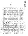
- FIG. 13 Is a view in plan of the upper thrust platform and the distribution of the thrusting pads for the first and second rectangular frameworks, along with the pads or blocks permitting the voids to be formed for paneling or glazing.
- FIG. 14 Is an enlarged view of the detail “C” of FIG. 13 .
- FIG. 15 Is a view in transverse elevation of the same mould of FIG. 11 , located beneath the gantry press.
- FIG. 16 Is a view on a greater scale of the actual mould of FIG. 15 .
- FIG. 18 Is a sectioned view in longitudinal elevation of the same mould of FIG. 17 , corresponding to section D-D of that FIG. 17 and for the specific case of simultaneous manufacture of four door cores.
- FIG. 22 Is a sectioned view in transverse elevation of the mould for four units, of the fixed part thereof.
- FIG. 24 Is a sectioned view in longitudinal elevation of the same mould for observing the heating and cooling system.
- FIG. 25 Is a sectioned view in longitudinal elevation, similar to that shown in FIG. 18 but with the internal structure of the mould more simplified in accordance with the third form of embodiment of the present invention, in other words, without including moving frameworks with ramps for elevation and descent, since solely hydraulic cylinders are used.
- FIG. 26 Is a view in sectioned transverse elevation, similar to that of FIG. 5 but also eliminating the moving frameworks with ramps as mentioned in the previous figure.
- FIG. 27 Is a view in sectioned longitudinal elevation of the carrier framework of the metering devices for filling of the mould, which slides along the upper part thereof, as is observed in FIG. 25 .
- FIG. 28 Is a view in lower plan of that shown in FIG. 17 .
- FIG. 29 Is a view in plan of that shown in FIG. 27 .
- the mould for producing door cores which the invention proposes starts from the use of the two formers 1 and 2 in which the wood and glue conglomerate is found according to the two densities and particle sizes mixed with the urea-formaldehyde glues: in the former 1 is the component of greater density which will occupy the outer layers of the sandwich of the board for the door core and in the former 2 is the component of lesser density which will remain in the central part of the board.
- the press 6 includes the upper hot plate 7 which can be moved vertically with hydraulic cylinders 8 closing the mould 9 in which the product is sequentially received from the metering devices 3 and 4 .
- FIG. 2 the press 6 can be seen in a side view with the upper hot plate 7 , being separate from the mould 2 , as in FIG. 1 .
- the mould 9 is represented schematically in elevation in FIG. 3 and in plan in FIG. 4 .
- the perimeter framework 10 is fixed and determines the walls of the mould 9 (see FIG. 4 ). Sliding in its internal perimeter is the first rectangular framework 11 which follows its contour exactly and can slide in it in the manner of a plunger. It has the same surface as the doors to form (at least three are seen in FIG. 4 since it is a partial view in plan) and it is a surface with as many apertures 12 as there are door cores to form.
- the line of union of two adjacent doors is represented with lines 13 of dashes and dots which will later on be cutting lines for the board in order to separate the different door cores formed in a single pressing, at the end of the process.
- each aperture 12 Sliding in each aperture 12 is the respective second rectangular framework 14 which has the voids 15 and 16 for paneling or glazing, of different dimension in the example of embodiment that is shown.
- the first rectangular framework 11 is defined by the spars 17 , end cross-members 18 (of which just the left-hand one can be seen in FIG. 4 ) and central cross-members 19 , the latter being double the size since, as we will see immediately below, they have to serve so that the end strips of the two consecutive door cores that they determine remain equally compacted as in the perimeter zones.
- Each one of the second frameworks 14 has some sections in the transverse direction, parallel and sliding in the sections referenced with 18 and 19 of the first rectangular framework 11 , referenced in this case with the number 20 .
- the references 21 and 22 designate the fixed blocks which occupy the position of the voids 15 and 16 for paneling or glazing.
- the rectangular framework 11 is integral with the lower platform 23 .
- the structure of the geared metering device can be seen that is very precise since half the product contained in the metering device 1 has to be discharged into the mould.
- This first layer that is poured into the mould corresponds to the lower layer of the sandwich and is referenced with 24 in position a).
- this metering device 3 undergoes a lateral displacement towards the right of FIG. 1 , with the metering device 4 remaining continuous and integral with it, in the position of discharging on the mould 9 .
- this displacement a sweeping or leveling of the mould has simultaneously taken place so that the lower layer 24 can be made homogenous and the surface of the mould is left clean.
- this second metering device 4 takes place with the thicker product or the central part of the sandwich, once both rectangular frameworks 11 and 14 have descended to occupy position b) of this FIG. 5 (in these figures just the transverse sections of the frames can be seen, corresponding to the references 18 and 20 respectively).
- This is achieved by operating the hydraulic cylinders to the preselected degree, which command the displacement of the telescopic rectangular framework 14 , located on the lower platform 23 . Due to being staggered in this charge position and the rectangular framework corresponding to the section 18 having undergone greater travel than the section 20 of the rectangular framework 14 , a greater quantity of product is received in the periphery of the mould.
- This intermediate layer distributed in this way is referenced with the number 25 .
- the return takes place of the first metering device 3 in order to be situated above the mould 9 again, at the same time as a sweep or leveling of it is carried out and the simultaneous descent takes place of both telescopic frameworks 11 and 14 (sections 18 and 20 respectively), according to a descent travel corresponding to the thickness of the remaining outer layer of the sandwich, with this finer product being discharged until the mould is filled according to the layer referenced with 26 in position c) of this FIG. 5 .
- the central layer 25 is thicker in the left-hand zone than in the right-hand zone as was intended so that, at the end of the compaction, the density of the perimeter can be greater than in the central zone. In the periphery of the voids for paneling or glazing 15 and 16 , a greater density is not needed since this is where the moulds for fitting those panels or panes of glass have to be situated.
- the metering devices 3 and 4 return to the original position outside of the mould 9 in order to permit the descent of the upper hot plate 7 until making contact with it, as corresponds to position d) of FIG. 5 .
- the upper hot plate 7 rises up and the stripping of the mould can take place as the lower platform 23 continues to rise up.
- the pressed board has exited the mould, it is withdrawn in order to commence a new cycle.
- FIG. 6 it permits the manufacture of door cores that are both solid 28 a (position a) and with one or more voids for paneling or glazing, simply by acting rapidly on certain elements of its structure, depending on the position, number and/or distribution of those voids.
- position b) Shown in position b) is a door 28 b with just a one void 29 a with a rectangular shape.
- position c) Shown in position c) is a door 28 c with two voids 29 , 29 c with straight or arched battens or moldings 30 , the straight pieces being identified with the reference 30 a and the arched ones with 30 b .
- the door 28 e has three voids 29 c with straight moldings 30 a only.
- the door 28 f has four voids 29 d , the lower one being of greater height than the rest.
- doors, voids and battens will be respectively referred to with the generic references 28 (doors), 29 (voids) and 30 (moldings), even though they might be geometrically different.
- FIG. 7 shows different door cores corresponding to the same doors as in FIG. 6 (positions c, d, e and f), which merely have to be laminated, edged and be fitted with straight or curved battens 30 , being referenced with 31 c , 31 d , 31 e and 31 f , respectively, an in general we will designate them with 31 .
- the door core 31 d and the door core 31 e have their voids at different measurements in terms of height because the first ones have to be machined in the horizontal borders which have to have curved battens fitted.
- the door 28 a of FIG. 6 would correspond to a door core 31 a not represented in this FIG. 7 and which we will call solid, in other words, without any voids for paneling or glazing.
- FIGS. 8 and 9 show, partially in plan, the mould for producing door cores in accordance with this second form of embodiment of the invention, determined by the robust frame 32 which is fixed and defines the mouth of the mould for simultaneously manufacturing three door cores 31 in this case, having three corresponding apertures 33 which have the contour and dimensions of the “door cores” 31 to manufacture (all those shown and which can be made with this mould have the same standard measurement in their contour).
- the inner surface of the second rectangular framework 35 is occupied by traverse pads or blocks provided in a battery arrangement, some of small size (referenced with 36 ), others of medium size referenced with 37 and another of larger size than the others referenced with 38 .
- FIG. 10 can be seen the different sequential phases of the manufacture of the door cores: filling of the mould and final pressing, which is carried out in the following manner:
- the product supplied from the first former, measured and weighed, passes to a metering device and from there to the mould when the rectangular frameworks 34 and 35 are flush with respect to the border of the perimeter frame 32 or filling mouth of the mould.
- a geared metering device is used that is very precise since half the product contained in the first metering device has to be discharged intro the mould.
- This layer that is poured into the mould corresponds to the lower layer of the sandwich and is referenced with 44 in the position a).
- the return takes place of the first metering device in order to be situated above the mould again, at the same time as a sweep or leveling of it is carried out and the simultaneous descent takes place of both telescopic frameworks 34 and 35 according to a descent travel in order to receive the remaining outer layer of the sandwich (position c) with the finer product until the mould is filled according to the upper layer referenced with 46 in position c) of this FIG. 10 .
- the intermediate layer 45 is thicker in the periphery as was intended so that at the end of the compaction (position d), the density of the perimeter will be greater than in the central zone.
- the lateral compaction against the fixed frame 32 means that the edge of the core is of greater density. In the periphery of the voids for paneling or glazing, a greater density is not needed since this is where the moulds for fitting those boards or panes of glass have to be situated.
- the metering devices Prior to the compaction taking place, the metering devices return to their original position outside of the mould in order to permit the descent of the hot plate 47 of the press (best seen in FIG. 11 ) as far as making contact with it, as shown by position d) of FIG. 10 .
- the two rectangular frameworks 34 and 35 that are staggered start to become flush with each other and they continue to ascend in that way until they occupy position d) of this FIG. 10 , as far as the height corresponding to the final thickness of the door core.
- the upper hot plate 47 is raised and the mould can be stripped since the lower cylinders continue to extend themselves hydraulically.
- the pressed board has exited from the mould, it is withdrawn in order to start a new cycle.
- FIGS. 11 and 15 and more enlarged in FIGS. 12 and 16 , it can be seen how the pads 36 , 37 and 38 are flush with the second framework 35 and are displaced jointly as we will see.
- a solid door core 28 is formed since the product that falls from the metering devices would fill the entire surface of the mould (in the three apertures 33 ) of FIG. 12 .
- the fixed frame 32 carrying the apertures 33 or charging mouths for the product are supported on the perimeter walls 49 .
- the first rectangular framework 34 of each aperture rests on some vertical rods 50 and the second frameworks are supported on some vertical rods 51 of greater length in order to maintain the stagger that permits a greater charge.
- the height of this stagger can be advantageously varied by inserting a greater or lesser number of shims in the base of the vertical rods. All the vertical rods in turn rest on the framework 52 of wheels 53 which are able to advance on the inclined surface of the ramps 54 attached at the top to the displaceable framework 55 which can do this due to being supported on wheels 56 .
- These wheels 56 are fitted on supports 57 fixed to the longitudinal walls 49 of the support for the fixed frame 32 (see FIG. 16 ).
- the ramps 54 are then driven by the hydraulic cylinders 61 of the press: descending in order to charge the product and ascending for the compaction.
- the cylinders 61 act on the lower metal strips 62 via the columns 63 , thereby pushing the upper platform 64 which is the carrier of the thrusting pads 65 and 66 which act directly on the first and second frameworks. Voids are therefore formed below in order to make it possible for correct cleaning to be carried out.
- This upper platform 64 is provided with holes 67 and 68 for the passage of all the rods 50 and 51 in which the first or outer rectangular framework 34 and the second or inner rectangular framework 35 are respectively supported.
- the vertical rods 50 are only located in the corner zones since they just have to support the actual weight of the framework and the product poured onto it consisting of the conglomerate of wood particles and glue.
- the vertical support rods 51 for each second rectangular framework 35 are also located in the corner zones for the same reason.
- the small hydraulic cylinders 39 , 40 and 41 which raise the pads ( 36 , 37 , 38 ) for the formation of voids also pass through openings provided in correspondence with the upper platform 64 .
- transverse metal strips 42 in which all the cylinders 39 , 40 and 41 are supported rest on other columns 69 which start from the horizontal tubular bars 70 supported on the ground.
- the reference 74 designates the rails on which the mould unit is supported by means of the wheels 75 fitted to supports 76 fastened to the longitudinal walls 49 of the support for the fixed frame 32 .
- the wheels are fitted by slightly raising the entire unit with the lower elevator cylinders 61 , causing the unit to come away from the rails 74 .
- the mould returns to its place in the press these wheels 75 are removed.
- the first and second frameworks 34 and 35 , along with the pads 36 , 37 and 38 forming the voids for paneling or glazing have a heating system like the upper hot plate 47 of the press, since the lower hot plate is materialized in them.
- door cores can be produced of standard dimension and also other door cores with special measures: with greater dimensions in length and width and other kinds of oversized doors of larger width than the previous ones.
- the first rectangular framework 34 of each aperture 33 rests on the vertical rods 50 and the second frameworks 35 are supported by vertical rods 51 of greater length in order to maintain the staggering that permits greater charge.
- this stagger instead of varying the height of this stagger by inserting a greater or lesser number of shims in the base of the vertical rods, as was considered in the previous form of embodiment ( FIGS. 6 to 16 ) now, as we will see later on, the difference in height is achieved solely by controlling the extension or withdrawal of the hydraulic cylinders, which is done by computer and in a way that is wholly precise.
- FIG. 18 Also to be seen in FIG. 18 is the pinion 58 which engages with the external rack 59 attached to the displaceable framework 55 .
- FIG. 19 it can be seen that two racks 59 have been provided, one on each side for greater stability of functioning, in which respective pinions 58 engage inserted in the outlet shaft of the drive motor 60 .
- this motor turns, the wheels 53 of the moveable frame 52 are displaced by the ramps 54 and the framework 52 rises up.
- the cylinders 39 , 40 and 41 act directly on metal strips or tubular bars 70 that are common to the four units working at the same time. Fixed to these metal strips 70 are some securing platelets 69 ′ for the pairs of rods 71 or double pairs 72 (depending on the size) which also pass through openings in the upper thrust platform 64 and which, in the case of FIG. 17 , rest below on the same framework 52 of wheels 53 as did the rods 50 and 51 .
- the present invention considers certain improvements in what we have called fixed frame 32 or mould walls, making it possible for standard doors to be obtained (those achieved with the component elements that have been explained so far in the section on the preferred form of embodiment) and also other doors of greater dimensions in length and width, as well as those that are oversized in width with respect to the more dimensioned ones and which are used as passage doors in hospitals as we have said earlier.
- the said fixed frame 32 (its section is schematically represented in FIGS. 9 and 10 by a square) is formed by or includes a fixed perimetric part 77 and another interior moveable part 78 also perimetric as we have said at the beginning of this descriptive specification.
- Reference 79 designates the metal strips that back onto the longitudinal walls of each independent unit and which can also descend in the special cases of manufacturing oversized doors, as we have already said and as we will see below.
- FIG. 18 the profile of the two metal strips 79 can be seen (one on each side of the unit of the mould) and in FIG. 17 the bottom can be seen. Both are connected to the first vertical rods 80 actuated by the pairs of first hydraulic cylinders 81 (see FIG. 25 ).
- the moveable perimetric inner part 78 is connected to some second vertical rods 82 which are raised or lowered by means of the second hydraulic cylinders 83 .
- the present invention also provides that the first and second frameworks (referenced with 34 and 35 respectively) can be actuated on using high precision hydraulic cylinders 84 and 85 like those used for the metal strips 79 and moveable perimetric part 78 and which are also controlled by computer for being positioned at the desired correct heights.
- high precision hydraulic cylinders 84 and 85 like those used for the metal strips 79 and moveable perimetric part 78 and which are also controlled by computer for being positioned at the desired correct heights.
- the hydraulic cylinders 39 , 40 and 41 for raising the pads or transverse portions 36 , 37 and 38 that are going to form the voids for paneling or glazing, if there are any, are sustained by the pairs of rods 71 or double pairs 72 supported on the cross-member 86 of the T-shapes of the supports 87 to which the elevator hydraulic cylinders 39 are secured (all of them being equal and supported in the same plane as are the cylinders 81 and 83 for governing the metal strips 79 and moveable perimeter part 78 ), and also the raising and lowering rods 50 , 51 for the first and second frameworks 34 and 35 .
- the thrust of the lower cylinders of the press is transmitted to the inner perimetric part 78 and/or to the metal strips 79 via the upper platform 64 on which other thrusting pads are provided referenced with 65 ′ and 66 ′ which are of less height than the thrusting pads 65 and 66 which press on the first and second frameworks, since the latter are of lower height than the former (metal strips 79 and inner perimetric part 78 ).
- metering devices which present the structure of FIGS. 27 to 30 , defined by a large central hopper 88 and another two side hoppers 89 which are charged with the material of the central layer of the sandwich and with the outsides thereof, respectively, the entire assembly being mounted in the sliding framework or casings 90 with wheels 91 which circulate on tracks 92 in the longitudinal upper part of all the units of the mould ( FIG. 26 ).
- the product contained in the hoppers 88 and 89 is discharged in the mould by means of rotating rollers 93 with blades, there existing three of them in the central hopper 88 and one in the side hoppers.
- the central hopper 88 has the two conveyor shelves 94 which lead the material to press on the blade rollers 93 .
- the material is distributed and is also prevented from forming clumps by means of two flight conveyors 95 (see FIG. 30 ) which move in a direction transverse to the advance of the conveyor belts 94 .
- the reference 96 designates some deflector sheets for channeling or guiding the product to the exit of the hoppers 88 and 89 .
- the sliding framework 90 of the metering devices includes two cleaner rollers 97 and 98 at its ends in the front and rear part thereof.
- the inner cleaner rollers 98 are arranged obliquely in order to effect a better sweeping and smoothing of the layer poured into the mould.
- the outer cleaner rollers 97 are longer and sweep the horizontal surface that is going to make contact with the upper hot plate 47 of the press, preventing the formation of unwanted encrustations.
- the sliding framework 90 includes some thrusters 99 at the front which withdraw the door cores 28 after the pressing and are raised higher up than the mouth of the mould by the action of the lower cylinders 61 of the press. At the same time as they are withdrawn the different mould units are charged according to a sequence of movements combined with the action of the cylinders that govern the admission of the product, as we will see further below.
- this unit is filled with the material of the hopper 88 once the frameworks and metal strips (as the case might be) have descended in order to admit the middle layer of the sandwich while the second unit is being filled with the lower layer of it.
- the cylinders descend so that the upper layer of the first unit of the mould can be filled with the product from the hopper 89 on the left of the carriage or framework 90 ; the second and third unit are filled with the intermediate layer; the fourth unit is charged with the lower layer of the sandwich of the material from the first hopper 89 . In this way, all the units are correctly filled as far as the right.
- the upper hot plate of the press descends and the pressing takes place.
- the different units of the mould are filled in the same way as mentioned above but in the reverse order and the pressed boards are simultaneously withdrawn, and so on successively.
- the heating circuits for metal strips 79 are the inner moveable perimetric part 78 , first and second frameworks 34 and 35 and pads or transverse portions ( 36 , 37 , 38 ) in order to be able to melt the glues mixed with the conglomerate wood particles.
- the access ducts 100 are rigid and vertical so that they can pass comfortably through openings 101 in the thrust platform 64 and then continue in flexible sections 102 .
- Other ducts, such as those referenced with 103 also correspond to heating systems by means of steam or hot air for the transverse portions or pads ( 36 , 37 , 38 ) for the formation of void for paneling or glazing.
- the outer fixed perimetric part 77 of the rectangular frame 32 determines a closed framework which is isolated from the peripheral wall 49 for support, by means of an isolating lamina 104 .
Landscapes
- Life Sciences & Earth Sciences (AREA)
- Engineering & Computer Science (AREA)
- Manufacturing & Machinery (AREA)
- Wood Science & Technology (AREA)
- Forests & Forestry (AREA)
- Securing Of Glass Panes Or The Like (AREA)
Applications Claiming Priority (10)
| Application Number | Priority Date | Filing Date | Title |
|---|---|---|---|
| ESP200601305 | 2006-05-19 | ||
| ES200601305 | 2006-05-19 | ||
| ES200601305A ES2289928B1 (es) | 2006-05-19 | 2006-05-19 | Molde para fabricacion de almas de puertas. |
| ESP200602572 | 2006-10-09 | ||
| ES200602572 | 2006-10-09 | ||
| ES200602572A ES2296543B1 (es) | 2006-10-09 | 2006-10-09 | Molde para fabricacion de almas de puertas. |
| ESP2006701308 | 2007-05-14 | ||
| ES200701308A ES2325712B1 (es) | 2006-10-09 | 2007-05-14 | Mejoras introducidas en la patente de invencion n. p-200602572, por: molde para fabricacion de almas de puertas. |
| ES200701308 | 2007-05-14 | ||
| PCT/ES2007/000290 WO2007135211A1 (fr) | 2006-05-19 | 2007-05-18 | Moule pour la fabrication d'âmes de portes |
Publications (2)
| Publication Number | Publication Date |
|---|---|
| US20090165961A1 US20090165961A1 (en) | 2009-07-02 |
| US8092210B2 true US8092210B2 (en) | 2012-01-10 |
Family
ID=38722985
Family Applications (1)
| Application Number | Title | Priority Date | Filing Date |
|---|---|---|---|
| US12/227,161 Expired - Fee Related US8092210B2 (en) | 2006-05-19 | 2007-05-18 | Mold for producing door cores |
Country Status (3)
| Country | Link |
|---|---|
| US (1) | US8092210B2 (fr) |
| EP (1) | EP2018944B1 (fr) |
| WO (1) | WO2007135211A1 (fr) |
Cited By (3)
| Publication number | Priority date | Publication date | Assignee | Title |
|---|---|---|---|---|
| US20150224678A1 (en) * | 2010-06-14 | 2015-08-13 | Automobili Lamborghini S.P.A. | Mold made of a composite material and process employing this mold |
| US10427393B2 (en) * | 2013-07-25 | 2019-10-01 | Masonite Corporation | Automated door assembly, press, and adhesive therefor |
| US20220088835A1 (en) * | 2020-09-23 | 2022-03-24 | Saudi Arabian Oil Company | Active self-shaping non-newtonian fluid based system and method for rapid mold tooling |
Families Citing this family (4)
| Publication number | Priority date | Publication date | Assignee | Title |
|---|---|---|---|---|
| US9931761B2 (en) * | 2013-07-25 | 2018-04-03 | Timtek, Llc | Steam pressing apparatuses, systems, and methods |
| CN108481513A (zh) * | 2018-06-12 | 2018-09-04 | 安徽安真木业有限公司 | 一种密度板压制装置 |
| KR20230020686A (ko) * | 2021-08-04 | 2023-02-13 | 현대모비스 주식회사 | 리얼우드 시트를 포함하는 차량용 크래쉬 패드 프레스 장치 및 차량용 크래쉬 패드 프레스 방법 |
| CN115946203A (zh) * | 2023-02-15 | 2023-04-11 | 江西麦丹永明木业有限公司 | 一种生态家具板的制备装置及其制造方法 |
Citations (18)
| Publication number | Priority date | Publication date | Assignee | Title |
|---|---|---|---|---|
| US2280359A (en) * | 1939-06-10 | 1942-04-21 | Curtiss Wright Corp | Sheet metal forming apparatus |
| US2410888A (en) * | 1944-03-31 | 1946-11-12 | Murray Lucy Marvosh Company | Method and apparatus for molding three-dimensional shapes from drawings |
| US3166617A (en) * | 1961-05-01 | 1965-01-19 | Werz Furnier Sperrholz | Method and apparatus for producing articles of molded particle board |
| US3534439A (en) | 1965-04-13 | 1970-10-20 | Werz Furnier Sperrholz | Molding apparatus |
| US5100601A (en) | 1989-05-23 | 1992-03-31 | Anton Heggenstaller Gmbh | Process for pressing a flexurally rigid, beam-shaped molding |
| US5192560A (en) | 1989-03-07 | 1993-03-09 | Canon Kabushiki Kaisha | Variable mold apparatus |
| US5738345A (en) * | 1993-01-27 | 1998-04-14 | General Motors Corporation | Device for generating a fixture |
| US5796620A (en) * | 1995-02-03 | 1998-08-18 | Cleveland Advanced Manufacturing Program | Computerized system for lost foam casting process using rapid tooling set-up |
| US5879612A (en) * | 1995-12-12 | 1999-03-09 | Alusuisse Technology & Management Ltd. | Process for manufacturing shaped forms of packaging |
| US5954175A (en) * | 1997-09-02 | 1999-09-21 | Northrop Grumman Corporation | Modularized parallel drivetrain |
| US6012314A (en) * | 1997-07-30 | 2000-01-11 | Northrop Grumman Corporation | Individual motor pin module |
| US6230409B1 (en) | 1998-03-31 | 2001-05-15 | Earth Products Limited | Molded building panel and method of construction |
| WO2005046950A1 (fr) | 2003-11-13 | 2005-05-26 | Swedwood International Ab | Panneau de particules |
| US7159836B2 (en) * | 2003-06-30 | 2007-01-09 | Owens Corning Fiberglas Technology, Inc. | Flow through molding apparatus and method |
| US7255550B2 (en) * | 2005-05-20 | 2007-08-14 | Hon Hai Precision Industry Co., Ltd. | Press-molding mold |
| US7311512B2 (en) * | 2004-03-22 | 2007-12-25 | Seiko Epson Corporation | Three-dimensional hard copy apparatus |
| US7395844B2 (en) * | 2005-04-27 | 2008-07-08 | Olympus Corporation | Processing apparatus and method of processing |
| US20080251975A1 (en) * | 2007-04-12 | 2008-10-16 | Purdue Research Foundation | Molding processes and tool therefor |
Family Cites Families (3)
| Publication number | Priority date | Publication date | Assignee | Title |
|---|---|---|---|---|
| DE880482C (de) * | 1950-04-21 | 1953-06-22 | Heinrich Dr-Ing Strombeck | Verfahren und Vorrichtung zur Herstellung von Formkoerpern aus Holzspaenen mit organischen Bindemitteln |
| DE10159107A1 (de) * | 2001-12-01 | 2003-06-12 | Joachim Gerstein | Verfahren und Vorrichtung zur Herstellung von Bilderrahmen |
| US7314534B2 (en) * | 2003-07-23 | 2008-01-01 | Masonite Corporation | Method of making multi-ply door core, multi-ply door core, and door manufactured therewith |
-
2007
- 2007-05-18 EP EP07765870.6A patent/EP2018944B1/fr not_active Not-in-force
- 2007-05-18 WO PCT/ES2007/000290 patent/WO2007135211A1/fr active Application Filing
- 2007-05-18 US US12/227,161 patent/US8092210B2/en not_active Expired - Fee Related
Patent Citations (18)
| Publication number | Priority date | Publication date | Assignee | Title |
|---|---|---|---|---|
| US2280359A (en) * | 1939-06-10 | 1942-04-21 | Curtiss Wright Corp | Sheet metal forming apparatus |
| US2410888A (en) * | 1944-03-31 | 1946-11-12 | Murray Lucy Marvosh Company | Method and apparatus for molding three-dimensional shapes from drawings |
| US3166617A (en) * | 1961-05-01 | 1965-01-19 | Werz Furnier Sperrholz | Method and apparatus for producing articles of molded particle board |
| US3534439A (en) | 1965-04-13 | 1970-10-20 | Werz Furnier Sperrholz | Molding apparatus |
| US5192560A (en) | 1989-03-07 | 1993-03-09 | Canon Kabushiki Kaisha | Variable mold apparatus |
| US5100601A (en) | 1989-05-23 | 1992-03-31 | Anton Heggenstaller Gmbh | Process for pressing a flexurally rigid, beam-shaped molding |
| US5738345A (en) * | 1993-01-27 | 1998-04-14 | General Motors Corporation | Device for generating a fixture |
| US5796620A (en) * | 1995-02-03 | 1998-08-18 | Cleveland Advanced Manufacturing Program | Computerized system for lost foam casting process using rapid tooling set-up |
| US5879612A (en) * | 1995-12-12 | 1999-03-09 | Alusuisse Technology & Management Ltd. | Process for manufacturing shaped forms of packaging |
| US6012314A (en) * | 1997-07-30 | 2000-01-11 | Northrop Grumman Corporation | Individual motor pin module |
| US5954175A (en) * | 1997-09-02 | 1999-09-21 | Northrop Grumman Corporation | Modularized parallel drivetrain |
| US6230409B1 (en) | 1998-03-31 | 2001-05-15 | Earth Products Limited | Molded building panel and method of construction |
| US7159836B2 (en) * | 2003-06-30 | 2007-01-09 | Owens Corning Fiberglas Technology, Inc. | Flow through molding apparatus and method |
| WO2005046950A1 (fr) | 2003-11-13 | 2005-05-26 | Swedwood International Ab | Panneau de particules |
| US7311512B2 (en) * | 2004-03-22 | 2007-12-25 | Seiko Epson Corporation | Three-dimensional hard copy apparatus |
| US7395844B2 (en) * | 2005-04-27 | 2008-07-08 | Olympus Corporation | Processing apparatus and method of processing |
| US7255550B2 (en) * | 2005-05-20 | 2007-08-14 | Hon Hai Precision Industry Co., Ltd. | Press-molding mold |
| US20080251975A1 (en) * | 2007-04-12 | 2008-10-16 | Purdue Research Foundation | Molding processes and tool therefor |
Non-Patent Citations (1)
| Title |
|---|
| International Search Report issued Sep. 27, 2007 in the International (PCT) Application of which the present application is the U.S. National Stage. |
Cited By (5)
| Publication number | Priority date | Publication date | Assignee | Title |
|---|---|---|---|---|
| US20150224678A1 (en) * | 2010-06-14 | 2015-08-13 | Automobili Lamborghini S.P.A. | Mold made of a composite material and process employing this mold |
| US10960579B2 (en) * | 2010-06-14 | 2021-03-30 | Automobili Lamborghini S.P.A. | Mold made of a composite material and process employing this mold |
| US10427393B2 (en) * | 2013-07-25 | 2019-10-01 | Masonite Corporation | Automated door assembly, press, and adhesive therefor |
| US20220088835A1 (en) * | 2020-09-23 | 2022-03-24 | Saudi Arabian Oil Company | Active self-shaping non-newtonian fluid based system and method for rapid mold tooling |
| US11577431B2 (en) * | 2020-09-23 | 2023-02-14 | Saudi Arabian Oil Company | Active self-shaping non-Newtonian fluid based system and method for rapid mold tooling |
Also Published As
| Publication number | Publication date |
|---|---|
| EP2018944A1 (fr) | 2009-01-28 |
| WO2007135211A1 (fr) | 2007-11-29 |
| EP2018944B1 (fr) | 2014-03-05 |
| EP2018944A4 (fr) | 2012-02-22 |
| US20090165961A1 (en) | 2009-07-02 |
Similar Documents
| Publication | Publication Date | Title |
|---|---|---|
| US8092210B2 (en) | Mold for producing door cores | |
| DE202010002946U1 (de) | Betonformlingherstellvorrichtung | |
| US3833331A (en) | Apparatus for forming building blocks | |
| US10603817B2 (en) | Fully automated mold change with product height change | |
| CN109333387B (zh) | 一种软磨片回转式生产线及其控制方法 | |
| US2624928A (en) | Press for molding concrete building elements | |
| CN101489745B (zh) | 用于制造门芯的模具 | |
| DE10163323A1 (de) | Verfahren und Vorrichtung zur Herstellung von Mauersteinen | |
| CA1046246A (fr) | Appareils de fabrication de panneaux de platre | |
| CA2800739C (fr) | Panneau alveolaire et moule destine a sa fabrication | |
| JP5087078B2 (ja) | 扉の芯を生産するための型 | |
| US4421466A (en) | Apparatus for molding concrete articles and the like | |
| ES2296543B1 (es) | Molde para fabricacion de almas de puertas. | |
| ES2328203B2 (es) | Molde para fabricacion de tableros atamborados y tablero atamborado. | |
| EP1375098A2 (fr) | Méthode et station de remplissage pour obturer de cavités | |
| EP0918604B1 (fr) | Dispositif pour produire des materiaux de construction etuves | |
| EP0927615B1 (fr) | Installation pour l'obtention de matériaux de construction durcis à la vapeur | |
| CN217474792U (zh) | 可快换模板和射砂板同时用于不同铁型覆砂造型的装置 | |
| RU2051795C1 (ru) | Устройство для укладки и уплотнения бетонных смесей | |
| EP4185756A1 (fr) | Système d'impression 3d et procédé de construction automatique d'un bâtiment | |
| HU202143B (en) | Method and apparatus for producing bricks from earth base material |
Legal Events
| Date | Code | Title | Description |
|---|---|---|---|
| ZAAA | Notice of allowance and fees due |
Free format text: ORIGINAL CODE: NOA |
|
| ZAAB | Notice of allowance mailed |
Free format text: ORIGINAL CODE: MN/=. |
|
| STCF | Information on status: patent grant |
Free format text: PATENTED CASE |
|
| FEPP | Fee payment procedure |
Free format text: PATENT HOLDER CLAIMS MICRO ENTITY STATUS, ENTITY STATUS SET TO MICRO (ORIGINAL EVENT CODE: STOM); ENTITY STATUS OF PATENT OWNER: MICROENTITY Free format text: PAYOR NUMBER ASSIGNED (ORIGINAL EVENT CODE: ASPN); ENTITY STATUS OF PATENT OWNER: MICROENTITY |
|
| FPAY | Fee payment |
Year of fee payment: 4 |
|
| MAFP | Maintenance fee payment |
Free format text: PAYMENT OF MAINTENANCE FEE, 8TH YEAR, MICRO ENTITY (ORIGINAL EVENT CODE: M3552); ENTITY STATUS OF PATENT OWNER: MICROENTITY Year of fee payment: 8 |
|
| FEPP | Fee payment procedure |
Free format text: MAINTENANCE FEE REMINDER MAILED (ORIGINAL EVENT CODE: REM.); ENTITY STATUS OF PATENT OWNER: MICROENTITY |
|
| LAPS | Lapse for failure to pay maintenance fees |
Free format text: PATENT EXPIRED FOR FAILURE TO PAY MAINTENANCE FEES (ORIGINAL EVENT CODE: EXP.); ENTITY STATUS OF PATENT OWNER: MICROENTITY |
|
| STCH | Information on status: patent discontinuation |
Free format text: PATENT EXPIRED DUE TO NONPAYMENT OF MAINTENANCE FEES UNDER 37 CFR 1.362 |
|
| FP | Lapsed due to failure to pay maintenance fee |
Effective date: 20240110 |