US8091725B2 - Anti-twist device for a container - Google Patents
Anti-twist device for a container Download PDFInfo
- Publication number
- US8091725B2 US8091725B2 US10/587,145 US58714504A US8091725B2 US 8091725 B2 US8091725 B2 US 8091725B2 US 58714504 A US58714504 A US 58714504A US 8091725 B2 US8091725 B2 US 8091725B2
- Authority
- US
- United States
- Prior art keywords
- container
- drive
- sealing
- connecting piece
- twist
- Prior art date
- Legal status (The legal status is an assumption and is not a legal conclusion. Google has not performed a legal analysis and makes no representation as to the accuracy of the status listed.)
- Expired - Fee Related, expires
Links
Images


Classifications
-
- F—MECHANICAL ENGINEERING; LIGHTING; HEATING; WEAPONS; BLASTING
- F01—MACHINES OR ENGINES IN GENERAL; ENGINE PLANTS IN GENERAL; STEAM ENGINES
- F01P—COOLING OF MACHINES OR ENGINES IN GENERAL; COOLING OF INTERNAL-COMBUSTION ENGINES
- F01P11/00—Component parts, details, or accessories not provided for in, or of interest apart from, groups F01P1/00 - F01P9/00
- F01P11/02—Liquid-coolant filling, overflow, venting, or draining devices
- F01P11/0204—Filling
- F01P11/0209—Closure caps
- F01P11/0247—Safety; Locking against opening
- F01P2011/0261—Safety; Locking against opening activated by temperature
-
- F—MECHANICAL ENGINEERING; LIGHTING; HEATING; WEAPONS; BLASTING
- F01—MACHINES OR ENGINES IN GENERAL; ENGINE PLANTS IN GENERAL; STEAM ENGINES
- F01P—COOLING OF MACHINES OR ENGINES IN GENERAL; COOLING OF INTERNAL-COMBUSTION ENGINES
- F01P11/00—Component parts, details, or accessories not provided for in, or of interest apart from, groups F01P1/00 - F01P9/00
- F01P11/02—Liquid-coolant filling, overflow, venting, or draining devices
- F01P11/0204—Filling
- F01P11/0209—Closure caps
- F01P11/0247—Safety; Locking against opening
- F01P2011/0266—Safety; Locking against opening activated by pressure
-
- Y—GENERAL TAGGING OF NEW TECHNOLOGICAL DEVELOPMENTS; GENERAL TAGGING OF CROSS-SECTIONAL TECHNOLOGIES SPANNING OVER SEVERAL SECTIONS OF THE IPC; TECHNICAL SUBJECTS COVERED BY FORMER USPC CROSS-REFERENCE ART COLLECTIONS [XRACs] AND DIGESTS
- Y10—TECHNICAL SUBJECTS COVERED BY FORMER USPC
- Y10S—TECHNICAL SUBJECTS COVERED BY FORMER USPC CROSS-REFERENCE ART COLLECTIONS [XRACs] AND DIGESTS
- Y10S220/00—Receptacles
- Y10S220/32—Radiator cap
-
- Y—GENERAL TAGGING OF NEW TECHNOLOGICAL DEVELOPMENTS; GENERAL TAGGING OF CROSS-SECTIONAL TECHNOLOGIES SPANNING OVER SEVERAL SECTIONS OF THE IPC; TECHNICAL SUBJECTS COVERED BY FORMER USPC CROSS-REFERENCE ART COLLECTIONS [XRACs] AND DIGESTS
- Y10—TECHNICAL SUBJECTS COVERED BY FORMER USPC
- Y10S—TECHNICAL SUBJECTS COVERED BY FORMER USPC CROSS-REFERENCE ART COLLECTIONS [XRACs] AND DIGESTS
- Y10S220/00—Receptacles
- Y10S220/33—Gasoline tank cap
Definitions
- the present invention relates to an anti-twist device for a sealing cap, mountable or mounted on a fixed connecting piece of a container, in particular a motor vehicle radiator.
- the anti-twist stop is embodied as a coupling insert, whose axial disengagement and engagement motion is derived from a pressure-dependent axial motion of a valve body of the valve assembly.
- This type of drive of the anti-twist stop is relatively complicated, and it cannot be used particularly whenever there is no valve assembly embodied as an excess/negative pressure combination.
- a simplified anti-twist stop between the sealing element of the sealing cap on the one hand and the container on the other is described in German Patent Disclosure DE 101 64 669 A1, in which a drive, accommodated inside the container, is provided with a blocking bolt which plunge directly into the sealing element of the sealing cap.
- the anti-twist device is designed such that rotational locking is done between the sealing cap and the container.
- a disadvantage of this is that it cannot be told in advance whether the sealing cap is only firmly seated or is actually locked, which means that if too much force is expended, the blocking bolt can be broken off.
- the object of the present invention is therefore to provide an anti-twist device for a sealing cap, mountable or mounted on a fixed connecting piece of a container, in particular a motor vehicle radiator, of the type defined at the outset which on the one hand, instead of a locking function has an idle-travel function and on the other is nevertheless constructed more simply from the standpoint of both engineering and production.
- an anti-twist device for a sealing cap mountable or mounted on a fixed connecting piece of a container, in particular a motor vehicle radiator
- the anti-twist stop is actuatable by means of a drive triggered by the operating data in the container, the drive being accommodated inside the container near the external cap part.
- a rotation preventer in the form of an idle-travel connection is obtained between the grip element and the sealing element of the external cap part, and furthermore, a drive connection acting on this anti-twist stop is obtained, which originates from inside the container and is thus directly exposed to the pressure and temperature present in the container. There is no mechanical connection, which might possibly be damaged, between the container and the sealing cap.
- a drive part is disposed on a circumferential region of a container wall adjacent to the connecting piece.
- the drive may be formed by two or more drive parts, distributed preferably uniformly over the circumference of a container wall adjacent to the connecting piece.
- the individual drive parts can be held in position for instance by a ring, or in the manner whereby each of two drive parts is disposed, held separately, inside the container and tangentially below the counterpart sealing element of the connecting piece, so that a spatially direct association is achieved between the drive in the container and the anti-twist stop in the sealing cap.
- each drive part is received in a housing that is held suspended from the container wall.
- the housing is held in pressure tight fashion in a recess in the container wall.
- the housing is comprised of a hood part, protruding from the container wall, and a basket part whose bottom is provided with an opening.
- the hood part is provided with an axial leadthrough, which penetrates the container wall and is held in it in pressure tight fashion.
- the hood part and the basket part are joined, locking over and in one another.
- Each drive part has a vertically oriented actuation bolt, which, facing toward the anti-twist stop, is covered by a diaphragm, which is fastened tightly between the hood part and the basket part.
- the drive part is pressure-controlled, and its activation bolt is spring-loaded in the opposite direction, the drive in the container is pressure-controlled; it is also possible for it to be thermally controlled.
- the present invention also relates to a unit comprising a container with a connecting piece and a sealing cap, or comprising a container connecting piece and a sealing cap, which is provided with an anti-twist device of the invention.
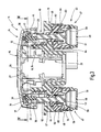
- FIG. 1 in a schematic longitudinal section, a sealing cap, mounted on a motor vehicle radiator, with a pressure-controlled anti-twist stop in the coupled state, in a preferred exemplary embodiment of the present invention
- FIG. 2 a section taken along the line 11 - 11 of FIG. 1 ;
- FIG. 3 a view corresponding to FIG. 1 , but with the anti-twist stop in the uncoupled state;
- FIG. 4 a section taken along the line IV-IV of FIG. 3 .
- the anti-twist device 10 serves the purpose of operationally controlled prevention of unscrewing a sealing cap 11 from the sealing connecting piece 12 of a container 13 , such as a motor vehicle radiator, whenever because of the operating state of the container (elevated pressure or temperature) unscrewing the sealing cap 11 from the container connecting piece 12 can involve risks to the user.
- the sealing cap 11 has an external cap part 14 , which is provided with a grip element 16 and a sealing element 17 , and the sealing element in this case has a female thread 18 for screwing the sealing cap 11 onto and unscrewing it from the opening of the sealing connecting piece 12 , provided with a male thread 19 , of the motor vehicle radiator 13 or other container.
- the sealing element 17 may be provided with a bayonet-type cap, which can be connected to a corresponding sealing part on the connecting piece.
- an internal cap part 21 is disposed, which is held rotatably relative to the sealing element 17 of the external cap part 14 but firmly held axially.
- the internal cap part 21 may, in a manner not shown, be embodied as a valve pot, which can for instance have an excess/negative pressure valve assembly, whose excess pressure valve is triggerable in a single stage or in two stages.
- the grip element 16 is fitted over the sealing element 17 and engages it from below annularly; an internal annular extension 23 of the grip element 16 engages an outer annular extension 34 of the sealing element 17 from below.
- the grip element 16 is held freely rotatably relative to the sealing element 17 , but is axially fixed.
- the counterpart support or contact is formed by the two contacting top walls 26 and 27 of the grip element 16 and sealing element 17 , respectively.
- an indexable or coupleable anti-twist stop 30 is provided between the grip element 16 and the sealing element 17 .
- the anti-twist stop 30 here has two diametrically opposed engageable and disengageable coupling elements 31 , each of which in the engagement position in FIG. 1 is loaded by a compression spring 29 .
- Each coupling element 31 has one coupling bolt 36 , oriented axially to the underside of the sealing element 17 , and one approximately trapezoidal coupling locking bar 37 firmly joined to it.
- the coupling bolt 36 of the coupling element 31 which in longitudinal section is approximately T-shaped, is held axially movably but in a manner fixed against relative rotation inside the sealing element 17 , for instance in a bore.
- the coupling locking bar 37 radially on its outside, has a set of teeth 43 , which is brought into connection, in a manner fixed against relative rotation, with a radially inner set of teeth 44 on an annular collar 33 , extending all the way around on the inside, of the grip element 16 as shown in FIGS. 1 and 2 .
- FIGS. 1 and 2 In other words, in the pressureless outset state of the container 13 , as shown in FIGS.
- the coupling locking bar 37 under the action of the compression spring 39 , rests by positive engagement in the annular collar 33 of the grip element 16 , and in this engaged coupling position, it is located on an annular wall 32 of the sealing element 17 .
- the free end of the coupling bolt 36 remote from the compression spring 39 and the coupling locking bar 37 , is located inside an annular chamber of the sealing element 17 , which chamber is open toward the container 13 .
- a drive 45 is provided in the container 13 , on a wall 46 of the container 13 that surrounds the sealing connecting piece 12 below the male thread 19 , and inside the container 13 .
- the drive 45 here comprises two drive parts 47 , which on two diametrically opposed sides of the annular wall 46 surrounding the sealing connecting piece 12 , suspended from the underside of this wall in the container 13 .
- Each drive part has a cylindrical housing 48 , which hangs downward from the annular wall 46 and which on its bottom 49 has an opening 51 into the container interior.
- the two drive parts 47 in parallel axial alignment, are located below the coupling bolt 36 of the applicable coupling element 31 .
- a piston 52 with an axial tappet 53 and a compression spring 54 are provided, in the form of an upside-down T, inside the housing 48 .
- the compression spring 45 which is braced on an inner side of the housing 48 , presses the piston 52 against the bottom 49 of the housing 48 .
- the housing 48 substantially comprises a hood part 56 , which is provided with a leadthrough 57 , and a basket part 58 , whose bottom 49 has the annularly disposed openings 51 . By its end remote from the bottom 49 , the basket part 58 is thrust over the end of the hood part 56 remote from the leadthrough 57 and is held in locking fashion.
- a diaphragm 59 is fastened between an annular end face of the hood part 56 and an annular shoulder of the basket part 58 and wraps around the piston 52 and thus seals off the housing interior from the container interior.
- the leadthrough 57 of the hood part 56 is press-fitted into a bore 61 of the annular wall 46 of the container 13 or firmly held in some other way such that a tight connection results.
- the annular face of the hood part 56 around the leadthrough 57 is provided with an O-ring 62 , with which a sealing action can be attained in such a way that the hood part 56 is locked by positive engagement at the annular point 65 between container walls 63 , 64 that protrude perpendicular to the annular wall 46 .
- the leadthrough 57 of the hood part 56 is such that the tappet 53 of the piston 52 of the drive part 47 , in the pressureless state shown in FIG. 1 , penetrates the leadthrough 57 but does not protrude past it.
- the two drive parts 47 are exposed to the internal pressure in the container 13 . If the internal pressure in the container 13 exceeds the specified allowable pressure, the piston 52 is moved with the tappet 53 in the axial direction A; the tappet 53 meets the coupling bolt 36 and disengages the coupling locking bar 37 of the coupling element 31 from its connection, fixed against relative rotation, with the grip element 16 ( FIGS. 3 and 4 ). In this position of the coupling locking bar 37 , disengaged from the connection that is fixed against relative rotation, the grip element 16 rotates idly relative to the sealing element 17 , so that unscrewing the sealing cap 11 from the sealing connecting piece 12 of the container 13 is not possible.
- a stop is integrated into the sealing cap, and this assures that in the state in which the sealing cap 11 is screwed onto the sealing connecting piece 12 , the two coupling elements 31 of the anti-twist stop 30 are located axially diametrically opposite the two drive parts 47 of the drive 45 .
Landscapes
- Engineering & Computer Science (AREA)
- Chemical & Material Sciences (AREA)
- Combustion & Propulsion (AREA)
- Mechanical Engineering (AREA)
- General Engineering & Computer Science (AREA)
- Closures For Containers (AREA)
- Pressure Vessels And Lids Thereof (AREA)
- Burglar Alarm Systems (AREA)
Applications Claiming Priority (4)
| Application Number | Priority Date | Filing Date | Title |
|---|---|---|---|
| DE2020040001333.9 | 2004-01-22 | ||
| DE202004001333U DE202004001333U1 (de) | 2004-01-22 | 2004-01-22 | Abschraubsicherungsvorrichtung für Behälter |
| DE202004001333U | 2004-01-22 | ||
| PCT/EP2004/012573 WO2005073532A1 (fr) | 2004-01-22 | 2004-11-05 | Dispositif d'antidevissage destine a un contenant |
Publications (2)
| Publication Number | Publication Date |
|---|---|
| US20070289969A1 US20070289969A1 (en) | 2007-12-20 |
| US8091725B2 true US8091725B2 (en) | 2012-01-10 |
Family
ID=34638909
Family Applications (1)
| Application Number | Title | Priority Date | Filing Date |
|---|---|---|---|
| US10/587,145 Expired - Fee Related US8091725B2 (en) | 2004-01-22 | 2004-11-05 | Anti-twist device for a container |
Country Status (5)
| Country | Link |
|---|---|
| US (1) | US8091725B2 (fr) |
| EP (1) | EP1706611B1 (fr) |
| AT (1) | ATE503093T1 (fr) |
| DE (2) | DE202004001333U1 (fr) |
| WO (1) | WO2005073532A1 (fr) |
Families Citing this family (1)
| Publication number | Priority date | Publication date | Assignee | Title |
|---|---|---|---|---|
| US7791055B2 (en) * | 2006-07-10 | 2010-09-07 | Micron Technology, Inc. | Electron induced chemical etching/deposition for enhanced detection of surface defects |
Citations (3)
| Publication number | Priority date | Publication date | Assignee | Title |
|---|---|---|---|---|
| DE19946845A1 (de) | 1999-09-30 | 2001-04-19 | Blau Kunststofftechnik Zweigni | Verschlußdeckel |
| DE10035729A1 (de) | 2000-07-22 | 2002-01-31 | Heinrich Reutter | Verschlussdeckel mit Verdrehsicherung |
| DE10164669A1 (de) | 2001-12-22 | 2003-07-03 | Reutter Heinrich | Abschraubsicherungsvorrichtung für Behälter |
Family Cites Families (2)
| Publication number | Priority date | Publication date | Assignee | Title |
|---|---|---|---|---|
| US5407039A (en) * | 1993-06-04 | 1995-04-18 | Alper; Brad | Wheeled luggage case |
| US6241313B1 (en) * | 2000-05-18 | 2001-06-05 | Randall G. Lenz | Child seat attachable to a suitcase |
-
2004
- 2004-01-22 DE DE202004001333U patent/DE202004001333U1/de not_active Expired - Lifetime
- 2004-11-05 AT AT04797677T patent/ATE503093T1/de active
- 2004-11-05 DE DE502004012338T patent/DE502004012338D1/de active Active
- 2004-11-05 US US10/587,145 patent/US8091725B2/en not_active Expired - Fee Related
- 2004-11-05 WO PCT/EP2004/012573 patent/WO2005073532A1/fr active Application Filing
- 2004-11-05 EP EP04797677A patent/EP1706611B1/fr not_active Not-in-force
Patent Citations (4)
| Publication number | Priority date | Publication date | Assignee | Title |
|---|---|---|---|---|
| DE19946845A1 (de) | 1999-09-30 | 2001-04-19 | Blau Kunststofftechnik Zweigni | Verschlußdeckel |
| DE10035729A1 (de) | 2000-07-22 | 2002-01-31 | Heinrich Reutter | Verschlussdeckel mit Verdrehsicherung |
| US20030183632A1 (en) * | 2000-07-22 | 2003-10-02 | Heinrich Reutter | Closure cap provided with anti-twisting |
| DE10164669A1 (de) | 2001-12-22 | 2003-07-03 | Reutter Heinrich | Abschraubsicherungsvorrichtung für Behälter |
Also Published As
| Publication number | Publication date |
|---|---|
| DE502004012338D1 (de) | 2011-05-05 |
| ATE503093T1 (de) | 2011-04-15 |
| WO2005073532A1 (fr) | 2005-08-11 |
| US20070289969A1 (en) | 2007-12-20 |
| EP1706611B1 (fr) | 2011-03-23 |
| EP1706611A1 (fr) | 2006-10-04 |
| DE202004001333U1 (de) | 2005-06-02 |
Similar Documents
| Publication | Publication Date | Title |
|---|---|---|
| US8087529B2 (en) | Safety closure for steam pressurized containers of household appliances | |
| US6772989B2 (en) | Maintenance-easy two-port valve | |
| EP0309131B1 (fr) | Soupape de vidange du lubrifiant | |
| US4215790A (en) | Guard for compressed air fitting bowl | |
| US7435345B2 (en) | Element replacement type filter | |
| US11305213B2 (en) | Filter element with torsion lock and/or sliding piston, assembly and methods | |
| JP5408453B2 (ja) | 内圧を受ける安全機能付き容器用の蓋及び燃料タンク用の閉鎖蓋 | |
| US7380681B2 (en) | Sealing lid for motor vehicle radiator | |
| US8091725B2 (en) | Anti-twist device for a container | |
| US6349842B1 (en) | Cover fastenable on a container connection | |
| JPH0444104B2 (fr) | ||
| US7353965B2 (en) | Closure cap provided with anti-twisting | |
| US5590680A (en) | External valve operating means | |
| US20040056034A1 (en) | Sealing gap | |
| US6729271B1 (en) | Closure cap for a motor vehicle radiator | |
| US4336824A (en) | Cartridge valve | |
| US6073791A (en) | Closure cap with temperature-dependent unscrewing protection | |
| US6024201A (en) | Disengaging mechanism for a friction clutch | |
| CA2424632C (fr) | Raccord pour cartouche de carburant et cartouche cloueuse a piston a gaz comprime | |
| US20040099668A1 (en) | Sealing cover with an anti-unscrew safety device | |
| US20050121453A1 (en) | Unscrewing security device for containers | |
| JP4083022B2 (ja) | 内燃機関のガス交換弁の軸端部と弁作動装置のスリーブ状の作動ピストンとの間の結合部 | |
| US6742667B1 (en) | Closure cap for a radiator of a motor vehicle | |
| EP1530002B1 (fr) | Réservoir pour fluide sous pression avec protection contre la contamination | |
| US20050011893A1 (en) | Closure cap for an automotive radiator |
Legal Events
| Date | Code | Title | Description |
|---|---|---|---|
| AS | Assignment |
Owner name: REUTTER METALLWARENFABRIK GMBH, GERMANY Free format text: ASSIGNMENT OF ASSIGNORS INTEREST;ASSIGNORS:KORBER, RENE;FUCHS, HELMUT;SIGNING DATES FROM 20060205 TO 20110728;REEL/FRAME:027047/0156 |
|
| STCF | Information on status: patent grant |
Free format text: PATENTED CASE |
|
| FEPP | Fee payment procedure |
Free format text: PAYOR NUMBER ASSIGNED (ORIGINAL EVENT CODE: ASPN); ENTITY STATUS OF PATENT OWNER: SMALL ENTITY |
|
| FPAY | Fee payment |
Year of fee payment: 4 |
|
| FEPP | Fee payment procedure |
Free format text: MAINTENANCE FEE REMINDER MAILED (ORIGINAL EVENT CODE: REM.); ENTITY STATUS OF PATENT OWNER: SMALL ENTITY |
|
| LAPS | Lapse for failure to pay maintenance fees |
Free format text: PATENT EXPIRED FOR FAILURE TO PAY MAINTENANCE FEES (ORIGINAL EVENT CODE: EXP.); ENTITY STATUS OF PATENT OWNER: SMALL ENTITY |
|
| STCH | Information on status: patent discontinuation |
Free format text: PATENT EXPIRED DUE TO NONPAYMENT OF MAINTENANCE FEES UNDER 37 CFR 1.362 |
|
| FP | Lapsed due to failure to pay maintenance fee |
Effective date: 20200110 |