US809043A - Regulating-hinge for piano swinging frames. - Google Patents
Regulating-hinge for piano swinging frames. Download PDFInfo
- Publication number
- US809043A US809043A US20988304A US1904209883A US809043A US 809043 A US809043 A US 809043A US 20988304 A US20988304 A US 20988304A US 1904209883 A US1904209883 A US 1904209883A US 809043 A US809043 A US 809043A
- Authority
- US
- United States
- Prior art keywords
- hinge
- section
- frame
- sections
- swinging
- Prior art date
- Legal status (The legal status is an assumption and is not a legal conclusion. Google has not performed a legal analysis and makes no representation as to the accuracy of the status listed.)
- Expired - Lifetime
Links
- 238000010276 construction Methods 0.000 description 2
- 229910001369 Brass Inorganic materials 0.000 description 1
- 229910000831 Steel Inorganic materials 0.000 description 1
- 230000006978 adaptation Effects 0.000 description 1
- 230000015572 biosynthetic process Effects 0.000 description 1
- 239000010951 brass Substances 0.000 description 1
- 230000013011 mating Effects 0.000 description 1
- 230000004048 modification Effects 0.000 description 1
- 238000012986 modification Methods 0.000 description 1
- 230000001105 regulatory effect Effects 0.000 description 1
- 239000010959 steel Substances 0.000 description 1
Images
Classifications
-
- E—FIXED CONSTRUCTIONS
- E05—LOCKS; KEYS; WINDOW OR DOOR FITTINGS; SAFES
- E05D—HINGES OR SUSPENSION DEVICES FOR DOORS, WINDOWS OR WINGS
- E05D7/00—Hinges or pivots of special construction
- E05D7/10—Hinges or pivots of special construction to allow easy separation or connection of the parts at the hinge axis
- E05D7/1005—Hinges or pivots of special construction to allow easy separation or connection of the parts at the hinge axis by axially moving free pins, balls or sockets
Definitions
- PATENTEDJANl 2 1906.
- the purpose of the invention is to provide a construction of hinge adapted for connecting the fixed skeleton frame of the instrument with the swinging frame or panel which supports the book or sheet of music above the keyboard, the said hinge being of such construction that the pintle may be removed when the parts of the hinge are to be separated, thus obviating the withdrawal of the screws, and wherein the pintle will remain in the position in which it is adjusted until purposely withdrawn.
- the hinge that by tightening or loosening one or the other of its members at one or the other of the sides of the parts connected by the manipulation of one or more screws of one or both sections of the hinge employed the swinging frame may be taken out of wind, or, in other words, be made to register in proper manner when closed with the marginal portions of the skeleton frame in 1 which it is adapted to operate.
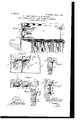
- Figure 1 is a perspective rear sectional view of a portion of a piano, illustrating the application of the invention.
- Fig. 2 is an enlarged perspective View of the improved hinge, illustrating its adaptation to the skeleton and swinging frames, showing the swinging frame more or less in wind.
- Fig. 3 is a horizontal section taken practically -on the line 3 3 of Fig. 2.
- Fig. 4 is a vertical section taken substantially on the line 4 4 of Fig. 2.
- Fig 5 is a section through a portion of the skeleton frame and a section through a portion of a hinge, illustrating a slight departure in the shape of the hinge, whereby an adjustment is accomplished by the adjustment of two screws; and
- Fig. 6 is a section similar to that shown in Fig. 4, but illustrating the adjusting action of an adjusting-screw as applied to the back face of the hinge.
- Fig. 1 illustrates the skeleton frame A of a piano, located at the back of the pilasters B, in which skeleton frame the swinging frame C operates, the latter frame being that which is adapted to support the music.
- the two frames A and C are connected by hinges D, and these hinges are located at the upper side portions of the two frames, and each hinge is in two vertical sections (Z and d, the sections (1 being secured to the skeleton frame and the section (1 to the swinging frame.
- these two sections of the hinges are in close engagement with the parts to which they are to be attached, they are secured in position by screws 10, and at the upper end of each section a sleeve 11 is formed.
- the sleeves of the sections of the hinge are made to abut when the sections are secured in position, and at the inner end of the sleeve of each section d of a hinge, or those sections which are secured to the swinging frame C, a recess 12 is produced.
- the sections 61 and d are connected by a pintle 13, which is passed through the sleeves 1 1 of the said sections, as is shown in Figsl, 2, and 3, and each pintle is provided with a lateral arm or projection 14 at its inner end, so that after a pin- 1 tle has been placed in position to connect two
- the invention consists in the novel consections of a hinge the arm 14 enters the recess 12 in the sleeve of the inner section d of parts, as will be hereinafter fully set forth,
- Fig. 1 we have shown both sections of the hinges as outwardly curved at the top from the frames to which their lower portions are firmly connected, and the said outwardlycurved upper portions are secured to the frames by screws
- the swinging frame C should be warped or in wind it can be readily straightened out by loosening sundry of the screws in certain of the sections of the hinges and tightening others, so as to bring the said swinging frame perfectly straight and in proper alinement with the inner margin of the skeleton frameas, for example, it may be possible that the swinging frame may become warped even to the extent shown in Fig. 3.
- Fig. 2 we have illustrated the section (1 of a hinge as perfectly flat andbrought by the screws 10 in close engagement with the swinging frame.
- the other section (1, which is attached to the skeleton frame, however, is out wardly curved or bent, so as to be adjustable and to bring about a suitable adjustment of the swinging frame.
- Fig. 5 a slight modification is shown, in which the section (1 of a hinge, or that section which is attached to the skeleton frame, is curved outwardly at both top and bottom and is secured in place by central screws 1.5, while other screws 16 at the top and at the bottom are likewise employed to secure this section to the said frame A; but the screws 16 are adjusting-screws, serving to draw in the hinge at the top or at the bottom, the hinge rocking on the central screw 15 as on a pivot.
- This form of hinge-section is likewise provided with a sleeve 11 at the top, and a pintle 13 is passed through the sleeve to the mating section of the hinge, which may be flat or which may be of the same character as the section d.
- Fig. 6 we have illustrated another slight departure wherein the hinge-section d, at tached to the skeleton frame A, is of the same formation. as that shown in Figs. 1, 2, and 4; but near the upper end. of the said hinge-section an opening 17 is produced, through which the working end of a screw-driver may be passed, and back of this opening 17 a screw 18 is entered into the skeleton frame, and according to the manipulation of the screw 18 the upper portion of the hinge-section will be forced outward or will be permitted to spring inward, as the hinge-section will be made of a spring material--brass or steel, for example.
- a hinge comprising a vertical section curved outwardly at its upper portion to permit of the adjustment of the said. curved portion when the hinge is in position, a second vertical section, and means for pivotally connecting the sections of the hinge together at their upper portions.
- a hinge comprising a flat section and an independent section outwardly curved at its upper portion to permit of the adjustment of the curved portion when the hinge is in position, both sections being provided with a sleeve at their upper edges, the sleeves abutting at one end when in position, and the other end of the sleeve of one section having a recess therein, and a pintle passed through the said sleeves and provided with a lateral extension at one end entering the said recess, as set forth.
- a skeleton frame and a swinging frame mounted in the skeleton frame, hinges each made in two sections, one section of a hinge being attached -to the skeleton frame and the other section to the swinging frame, both sections being provided with sleeves at their upper ends, one of the sleeves having a recess therein, the sections of the hinges secured to the skeleton frame being outwardly curved at their upper portions, means for firmly securing the lower portions of the hinges to their supports, adjustingscrews passed through the upper curved portions of the sections secured to the skeleton frame, and pintles passed through the said sleeves, having projections entering thesaid recesses so that by tightening or loosening the screws onthe curved sections of the hinges any wind in the swinging frame can be rectified, as described.
- a hinge for piano swinging frames comprising two independent sections, one of which is arranged for attachment to the skeleton frame and the other section for attachment to the swinging frame, both sections being provided with sleeves and a pintle passed through the said sleeves, the section of hinge for attachment to the skeleton frame being outwardly curved at the portion adjacent to the sleeve and adjustable toward or from the frame when in position thereon, and means for adjusting the said curved portion, as set forth.
- a skeleton frame, and a swinging frame mounted in the skeleton frame hinges each comprising a section attached to the skeleton frame and having an outwardly-curved portion and a sleeve at the end of the curved portion, another hingesec tion attached to the swinging frame and having a sleeve at one end adapted to register with the sleeve of the first-named section, and a pintle passed through the sleeves, and adjusting-screws at the said curved portion, for the purpose set forth.
Landscapes
- Engineering & Computer Science (AREA)
- Mechanical Engineering (AREA)
- Hinges (AREA)
Description
PATENTEDJANl 2, 1906. FELDER & R. K. THUMLER. GE FOR PIANO PLIOATION FILED No.s 09,o43.
LWIIII o Ma y eZEBreizfeZder INVENTORS Zara i306 2 u/nler By W ATTORNEYS U NITED STATES PATENT OFFICE.
ISRAEL E. BRETZFELDER AND ROBERT K. THUMLER, OF NEW YORK, N. Y.
REGULATING-HINGE FOR PIANO swmeme FRAMES.
Specification of Letters Patent.
Patented Jan. 2, 1906.
. Application filed May 26, 1904. Serial No. 209,883-
To ctZZ whom, it may concern:
Be it known that we, ISRAEL E. BRETZ- FELDER, a resident of the borough of Manhattan, and ROBERT K. THUMLER, a resident of the borough of the Bronx, in the city, county, and State of New York, citizens of the United States, have invented a new and improved Regulating-Hinge for Piano Swinging Frames, of which the following is a full, clear, and exact description.
The purpose of the invention is to provide a construction of hinge adapted for connecting the fixed skeleton frame of the instrument with the swinging frame or panel which supports the book or sheet of music above the keyboard, the said hinge being of such construction that the pintle may be removed when the parts of the hinge are to be separated, thus obviating the withdrawal of the screws, and wherein the pintle will remain in the position in which it is adjusted until purposely withdrawn.
other purpose of the invention is to so construct the hinge that by tightening or loosening one or the other of its members at one or the other of the sides of the parts connected by the manipulation of one or more screws of one or both sections of the hinge employed the swinging frame may be taken out of wind, or, in other words, be made to register in proper manner when closed with the marginal portions of the skeleton frame in 1 which it is adapted to operate.
struction and combination of the several and pointed out in the claims.
Reference is to be had to the accompanying drawings, forming a part of this specification, in which similar characters of reference indicate corresponding parts in all the figures.
Figure 1 is a perspective rear sectional view of a portion of a piano, illustrating the application of the invention. Fig. 2 is an enlarged perspective View of the improved hinge, illustrating its adaptation to the skeleton and swinging frames, showing the swinging frame more or less in wind. Fig. 3 is a horizontal section taken practically -on the line 3 3 of Fig. 2. Fig. 4 is a vertical section taken substantially on the line 4 4 of Fig. 2. Fig 5 is a section through a portion of the skeleton frame and a section through a portion of a hinge, illustrating a slight departure in the shape of the hinge, whereby an adjustment is accomplished by the adjustment of two screws; and Fig. 6 is a section similar to that shown in Fig. 4, but illustrating the adjusting action of an adjusting-screw as applied to the back face of the hinge.
Fig. 1 illustrates the skeleton frame A of a piano, located at the back of the pilasters B, in which skeleton frame the swinging frame C operates, the latter frame being that which is adapted to support the music. The two frames A and C are connected by hinges D, and these hinges are located at the upper side portions of the two frames, and each hinge is in two vertical sections (Z and d, the sections (1 being secured to the skeleton frame and the section (1 to the swinging frame. When these two sections of the hinges are in close engagement with the parts to which they are to be attached, they are secured in position by screws 10, and at the upper end of each section a sleeve 11 is formed. The sleeves of the sections of the hinge are made to abut when the sections are secured in position, and at the inner end of the sleeve of each section d of a hinge, or those sections which are secured to the swinging frame C, a recess 12 is produced. The sections 61 and d are connected by a pintle 13, which is passed through the sleeves 1 1 of the said sections, as is shown in Figsl, 2, and 3, and each pintle is provided with a lateral arm or projection 14 at its inner end, so that after a pin- 1 tle has been placed in position to connect two The invention consists in the novel consections of a hinge the arm 14 enters the recess 12 in the sleeve of the inner section d of parts, as will be hereinafter fully set forth,
a hinge, and thus the pintle is held in proper position until it is purposely removed, and upon removing the pintles from the hinges the sections of said hinges are disconnected, and the swinging frame can then be taken out from the skeleton frame without trouble and can be quickly replaced and held in position by simply restoring the pintles to their normal or working position.
In Fig. 1 we have shown both sections of the hinges as outwardly curved at the top from the frames to which their lower portions are firmly connected, and the said outwardlycurved upper portions are secured to the frames by screws Thus if the swinging frame C should be warped or in wind it can be readily straightened out by loosening sundry of the screws in certain of the sections of the hinges and tightening others, so as to bring the said swinging frame perfectly straight and in proper alinement with the inner margin of the skeleton frameas, for example, it may be possible that the swinging frame may become warped even to the extent shown in Fig. 3.
In Fig. 2 we have illustrated the section (1 of a hinge as perfectly flat andbrought by the screws 10 in close engagement with the swinging frame. The other section (1, which is attached to the skeleton frame, however, is out wardly curved or bent, so as to be adjustable and to bring about a suitable adjustment of the swinging frame.
In Fig. 5 a slight modification is shown, in which the section (1 of a hinge, or that section which is attached to the skeleton frame, is curved outwardly at both top and bottom and is secured in place by central screws 1.5, while other screws 16 at the top and at the bottom are likewise employed to secure this section to the said frame A; but the screws 16 are adjusting-screws, serving to draw in the hinge at the top or at the bottom, the hinge rocking on the central screw 15 as on a pivot. This form of hinge-section is likewise provided with a sleeve 11 at the top, and a pintle 13 is passed through the sleeve to the mating section of the hinge, which may be flat or which may be of the same character as the section d.
In Fig. 6 we have illustrated another slight departure wherein the hinge-section d, at tached to the skeleton frame A, is of the same formation. as that shown in Figs. 1, 2, and 4; but near the upper end. of the said hinge-section an opening 17 is produced, through which the working end of a screw-driver may be passed, and back of this opening 17 a screw 18 is entered into the skeleton frame, and according to the manipulation of the screw 18 the upper portion of the hinge-section will be forced outward or will be permitted to spring inward, as the hinge-section will be made of a spring material--brass or steel, for example.
It is evident from the foregoing description that not only can the swinging frame be quickly and conveniently applied to the skeleton frame or disconnected therefrom, but likewise with equal rapidity and convenience any wind, twist, or shrinkage in the swinging frame, which would render it untrue in position, can be rectified by the manipulation of the adjusting-screws of the hinges.
Having thus described our invention, we claim as new and desire to secure by Letters Patent 1. A hinge comprising a vertical section curved outwardly at its upper portion to permit of the adjustment of the said. curved portion when the hinge is in position, a second vertical section, and means for pivotally connecting the sections of the hinge together at their upper portions.
2. A hinge, comprising a flat section and an independent section outwardly curved at its upper portion to permit of the adjustment of the curved portion when the hinge is in position, both sections being provided with a sleeve at their upper edges, the sleeves abutting at one end when in position, and the other end of the sleeve of one section having a recess therein, and a pintle passed through the said sleeves and provided with a lateral extension at one end entering the said recess, as set forth.
3. In pianos, a skeleton frame and a swinging frame mounted in the skeleton frame, hinges each made in two sections, one section of a hinge being attached -to the skeleton frame and the other section to the swinging frame, both sections being provided with sleeves at their upper ends, one of the sleeves having a recess therein, the sections of the hinges secured to the skeleton frame being outwardly curved at their upper portions, means for firmly securing the lower portions of the hinges to their supports, adjustingscrews passed through the upper curved portions of the sections secured to the skeleton frame, and pintles passed through the said sleeves, having projections entering thesaid recesses so that by tightening or loosening the screws onthe curved sections of the hinges any wind in the swinging frame can be rectified, as described.
4. A hinge for piano swinging frames comprising two independent sections, one of which is arranged for attachment to the skeleton frame and the other section for attachment to the swinging frame, both sections being provided with sleeves and a pintle passed through the said sleeves, the section of hinge for attachment to the skeleton frame being outwardly curved at the portion adjacent to the sleeve and adjustable toward or from the frame when in position thereon, and means for adjusting the said curved portion, as set forth.
5. In pianos and the like, a skeleton frame, and a swinging frame mounted in the skeleton frame, hinges each comprising a section attached to the skeleton frame and having an outwardly-curved portion and a sleeve at the end of the curved portion, another hingesec tion attached to the swinging frame and having a sleeve at one end adapted to register with the sleeve of the first-named section, and a pintle passed through the sleeves, and adjusting-screws at the said curved portion, for the purpose set forth.
In testimony whereof we have signed our names to this specification in the presence of two subscribing witnesses.
ISRAEL E. BRETZFELDER. ROBERT K. THUMLER.
I/Vitnesses MAURICE F. GATzsoH, JOSEPH F. SMITH.
Priority Applications (1)
| Application Number | Priority Date | Filing Date | Title |
|---|---|---|---|
| US20988304A US809043A (en) | 1904-05-26 | 1904-05-26 | Regulating-hinge for piano swinging frames. |
Applications Claiming Priority (1)
| Application Number | Priority Date | Filing Date | Title |
|---|---|---|---|
| US20988304A US809043A (en) | 1904-05-26 | 1904-05-26 | Regulating-hinge for piano swinging frames. |
Publications (1)
| Publication Number | Publication Date |
|---|---|
| US809043A true US809043A (en) | 1906-01-02 |
Family
ID=2877524
Family Applications (1)
| Application Number | Title | Priority Date | Filing Date |
|---|---|---|---|
| US20988304A Expired - Lifetime US809043A (en) | 1904-05-26 | 1904-05-26 | Regulating-hinge for piano swinging frames. |
Country Status (1)
| Country | Link |
|---|---|
| US (1) | US809043A (en) |
Cited By (2)
| Publication number | Priority date | Publication date | Assignee | Title |
|---|---|---|---|---|
| US2867838A (en) * | 1955-07-19 | 1959-01-13 | Carl T Nielsen | Adjustable hinge |
| US2940115A (en) * | 1956-10-11 | 1960-06-14 | Hansen Hans Ulrik | Adjustable door hinge |
-
1904
- 1904-05-26 US US20988304A patent/US809043A/en not_active Expired - Lifetime
Cited By (2)
| Publication number | Priority date | Publication date | Assignee | Title |
|---|---|---|---|---|
| US2867838A (en) * | 1955-07-19 | 1959-01-13 | Carl T Nielsen | Adjustable hinge |
| US2940115A (en) * | 1956-10-11 | 1960-06-14 | Hansen Hans Ulrik | Adjustable door hinge |
Similar Documents
| Publication | Publication Date | Title |
|---|---|---|
| US809043A (en) | Regulating-hinge for piano swinging frames. | |
| US664181A (en) | Drawer-pull. | |
| US532044A (en) | Adjustable hinge | |
| US639031A (en) | Index. | |
| US719640A (en) | Hinge. | |
| US861722A (en) | Knee-board and copy-holder. | |
| US1105186A (en) | Safety-sleeve for hinges and the like. | |
| US665706A (en) | Temporary binder. | |
| US819847A (en) | Educational appliance. | |
| US396508A (en) | Cover for writing-tablets | |
| US1036073A (en) | Photo printing apparatus. | |
| US94807A (en) | Improvement in printers copy-holders | |
| US334933A (en) | Stephax bbambach | |
| US115053A (en) | Improvement in front-falls for pianos | |
| US1140271A (en) | Governor-spring. | |
| US634474A (en) | Pianoforte-flange. | |
| USD3354S (en) | Design for a hinge | |
| US758639A (en) | Piano construction. | |
| US1116148A (en) | Door-hinge. | |
| US472588A (en) | Piano-forte | |
| US601241A (en) | Fastening device for hinges | |
| US643749A (en) | Telephone-directory. | |
| US114582A (en) | Improvement in paper boxes | |
| US824923A (en) | Spring-hinge. | |
| US209761A (en) | Improvement in hand-rests |