US8053999B2 - HID ballast - Google Patents
HID ballast Download PDFInfo
- Publication number
- US8053999B2 US8053999B2 US11/793,248 US79324805A US8053999B2 US 8053999 B2 US8053999 B2 US 8053999B2 US 79324805 A US79324805 A US 79324805A US 8053999 B2 US8053999 B2 US 8053999B2
- Authority
- US
- United States
- Prior art keywords
- switching
- lamp
- control apparatus
- power control
- elements
- Prior art date
- Legal status (The legal status is an assumption and is not a legal conclusion. Google has not performed a legal analysis and makes no representation as to the accuracy of the status listed.)
- Expired - Fee Related
Links
Images


Classifications
-
- H—ELECTRICITY
- H05—ELECTRIC TECHNIQUES NOT OTHERWISE PROVIDED FOR
- H05B—ELECTRIC HEATING; ELECTRIC LIGHT SOURCES NOT OTHERWISE PROVIDED FOR; CIRCUIT ARRANGEMENTS FOR ELECTRIC LIGHT SOURCES, IN GENERAL
- H05B41/00—Circuit arrangements or apparatus for igniting or operating discharge lamps
- H05B41/14—Circuit arrangements
- H05B41/26—Circuit arrangements in which the lamp is fed by power derived from dc by means of a converter, e.g. by high-voltage dc
- H05B41/28—Circuit arrangements in which the lamp is fed by power derived from dc by means of a converter, e.g. by high-voltage dc using static converters
- H05B41/288—Circuit arrangements in which the lamp is fed by power derived from dc by means of a converter, e.g. by high-voltage dc using static converters with semiconductor devices and specially adapted for lamps without preheating electrodes, e.g. for high-intensity discharge lamps, high-pressure mercury or sodium lamps or low-pressure sodium lamps
- H05B41/2881—Load circuits; Control thereof
- H05B41/2882—Load circuits; Control thereof the control resulting from an action on the static converter
-
- H—ELECTRICITY
- H05—ELECTRIC TECHNIQUES NOT OTHERWISE PROVIDED FOR
- H05B—ELECTRIC HEATING; ELECTRIC LIGHT SOURCES NOT OTHERWISE PROVIDED FOR; CIRCUIT ARRANGEMENTS FOR ELECTRIC LIGHT SOURCES, IN GENERAL
- H05B41/00—Circuit arrangements or apparatus for igniting or operating discharge lamps
- H05B41/14—Circuit arrangements
- H05B41/24—Circuit arrangements in which the lamp is fed by high frequency ac, or with separate oscillator frequency
-
- H—ELECTRICITY
- H05—ELECTRIC TECHNIQUES NOT OTHERWISE PROVIDED FOR
- H05B—ELECTRIC HEATING; ELECTRIC LIGHT SOURCES NOT OTHERWISE PROVIDED FOR; CIRCUIT ARRANGEMENTS FOR ELECTRIC LIGHT SOURCES, IN GENERAL
- H05B41/00—Circuit arrangements or apparatus for igniting or operating discharge lamps
- H05B41/14—Circuit arrangements
- H05B41/26—Circuit arrangements in which the lamp is fed by power derived from dc by means of a converter, e.g. by high-voltage dc
- H05B41/28—Circuit arrangements in which the lamp is fed by power derived from dc by means of a converter, e.g. by high-voltage dc using static converters
- H05B41/288—Circuit arrangements in which the lamp is fed by power derived from dc by means of a converter, e.g. by high-voltage dc using static converters with semiconductor devices and specially adapted for lamps without preheating electrodes, e.g. for high-intensity discharge lamps, high-pressure mercury or sodium lamps or low-pressure sodium lamps
- H05B41/2885—Static converters especially adapted therefor; Control thereof
- H05B41/2887—Static converters especially adapted therefor; Control thereof characterised by a controllable bridge in the final stage
-
- Y—GENERAL TAGGING OF NEW TECHNOLOGICAL DEVELOPMENTS; GENERAL TAGGING OF CROSS-SECTIONAL TECHNOLOGIES SPANNING OVER SEVERAL SECTIONS OF THE IPC; TECHNICAL SUBJECTS COVERED BY FORMER USPC CROSS-REFERENCE ART COLLECTIONS [XRACs] AND DIGESTS
- Y02—TECHNOLOGIES OR APPLICATIONS FOR MITIGATION OR ADAPTATION AGAINST CLIMATE CHANGE
- Y02B—CLIMATE CHANGE MITIGATION TECHNOLOGIES RELATED TO BUILDINGS, e.g. HOUSING, HOUSE APPLIANCES OR RELATED END-USER APPLICATIONS
- Y02B20/00—Energy efficient lighting technologies, e.g. halogen lamps or gas discharge lamps
Definitions
- the present invention relates to power control apparatus for providing electric power from a utility to desired voltage and current characteristics for a load.
- the present invention relates to a method and apparatus for providing current to a high intensity discharge lamp via a lamp ballast with reduced power loss.
- a load There are many known circumstances when power should be provided to a load. Under such circumstances the power supplied to a load must be strictly controlled so that thresholds in that load are met but not exceeded.
- a load is a lamp. High intensity discharge lamp are one variety of lamp.
- High intensity discharge (HID) lamps have been available for a number of years and consist of a sealed, usually double envelope inside which a plasma discharge takes place.
- the discharge ionises the gas which will emit light at various wavelengths depending on the composition of the gas within the discharge envelope.
- a full bridge circuit is used for a dual purpose to generate a high frequency resonant voltage to strike the lamp and a low frequency, controlled current during the run condition.
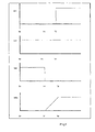
- Q 3 and Q 4 are turned on and off at a suitable low frequency such that when Q 3 is on Q 4 is off and visa versa. If Q 3 is on then Q 1 is off always off and similarly if Q 4 is on then Q 2 is always off. Assuming that Q 3 is on, then Q 2 is alternately turned on and off (Pulse Width Modulated PWM) at a higher frequency than Q 3 and Q 4 to control the current through the load. As any current flowing in L 1 will be flowing in D 1 before Q 2 turns on, then Q 2 has to commutate this current before the voltage on D 2 cathode falls to zero. The sequence of Q 2 turning on is shown in the waveforms of FIG. 3 .
- the bridge circuit can be supplied from any of a number of well known electronic pfc stages that give a suitable stable high voltage rail.
- power control apparatus for providing current to a load, comprising:
- a full/half bridge switching circuit including at least one switching element for supplying power to a load when switched on;
- a method for providing current in a load comprising the steps of:
- a power control apparatus including a full/half bridge switching circuit
- Embodiments of the present invention provide the advantage that the switching elements in lamp ballast circuitry are switched only under a zero voltage condition so that power dissipated is reduced compared to prior art ballast.
- FIG. 1 illustrates a prior art ballast
- FIG. 2 illustrates another prior art ballast
- FIG. 3 illustrates the response of parts of the prior art circuit
- FIG. 4 illustrates the response at parts of the prior art circuitry
- FIG. 5 illustrates a lamp ballast according to an embodiment of the present invention
- FIG. 6 illustrates timings and development of other parameters
- FIG. 7 illustrates the development of certain parameters in the circuit of FIG. 5 .
- the invention combines the functions of a current source with zero voltage switching (ZVS) whilst preserving the resonant strike function into one full bridge power conversion stage, reducing power losses, ripple current in the lamp, EMI and improving efficiency.
- ZVS zero voltage switching
- the switches Q 1 - 4 are shown as bipolar devices but could equally be mos-fets or any other type of electronic switch.
- the diode D 1 and capacitor C 3 could be part of the switch Q 1 or separate. If C 3 is part of the switching element it may be augmented by additional capacitance in parallel.
- Q 2 , D 2 , C 4 and Q 3 , Q 4 and D 3 , D 4 may be augmented by additional capacitance in parallel.
- Q 3 and Q 4 are turned on alternately at a low frequency.
- Q 3 is on Q 4 is off and visa versa.
- Q 2 is turned on and off by pulse width modulation (PWM) using ZVS in such a way as to maintain the current in the lamp substantially constant.
- PWM pulse width modulation
- Q 1 is turned off for all the time that Q 3 is on in this mode.
- the value of C 2 is such that its voltage does not change substantially during the time that it takes for Q 2 to turn on or off.
- the ZVS action is described as follows with reference to the waveforms in FIG. 6 and FIG. 7 .
- Q 1 When Q 3 turns off and Q 4 turns on then Q 1 is turned on and off in the same manner as was Q 2 and Q 2 is turned off for all the time that Q 4 is on. In this way Q 1 and Q 2 are turned on and off with substantially zero volts across them and so have minimal switching losses. It is clear that the rate at which the voltage changes across the switches is determined by C 3 , C 4 and L 2 and so can be optimised by changing these values for EMI and/or power loss.
- the circuit of FIG. 5 contains an extra LC filter stage compared to the prior art and as such leads to reduced current ripple in the lamp and reduces the chances of acoustic arc resonance caused by such excessive ripple currents.
- Q 3 and Q 4 may be driven at high frequency either on their own or in conjunction with Q 1 and Q 2 to cause L 1 /C 1 to resonate and generate the high voltage to start the lamp.
- Embodiments of the present invention have been described in which the status, that is whether a switch is on or off, is changed only at a point in time when the voltage across a switching element is substantially zero or much reduced. In this way power dissipated by the device is controlled.
Landscapes
- Circuit Arrangements For Discharge Lamps (AREA)
Applications Claiming Priority (3)
| Application Number | Priority Date | Filing Date | Title |
|---|---|---|---|
| GB0427682A GB0427682D0 (en) | 2004-12-17 | 2004-12-17 | Power control |
| GB0427682.0 | 2004-12-17 | ||
| PCT/GB2005/004611 WO2006064182A1 (en) | 2004-12-17 | 2005-12-02 | Hid ballast |
Publications (2)
| Publication Number | Publication Date |
|---|---|
| US20080252228A1 US20080252228A1 (en) | 2008-10-16 |
| US8053999B2 true US8053999B2 (en) | 2011-11-08 |
Family
ID=34090237
Family Applications (1)
| Application Number | Title | Priority Date | Filing Date |
|---|---|---|---|
| US11/793,248 Expired - Fee Related US8053999B2 (en) | 2004-12-17 | 2005-12-02 | HID ballast |
Country Status (9)
| Country | Link |
|---|---|
| US (1) | US8053999B2 (ja) |
| EP (1) | EP1829434B1 (ja) |
| JP (1) | JP2008524787A (ja) |
| KR (1) | KR20070101858A (ja) |
| CN (1) | CN101116379B (ja) |
| AU (1) | AU2005315423B2 (ja) |
| CA (1) | CA2590915A1 (ja) |
| GB (1) | GB0427682D0 (ja) |
| WO (1) | WO2006064182A1 (ja) |
Cited By (3)
| Publication number | Priority date | Publication date | Assignee | Title |
|---|---|---|---|---|
| US20110169427A1 (en) * | 2008-09-17 | 2011-07-14 | Osram Gesellschaft Mit Beschraenkter Haftung | Circuit arrangement and method for operation of a discharge lamp |
| US20120274237A1 (en) * | 2009-11-02 | 2012-11-01 | Chung Henry Shu Hung | Apparatus or circuit for driving a dc powered lighting equipment |
| US20150061518A1 (en) * | 2013-08-30 | 2015-03-05 | Lextar Electronics Corporation | Light adjusting device with switching element |
Families Citing this family (1)
| Publication number | Priority date | Publication date | Assignee | Title |
|---|---|---|---|---|
| CN102612238B (zh) * | 2012-03-26 | 2015-01-14 | 上海信耀电子有限公司 | 基于dsp的hid镇流器 |
Citations (20)
| Publication number | Priority date | Publication date | Assignee | Title |
|---|---|---|---|---|
| US4725762A (en) | 1985-02-04 | 1988-02-16 | Zumtobel Aktiengesellschaft | Circuit supplied with direct voltage for generating voltages and/or currents with different curve form and/or different frequency and/or different polarity with at least one load |
| US5371440A (en) | 1993-12-28 | 1994-12-06 | Philips Electronics North America Corp. | High frequency miniature electronic ballast with low RFI |
| US5434479A (en) * | 1992-09-22 | 1995-07-18 | Matsushita Electric Works, Ltd. | Full-bridge inverter for discharge lamp lighting device with varied transistor zero voltage period |
| DE19523750A1 (de) | 1995-06-29 | 1997-01-02 | Thomson Brandt Gmbh | Wechselstromquelle |
| US5844374A (en) * | 1996-05-23 | 1998-12-01 | U.S. Philips Corporation | Inverter arrangement employing resonant capacitive elements directly connected across the switching elements for zero voltage switching |
| US5962981A (en) * | 1997-04-18 | 1999-10-05 | Matsushita Electric Works, Ltd. | Discharge lamp lighting device |
| US6020691A (en) | 1999-04-30 | 2000-02-01 | Matsushita Electric Works R & D Laboratory, Inc. | Driving circuit for high intensity discharge lamp electronic ballast |
| US6124682A (en) | 1996-11-19 | 2000-09-26 | Micro Tech Limited | Lamp driver circuit using resonant circuit for starting lamp |
| US20010002781A1 (en) * | 1999-12-03 | 2001-06-07 | Kim Joong S. | Electronic ballast for gas discharge lamp |
| US20020030451A1 (en) * | 2000-02-25 | 2002-03-14 | Moisin Mihail S. | Ballast circuit having voltage clamping circuit |
| US6380694B1 (en) | 2000-09-22 | 2002-04-30 | Matsushita Electric Works R & D Laboratory | Variable structure circuit topology for HID lamp electronic ballasts |
| US6426597B2 (en) * | 1998-09-18 | 2002-07-30 | Knobel Ag Lichttechnische Komponenten | Circuit arrangement for operating gas discharge lamps |
| US20030025466A1 (en) * | 1999-12-27 | 2003-02-06 | Tridoniatco Gmbh & Co. Kg | Circuit configuration to operate a gas discharge lamp |
| US20030102818A1 (en) * | 2001-12-05 | 2003-06-05 | Koninklijke Philips Electronics N.V. | High power factor electronic ballast with lossless switching |
| US20040007992A1 (en) | 2002-07-09 | 2004-01-15 | International Rectifier Corporation | Adaptive ballast control IC |
| US20040070352A1 (en) * | 2001-08-15 | 2004-04-15 | Koninklijke Philips Electronics N.V. | Method for color mixing with arc stability and straightening of HID lamps operated at high frequencies using duty cycle modulation |
| JP2004260882A (ja) | 2003-02-24 | 2004-09-16 | Sanken Electric Co Ltd | 電力変換装置 |
| US20050041439A1 (en) | 2003-08-21 | 2005-02-24 | Delta Electronics, Inc. | Full bridge power converters with zero-voltage switching |
| US20060049777A1 (en) * | 2002-10-28 | 2006-03-09 | Jun Kumagai | High-pressure discharge lamp operation device and illumination appliance having the same |
| US7061187B2 (en) * | 2003-03-19 | 2006-06-13 | Moisin Mihail S | Circuit having clamped global feedback for linear load current |
-
2004
- 2004-12-17 GB GB0427682A patent/GB0427682D0/en not_active Ceased
-
2005
- 2005-12-02 EP EP20050818367 patent/EP1829434B1/en not_active Revoked
- 2005-12-02 CN CN2005800480737A patent/CN101116379B/zh not_active Expired - Fee Related
- 2005-12-02 CA CA 2590915 patent/CA2590915A1/en not_active Abandoned
- 2005-12-02 WO PCT/GB2005/004611 patent/WO2006064182A1/en active Application Filing
- 2005-12-02 US US11/793,248 patent/US8053999B2/en not_active Expired - Fee Related
- 2005-12-02 KR KR1020077015700A patent/KR20070101858A/ko not_active Application Discontinuation
- 2005-12-02 AU AU2005315423A patent/AU2005315423B2/en not_active Ceased
- 2005-12-02 JP JP2007546158A patent/JP2008524787A/ja active Pending
Patent Citations (21)
| Publication number | Priority date | Publication date | Assignee | Title |
|---|---|---|---|---|
| US4725762A (en) | 1985-02-04 | 1988-02-16 | Zumtobel Aktiengesellschaft | Circuit supplied with direct voltage for generating voltages and/or currents with different curve form and/or different frequency and/or different polarity with at least one load |
| US5434479A (en) * | 1992-09-22 | 1995-07-18 | Matsushita Electric Works, Ltd. | Full-bridge inverter for discharge lamp lighting device with varied transistor zero voltage period |
| US5371440A (en) | 1993-12-28 | 1994-12-06 | Philips Electronics North America Corp. | High frequency miniature electronic ballast with low RFI |
| DE19523750A1 (de) | 1995-06-29 | 1997-01-02 | Thomson Brandt Gmbh | Wechselstromquelle |
| US5844374A (en) * | 1996-05-23 | 1998-12-01 | U.S. Philips Corporation | Inverter arrangement employing resonant capacitive elements directly connected across the switching elements for zero voltage switching |
| US6124682A (en) | 1996-11-19 | 2000-09-26 | Micro Tech Limited | Lamp driver circuit using resonant circuit for starting lamp |
| US5962981A (en) * | 1997-04-18 | 1999-10-05 | Matsushita Electric Works, Ltd. | Discharge lamp lighting device |
| US6426597B2 (en) * | 1998-09-18 | 2002-07-30 | Knobel Ag Lichttechnische Komponenten | Circuit arrangement for operating gas discharge lamps |
| US6020691A (en) | 1999-04-30 | 2000-02-01 | Matsushita Electric Works R & D Laboratory, Inc. | Driving circuit for high intensity discharge lamp electronic ballast |
| US20010002781A1 (en) * | 1999-12-03 | 2001-06-07 | Kim Joong S. | Electronic ballast for gas discharge lamp |
| US20030025466A1 (en) * | 1999-12-27 | 2003-02-06 | Tridoniatco Gmbh & Co. Kg | Circuit configuration to operate a gas discharge lamp |
| US20020030451A1 (en) * | 2000-02-25 | 2002-03-14 | Moisin Mihail S. | Ballast circuit having voltage clamping circuit |
| US6380694B1 (en) | 2000-09-22 | 2002-04-30 | Matsushita Electric Works R & D Laboratory | Variable structure circuit topology for HID lamp electronic ballasts |
| JP2002151286A (ja) | 2000-09-22 | 2002-05-24 | Matsushita Electric Works Ltd | 高輝度放電ランプの駆動回路 |
| US20040070352A1 (en) * | 2001-08-15 | 2004-04-15 | Koninklijke Philips Electronics N.V. | Method for color mixing with arc stability and straightening of HID lamps operated at high frequencies using duty cycle modulation |
| US20030102818A1 (en) * | 2001-12-05 | 2003-06-05 | Koninklijke Philips Electronics N.V. | High power factor electronic ballast with lossless switching |
| US20040007992A1 (en) | 2002-07-09 | 2004-01-15 | International Rectifier Corporation | Adaptive ballast control IC |
| US20060049777A1 (en) * | 2002-10-28 | 2006-03-09 | Jun Kumagai | High-pressure discharge lamp operation device and illumination appliance having the same |
| JP2004260882A (ja) | 2003-02-24 | 2004-09-16 | Sanken Electric Co Ltd | 電力変換装置 |
| US7061187B2 (en) * | 2003-03-19 | 2006-06-13 | Moisin Mihail S | Circuit having clamped global feedback for linear load current |
| US20050041439A1 (en) | 2003-08-21 | 2005-02-24 | Delta Electronics, Inc. | Full bridge power converters with zero-voltage switching |
Non-Patent Citations (3)
| Title |
|---|
| International Search Report and Written Opinion of the International Searching Authority for corresponding PCT Application No. PCT/GB2005/004611. |
| Japanese Patent Office, "Decision of Rejection" for corresponding Japanese Patent Application No. 2007-546158, Jun. 21, 2011, 6 pages. |
| Redl, et al., "Optimum ZVS Full-Bridge DC/DC Converter with PWM Phase-Shift Control: Analysis, Design Considerations, and Experimental results," Applied Power Electronics Conference and Exposition, Conference Proceedings, pp. 159-165, 1994. |
Cited By (6)
| Publication number | Priority date | Publication date | Assignee | Title |
|---|---|---|---|---|
| US20110169427A1 (en) * | 2008-09-17 | 2011-07-14 | Osram Gesellschaft Mit Beschraenkter Haftung | Circuit arrangement and method for operation of a discharge lamp |
| US8531122B2 (en) * | 2008-09-17 | 2013-09-10 | Osram Gesellschaft Mit Beschraenkter Haftung | Circuit arrangement and method for operation of a discharge lamp |
| US20120274237A1 (en) * | 2009-11-02 | 2012-11-01 | Chung Henry Shu Hung | Apparatus or circuit for driving a dc powered lighting equipment |
| US9714759B2 (en) * | 2009-11-02 | 2017-07-25 | City University Of Hong Kong | Apparatus or circuit for driving a DC powered lighting equipment |
| US20150061518A1 (en) * | 2013-08-30 | 2015-03-05 | Lextar Electronics Corporation | Light adjusting device with switching element |
| US9089022B2 (en) * | 2013-08-30 | 2015-07-21 | Lextar Electronics Corporation | Light adjusting device with switching element |
Also Published As
| Publication number | Publication date |
|---|---|
| US20080252228A1 (en) | 2008-10-16 |
| CA2590915A1 (en) | 2006-06-22 |
| JP2008524787A (ja) | 2008-07-10 |
| CN101116379A (zh) | 2008-01-30 |
| WO2006064182A1 (en) | 2006-06-22 |
| EP1829434B1 (en) | 2014-01-29 |
| GB0427682D0 (en) | 2005-01-19 |
| CN101116379B (zh) | 2011-04-13 |
| KR20070101858A (ko) | 2007-10-17 |
| AU2005315423A1 (en) | 2006-06-22 |
| EP1829434A1 (en) | 2007-09-05 |
| AU2005315423B2 (en) | 2012-01-19 |
Similar Documents
| Publication | Publication Date | Title |
|---|---|---|
| US6380694B1 (en) | Variable structure circuit topology for HID lamp electronic ballasts | |
| CA2224300C (en) | Discharge lamp driving bridge circuit | |
| US6188183B1 (en) | High intensity discharge lamp ballast | |
| US7061188B1 (en) | Instant start electronic ballast with universal AC input voltage | |
| EP1332646B1 (en) | Electronic ballast with continued conduction of line current | |
| US6495971B1 (en) | High intensity discharge lamp ballast | |
| EP1330943B1 (en) | Ballast self oscillating inverter with phase controlled voltage feedback | |
| US7164239B2 (en) | Discharge lamp ballast circuit | |
| US8053999B2 (en) | HID ballast | |
| KR101391202B1 (ko) | 전압 트랜스포머를 포함하는 회로 어레인지먼트 및 연관된 방법 | |
| CN101518158B (zh) | 用于向高强度放电灯供电的电路 | |
| US20070145905A1 (en) | Driver device for a gas discharge lamp and igniter | |
| JP3758305B2 (ja) | 照明用点灯装置 | |
| JP2005051845A (ja) | Dc−dcコンバータおよびそれを用いた高圧放電ランプ点灯装置 | |
| US20070164685A1 (en) | Discharge lamp lighting apparatus | |
| JP3671243B2 (ja) | 共振型電力変換装置 | |
| JPH11233279A (ja) | 照明用点灯装置及びこれを用いたランプ | |
| KR100312114B1 (ko) | 필라멘트 예열기능을 가진 고역률 형광등용 전자식 안정기 | |
| KR20030075414A (ko) | 형광램프용 전자식 안정기 회로 | |
| Krizhanovski et al. | Low-voltage self-oscillating class E electronic ballast for fluorescent lamps | |
| JP3518230B2 (ja) | 点灯装置 | |
| JP2000188872A (ja) | インバータ装置 | |
| KR20170103191A (ko) | 풀 브릿지 인버터 방식의 고압 방전등용 전자식 안정기 | |
| JPH04137498A (ja) | 放電灯点灯装置 | |
| JP2000125566A (ja) | 点灯装置 |
Legal Events
| Date | Code | Title | Description |
|---|---|---|---|
| AS | Assignment |
Owner name: HARVARD ENGINEERING PLC, UNITED KINGDOM Free format text: ASSIGNMENT OF ASSIGNORS INTEREST;ASSIGNOR:SMETHURST, CHRISTOPHER JOHN;REEL/FRAME:020160/0158 Effective date: 20071017 |
|
| REMI | Maintenance fee reminder mailed | ||
| LAPS | Lapse for failure to pay maintenance fees | ||
| STCH | Information on status: patent discontinuation |
Free format text: PATENT EXPIRED DUE TO NONPAYMENT OF MAINTENANCE FEES UNDER 37 CFR 1.362 |
|
| FP | Lapsed due to failure to pay maintenance fee |
Effective date: 20151108 |