US8041063B2 - Hearing aid and hearing aid system - Google Patents
Hearing aid and hearing aid system Download PDFInfo
- Publication number
- US8041063B2 US8041063B2 US13/059,875 US200913059875A US8041063B2 US 8041063 B2 US8041063 B2 US 8041063B2 US 200913059875 A US200913059875 A US 200913059875A US 8041063 B2 US8041063 B2 US 8041063B2
- Authority
- US
- United States
- Prior art keywords
- hearing aid
- sound
- setting
- signal
- input signal
- Prior art date
- Legal status (The legal status is an assumption and is not a legal conclusion. Google has not performed a legal analysis and makes no representation as to the accuracy of the status listed.)
- Expired - Fee Related
Links
Images


Classifications
-
- H—ELECTRICITY
- H04—ELECTRIC COMMUNICATION TECHNIQUE
- H04R—LOUDSPEAKERS, MICROPHONES, GRAMOPHONE PICK-UPS OR LIKE ACOUSTIC ELECTROMECHANICAL TRANSDUCERS; DEAF-AID SETS; PUBLIC ADDRESS SYSTEMS
- H04R25/00—Deaf-aid sets, i.e. electro-acoustic or electro-mechanical hearing aids; Electric tinnitus maskers providing an auditory perception
- H04R25/70—Adaptation of deaf aid to hearing loss, e.g. initial electronic fitting
Definitions
- This invention relates to a hearing aid and a hearing aid system and in particular to a hearing aid and a hearing aid system capable of simplifying setting (volume and operation mode) change of the hearing aid.
- a hearing aid to improve the audibility of sound, etc., in response to distinguishing between sound and non-sound and the degree of surrounding noise, undesired sound, or reverberation and play high-clarity sound independently of the sound environment.
- a hearing aid including a hearing aid main body to which a volume change button and an operation mode change button are added for enabling a person wearing the hearing aid to consciously change setting in response to the use scene and the sound environment (for example, see Patent Document 1).
- FIG. 12 is a block diagram to show a configuration example of such a remote control hearing aid system.
- This remote control hearing aid system includes a telephone 10 and a hearing aid 40 .
- a call detection unit 6 of the telephone 10 detects the call.
- a control signal generation unit 5 generates a control signal.
- the control signal and a receiving signal are converted into an acoustic signal by an electroacoustic transducer 4 and the acoustic signal is transmitted to the hearing aid 40 .
- the transmitted acoustic signal is received by a sound wave reception unit 41 of the hearing aid 40 and is converted into reception signal of an electric signal.
- the reception signal provided by the sound wave reception unit 41 is sent through a reception switch unit 43 to a power amplification unit 44 and an analysis control unit 46 .
- the sent reception signal is subjected to frequency analysis and is compared with a stored signal in the analysis control unit 46 , whereby a control signal is generated.
- the control signal is sent to the power amplification unit 44 and is used to change the amplification factor of the reception signal (for example, see Patent Document 4).
- the conventional hearing aid described above involves a problem in that when the user consciously changes setting of the hearing aid main body, the volume change button and the operation mode change button are small and the user cannot directly see the buttons at the hearing aid wearing time and it is difficult for the user to change the setting.
- the technique of automatically changing setting of the hearing aid in response to the sound environment has the advantage that operation is not required, but involves a problem in that intention of the user and the setting do not necessarily match.
- the technique of changing setting with a different device other than the hearing aid main body has the constraint that the user cannot change setting as intended unless the user always carries the separated device.
- the acoustic parameter is adjusted using external devices of the server, the database, the telephone, etc., and in order to adjust the acoustic parameter using the external devices, the user hears a dissonant adjustment sound at the setting time with a mobile telephone and feels his or her displeasure.
- an object of the invention is to provide a hearing aid and a hearing aid system which can reflect setting change of the hearing aid responsive to a sound environment by the user as he or she intends, which can prevent the user from feeling his or her inconvenience or displeasure caused by changing setting of the hearing aid, and which can allow the user to easily change the setting.
- a hearing aid of the invention comprises: a microphone configured to generate an input signal from an input sound; a signal processing unit configured to generate an output signal from the input signal; and a receiver configured to play an output sound from the output signal, wherein the signal processing unit determines a time response of the input signal based on a contact sound generated when the hearing aid is contacted in a predetermined time period, and changes setting of the hearing aid based on the time response.
- the time response of the input signal is determined and setting of the hearing aid is changed based on the time response, so that setting of the hearing aid (acoustic parameters of volume, operation mode, etc.,) can be easily changed without performing button operation of a miniaturized hearing aid and by only using the hearing aid without using another device.
- the signal processing unit calculates an intensity of the input signal, and changes the setting of the hearing aid when the signal processing unit detects at least two time points, each at which an average value of the intensity of the input signal in a predetermined time period is equal to or less than a first predetermined threshold value and also at which the intensity of the input signal in the predetermined time period becomes equal to or more than a second predetermined threshold value.
- the setting is changed by detecting two or more cases where the intensity of the input signal becomes equal to or more than the second predetermined threshold value, so that setting of the hearing aid can be reliably changed in a noisy ordinary environment.
- the signal processing unit sets a time width for detecting the time point at which the intensity of the input signal becomes equal to or more than the second predetermined threshold value.
- the time width is set as needed, whereby erroneous detection can be reduced according to the use environment of the hearing aid wearer.
- the contact sound is a flick or tap sound by a tip of a nail
- the signal processing unit sets the time width to 20 msec or less.
- the signal processing unit decreases the signal intensity for the time width in which the time point at which the intensity of the input signal becomes equal to or more than the second predetermined threshold value is detected.
- the intensity of the input signal is decreased for the time width in which the case where the intensity of the input signal becomes equal to or more than the second predetermined threshold value is detected, so that when setting of the hearing aid is changed, a displeasure sense is not given to the hearing aid wearer.
- the signal processing unit calculates an intensity of the input signal, and changes the setting of the hearing aid when the signal processing unit detects at least two time points, each at which an average value of the intensity of the input signal in a predetermined time period is equal to or less than a first predetermined threshold value, and also at which a difference between the waveform of a signal in a frequency domain obtained by converting the input signal and a waveform of a predetermined signal becomes equal to or less than a third predetermined threshold value.
- the setting is changed by detecting two or more cases where the difference between the waveform of the frequency signal and the waveform of the predetermined signal is equal to or less than the third predetermined threshold value, so that setting of the hearing aid can also be reliably changed in a noisy ordinary environment.
- the signal processing unit sets a time width for detecting the time point at which the difference between the waveform of the signal in the frequency domain and the waveform of the predetermined signal is equal to or less than the third predetermined threshold value.
- the time width is set as needed, whereby erroneous detection can be reduced according to the use environment of the hearing aid wearer.
- the contact sound is a flick or tap sound by a tip of a nail
- the signal processing unit sets the time width to 20 msec.
- the signal processing unit decreases the signal intensity for the time width in which the time point at which the difference between the waveform of the signal in the frequency domain and the waveform of the predetermined signal is equal to or less than the third predetermined threshold value is detected.
- the intensity of the input signal is decreased for the time width in which the case where the difference between the waveform of the frequency signal and the waveform of the predetermined signal is equal to or less than the third predetermined threshold value is detected, so that when setting of the hearing aid is changed, a displeasure sense is not given to the hearing aid wearer.
- the signal processing unit indicates that the setting of the hearing aid has been changed.
- the hearing aid wearer is informed of the setting change, so that an uncertain, insecure feeling of the hearing aid wearer as to whether or not setting has been changed can be eliminated.
- a hearing aid system of the invention comprises a hearing aid and a hearing aid setting device configured to change setting of the hearing aid
- the hearing aid setting device comprises: an input unit configured to input setting of the hearing aid; a storage unit configured to store information of a maskee sound indicating an adjustment sound output at a change of setting of the hearing aid and a masker sound for masking the maskee sound; a signal synthesis unit configured to generate an output signal based on the masker sound and the maskee sound stored in the storage unit and the setting of the hearing aid input through the input unit; and a speaker configured to play a setting sound from the output signal
- the hearing aid comprises: a microphone configured to generate a setting signal from the setting sound played by the hearing aid setting device; and a signal processing unit configured to extract the maskee sound from the setting signal, extract setting of the hearing aid from the extracted maskee sound, and change the setting of the hearing aid based on the extracted setting of the hearing aid.
- a dissonant adjustment sound is not heard at the setting change time and a displeasure sense is not given to the hearing aid wearer.
- a signal intensity of a signal indicating the maskee sound is equal to or less than a signal intensity of a signal indicating the masker sound.
- the maskee sound is set to the masking level or less of the masker sound, so that a dissonant adjustment sound is not heard at the setting time and a displeasure sense is not given to the hearing aid wearer.
- the maskee sound is a pure sound.
- the maskee sound is a pure sound, whereby the circuit configuration for masking can be simplified.
- the signal processing unit of the hearing aid indicates that the setting of the hearing aid has been changed.
- the hearing aid wearer is informed of the setting change, so that an uncertain, insecure feeling of the hearing aid wearer as to whether or not setting has been changed can be eliminated.
- the masker sound contains a frequency component other than the frequency component contained in the maskee sound.
- the signal processing unit calculates an intensity of the input signal, detects a number of times an average value of the intensity of the input signal in a predetermined time period is equal to or less than a first predetermined threshold value and also the intensity of the input signal in the predetermined time period becomes equal to or more than a second predetermined threshold value, and distinguishes a plurality of settings of the hearing aid and changes the setting based on the number of times.
- a plurality of settings can be easily distinguished, and the setting can be changed in response to the number of times without performing button operation.
- a hearing aid of the invention comprises: a first microphone configured to generate a first input signal from an input sound; a second microphone configured to generate a second input signal from the input sound; a signal processing unit configured to generate an output signal from the first input signal and the second input signal; and a receiver configured to play an output sound from the output signal, wherein the signal processing unit determines time responses of the first input signal and the second input signal based on a contact sound generated when the hearing aid is contacted in a predetermined time period, and distinguishes a plurality of settings of the hearing aid and changes the setting based on the time responses.
- the time responses of the two input signals are determined and setting of the hearing aid is changed based on the time responses, so that setting of the hearing aid (acoustic parameters of volume, operation mode, etc.,) can be easily changed without performing button operation of a miniaturized hearing aid and by only using the hearing aid without using another device. Further, a plurality of settings can be easily distinguished, and the setting can be changed based on the time responses of the two input signals without performing button operation.
- the signal processing unit compares amplitude values of the first input signal and the second input signal, and distinguishes the plurality of settings of the hearing aid and changes the setting based on the amplitude values.
- different settings for example, setting of a volume increase and setting of a volume decrease
- setting of a volume increase and setting of a volume decrease can be made in the case where a contact sound is input only to the first microphone and the case where a contact sound is input only to the second microphone, for example.
- the signal processing unit determines a time difference between amplitude peak time points of the first input signal and the second input signal, and distinguishes the plurality of settings of the hearing aid and changes the setting based on the time difference between the amplitude peak time points.
- different settings for example, setting of a volume increase and setting of a volume decrease
- setting of a volume increase and setting of a volume decrease can be made in the case where a contact sound is input to the first microphone and then a contact sound is input to the second microphone and the case where a contact sound is input to the second microphone and then a contact sound is input to the first microphone, for example.
- setting of the hearing aid (acoustic parameters of volume, operation mode, etc.,) can be easily changed only by using the hearing aid without performing button operation of a miniaturized hearing aid and without using another device.
- Hearing aid setting is extracted from the extracted maskee sound, and setting is changed based on the extracted hearing aid setting, so that a dissonant adjustment sound is not heard at the setting change time, and a displeasure sense is not given to the hearing aid wearer.
- FIG. 1 is a block diagram to show an example of the schematic configuration of a hearing aid according to a first embodiment of the invention.
- FIG. 2 is a block diagram to show an example of the internal configuration of a signal processing unit in the hearing aid of the first embodiment of the invention.
- FIG. 3 is a block diagram to show an example of the schematic configuration of a hearing aid system according to a second embodiment of the invention.
- FIG. 4 is a block diagram to show an example of the internal configuration of a setting change signal processing unit in a hearing aid in the second embodiment of the invention.
- FIG. 5 is a drawing to show an example of time response when a flick sound by a tip of nail is applied to a behind-the-ear hearing aid (experiment model A) as operation of the hearing aid wearer in the first embodiment of the invention.
- FIG. 6 is a drawing to show an example of time response when a flick sound by a tip of nail is applied to a small-size behind-the-ear hearing aid (experiment model B) as operation of the hearing aid wearer in the first embodiment of the invention.
- FIG. 7 is a drawing to show an example of time response when a tap sound by a tip of nail is applied to the behind-the-ear hearing aid (experiment model A) as operation of the hearing aid wearer in the first embodiment of the invention.
- FIG. 8 is a drawing to show an example of time response when a tap sound by a tip of nail is applied to the small-size behind-the-ear hearing aid (experiment model B) as operation of the hearing aid wearer in the first embodiment of the invention.
- FIG. 9 is a drawing to show an example of time response when a stroke sound with a finger pulp is applied to the hearing aid as operation of the hearing aid wearer in the first embodiment of the invention.
- FIG. 10 is a drawing to show an example of time response when a chewing sound is applied to the behind-the-ear hearing aid as operation of the hearing aid wearer (the measurement place is an upper part of a pinna) in the first embodiment of the invention.
- FIG. 11 is a drawing to show an example of time response when a chewing sound is applied to an in-the-ear hearing aid as operation of the hearing aid wearer (the measurement place is the inside of an external auditory meatus) in the first embodiment of the invention.
- FIG. 12 is a block diagram to show a configuration example of a conventional remote control hearing aid system.
- FIG. 13 is a block diagram to show an example of the schematic configuration of a hearing aid according to a third embodiment of the invention.
- FIG. 14( a ) is a drawing to show operation when a hearing aid wearer taps the vicinity of a front sound hole with a tip of nail thereof
- FIG. 14( b ) is a drawing to show an example of a time response in the third embodiment of the invention.
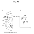
- FIG. 15( a ) is a drawing to show operation when a hearing aid wearer taps the vicinity of a rear sound hole with a tip of nail thereof
- FIG. 15( b ) is a drawing to show an example of a time response in the third embodiment of the invention.
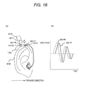
- FIG. 16( a ) is a drawing to show operation when a hearing aid wearer scrubs the hearing aid in a direction from the rear sound hole to the front sound hole with a tip of nail thereof
- FIG. 16( b ) is a drawing to show an example of a time response in the third embodiment of the invention.
- FIG. 17( a ) is a drawing to show operation when a hearing aid wearer scrubs the hearing aid in a direction from the front sound hole to the rear sound hole with a tip of nail thereof
- FIG. 17( b ) is a drawing to show an example of a time response in the third embodiment of the invention.
- the hearing aid detects a sound produced as a hearing aid wearer contacts a hearing aid main body (contact sound) and changes setting (changes an acoustic parameter). For example, if amplitude fluctuation of an input signal exceeds a signal of a second predetermined threshold value or more at least twice in a range of a first predetermined threshold value or less (for example, a state in which no undesired sound exists), setting of the hearing aid is changed. That is, time response of an input signal based on a contact sound generated at the contact time of the hearing aid in a predetermined time period is determined and setting of the hearing aid is changed based on the time response. In this case, the frequency characteristic of the input signal may be limited.
- the acoustic parameters include an environment parameter indicating the environment surrounding the hearing aid, an output parameter indicating the output level of the hearing aid, a noise suppression parameter indicating the suppression level of suppressing noise in the surrounding of the hearing aid, etc.
- setting and changing of the acoustic parameter may be called simply setting and changing.
- the contact sound includes a sound produced as the hearing aid wearer flicks the tip of his or her nail against the hearing aid main body, a tap sound of the tip of his or her nail, a sound produced by stroking a microphone, etc.
- a sound generated in the body of the hearing aid wearer (an occlusion sound of teeth, a gnashing sound, a whistle sound, a tutting sound, etc.,) may be used.
- a played sound from an adjustment device is made a masker sound (masking sound) and a hearing aid adjustment sound is made a maskee sound (masked sound) for making the hearing aid adjustment sound inconspicuous.
- the hearing aid adjustment sound is set to the making level or less of the masker sound (played sound).
- FIG. 1 is a block diagram to shown an example of the schematic configuration of a hearing aid according to a first embodiment of the invention.
- a hearing aid 100 shown in FIG. 1 includes a microphone 101 for generating an input signal from an input sound, an A/D conversion unit 111 for converting the input signal into a digital signal, a signal processing unit 120 for processing the input signal and generating an output signal, a hearing aid signal processing unit 118 for adjusting the frequency characteristic, etc., of a sound signal as the input signal, namely, controlling the frequency characteristic, etc., a D/A conversion unit 119 for converting the digital signal into an analog signal, and a receiver 103 for playing an output sound from an output signal of the provided analog signal.
- Signal processing for the hearing aid includes, for example, nonlinear compression processing for amplifying, etc., a sound signal input at a different amplification factor for each frequency, noise suppression processing for suppressing a noise component input from the microphone 101 , and the like.
- the signal processing for the hearing aid can be performed based on an acoustic parameter as hearing aid setting.
- the signal processing unit 120 has a signal intensity calculation unit 121 for calculating the intensity of an input signal, a threshold value storage unit 123 for storing a predetermined threshold value to be compared with the signal intensity of an input signal, a signal intensity comparison unit 124 for making a comparison between the signal intensity of the input signal and the predetermined threshold value, a signal determination unit 125 for determining a time response of the input signal based on the predetermined threshold value and the comparison result, and a setting control unit 126 for changing setting of the hearing aid based on the determination of the time response.
- the signal determination unit 125 When the signal determination unit 125 detects at least two time points, each at which the average value of the input signal intensity within a predetermined time period is equal to or less than a first threshold value and also at which the input signal intensity within the predetermined time period becomes equal to or more than a second threshold value, the signal determination unit 125 outputs a signal for changing the setting of the hearing aid to the setting control unit 126 .
- the signal determination unit 125 can set the time width for detecting the time point at which the input signal intensity within the predetermined time period becomes equal to or more than the second threshold value. It is considered that a sound produced as the hearing aid wearer flicks the tip of his or her nail against the hearing aid main body (the sound is represented as “nail-tip flick sound”) or a sound produced as the hearing aid wearer taps on the hearing aid main body with the tip of his or her nail (the sound is represented as “nail-tip tap sound”) is used as contact sound of the hearing aid main body by the hearing aid wearer.
- the time width from the start to the end of a nail-tip flick sound or a nail-tip tap sound as one contact sound can be set to 5 msec or more and 20 msec or less, for example.
- the time width is 5 msec or more; it may be less than 5 msec because of development of the frequency analysis processing function of the signal processing unit 120 .
- the time width is prolonged.
- the time width for detecting the nail-tip flick sound or the nail-tip tap sound is shortened as much as possible; for example, it may be 1 msec.
- the time width for detecting a contact sound is shortened, whereby time rising of amplitude caused by a contact sound can be detected precisely.
- smoothing processing of the amplitude value of an input signal in a short time width is performed or averaging processing is performed within a predetermined time period, whereby the detection accuracy of a contact sound can be improved.
- the signal determination unit 125 determines that the signal is a signal for setting the hearing aid, the signal is input to the setting control unit 126 as a setting signal and the setting of the hearing aid is changed by the setting control unit 126 .
- the signal processing unit 120 can decrease the signal intensity for the time width detecting the time point at which the input signal intensity becomes equal to or greater than the second predetermined threshold value within the predetermined time period.
- a method of decreasing the signal intensity a method of converting the input signal intensity into a value less than the first predetermined threshold value, a method of converting the input signal intensity into a value less than the second predetermined threshold value, a method of converting into the sound pressure level equal to that in a time period at which no contact sound is generated, etc., is considered.
- a method of suppressing the signal intensity a method described in JP-A-1-149508 can be applied or an impact sound suppression method described in JP-A-6-276599 can be applied.
- output from the signal processing unit 120 is input to the hearing aid signal processing unit 118 as a signal provided by decreasing the signal intensity of a contact sound generated for changing setting of the hearing aid for the output signal of the A/D conversion unit 111 .
- the hearing aid signal processing unit 118 executes necessary signal processing as the hearing aid, such as directivity synthesis processing, noise suppression processing, howling suppression processing, and nonlinear compression processing.
- the hearing aid signal processing unit 118 adds a signal for informing the hearing aid wearer that the setting change is complete.
- an informing method it is considered that a report sound is generated or that a report is generated by voice.
- the signal processing unit 120 can be configured as in FIG. 2 rather than as in FIG. 1 .
- the signal processing unit 120 shown in FIG. 2 is provided by adding an FFT unit 201 for executing fast Fourier transform of an input signal, thereby converting the signal into data in a frequency domain and a spectrum comparison unit 202 for comparing spectrum of the data in the frequency domain. That is, the signal processing unit 120 in FIG. 1 makes a determination about a time response; the signal processing unit 120 in FIG. 2 makes a determination about a frequency component of an input signal.
- the signal determination unit 125 When the signal determination unit 125 detects at least two time points, at which the average value of the input signal intensity within the predetermined time period is equal to or less than the first predetermined threshold value and also at which the difference between the waveform of the signal in the frequency domain obtained by converting the input signal and the waveform of a predetermined signal becomes equal to or less than a third predetermined threshold value, the signal determination unit 125 changes the setting of the hearing aid. That is, the setting of the hearing aid is changed in response to the analysis result of the signal in the frequency domain.
- the waveform of the predetermined signal is stored in the threshold value storage unit 123 .
- the signal determination unit 125 can set the time width for detecting the time point at which the difference between the waveform of the signal in the frequency domain and the waveform of the predetermined signal becomes equal to or less than the third predetermined threshold value. It is considered that a nail-tip flick sound or a nail-tip tap sound is used as contact sound of the hearing aid main body by the hearing aid wearer. In this case, the time width from the start to the end of the nail-tip flick sound or the nail-tip tap sound as one contact sound can be set to 20 msec or less, for example. For a sound produced by stroking the microphone and a sound produced in the body of the hearing aid wearer, the time width is prolonged.
- the signal determination unit 125 determines that the signal is a signal for setting the hearing aid, the signal is input to the setting control unit 126 as a setting signal and the setting of the hearing aid is changed by the setting control unit 126 .
- the signal processing unit 120 can decrease the signal intensity for the time width detecting the time point at which the difference between the waveform of the frequency signal and the waveform of the predetermined signal becomes equal to or less than the third predetermined threshold value within the predetermined time period.
- a method of decreasing the signal intensity a method of converting the input signal intensity into a value less than the first predetermined threshold value, a method of converting into the sound pressure level equal to that in a time period at which no contact sound is generated, etc., is considered.
- output from the signal processing unit 120 is input to the hearing aid signal processing unit 118 as a signal provided by decreasing the signal intensity of a contact sound generated for changing setting of the hearing aid for the output signal of the A/D conversion unit 111 .
- the hearing aid signal processing unit 118 executes necessary signal processing as the hearing aid, such as directivity synthesis processing, noise suppression processing, howling suppression processing, and nonlinear compression processing.
- the hearing aid signal processing unit 118 adds a signal for informing the hearing aid wearer that the setting change is complete.
- an informing method it is considered that a report sound is generated or that a report is generated by voice.
- a plurality of determination criteria by the signal determination unit 125 may be provided. For example, to distinguish between setting of volume increase and setting of volume decrease, if the signal determination unit 125 detects two time points, at which the average value of the input signal intensity within the predetermined time period is equal to or less than the first threshold value and also at which the input signal intensity within the predetermined time period becomes equal to or more than the second predetermined value, it can be determined that the volume increases and if the signal determination unit 125 detects three times or more, it can be determined that the volume decreases. That is, a plurality of settings of the hearing aid 100 can be distinguished and changed based on the number of detection times. In so doing, it is made possible to distinguish intention of setting change of the hearing aid wearer by the signal determination unit 125 of the hearing aid.
- the type of contact sound generated by different operation of the hearing aid 100 by the hearing aid wearer for example, a nail-tip flick sound, a nail-tip tap sound, a stroke sound with a finger pulp, a sound produced in the body of the hearing aid wearer, etc.
- a nail-tip flick sound for example, a nail-tip flick sound, a nail-tip tap sound, a stroke sound with a finger pulp, a sound produced in the body of the hearing aid wearer, etc.
- the signal amplitude, time fluctuation, frequency characteristic, etc. is used as a different control signal. Accordingly, it is made possible to distinguish intention of setting change of the hearing aid wearer by the signal determination unit 125 of the hearing aid 100 . Accordingly, a plurality of settings can be distinguished and changed and it is made possible to decrease the number of setting change operation times of the hearing aid wearer and circumvent unintended setting change.
- a time response of an input signal is determined and setting of the hearing aid is changed based on the time response, so that setting of the hearing aid (acoustic parameters of volume, operation mode, etc.,) can be easily changed only with the hearing aid without performing button operation of a miniaturized hearing aid and without using another device.
- setting of the hearing aid acoustic parameters of volume, operation mode, etc.
- the behind-the-ear hearing aid refers to a hearing aid with the overall length of a hearing aid main body (the main body refers to a main body portion except a hunger portion or a tube portion) being about 3 cm or more, and the small-size behind-the-ear hearing aid refers to a hearing aid with the overall length of a hearing aid main body being less than about 3 cm.
- FIG. 5 is a graph when a nail-tip flick sound (an example of a contact sound) is applied to a behind-the-ear hearing aid (experiment model A) as operation of the hearing aid wearer.
- FIG. 5( a ) shows time response of input signal amplitude, the horizontal axis indicates the time (in second units), and the vertical axis indicates sound pressure level (here, the maximum input sound pressure level is described as 0 dB).
- FIG. 5( b ) is an enlarged drawing in the time direction of an impulse waveform of time response, the horizontal axis indicates the time (in millisecond units), and the vertical axis indicates sound pressure level.
- FIG. 5( c ) shows the frequency characteristic of time response, the horizontal axis indicates frequency (in Hz units), and the vertical axis indicates sound pressure level.
- th 1 (line of ⁇ 15 dB)) indicates an example of the first predetermined threshold value and th 2 (line of ⁇ 9 dB) indicates an example of the second predetermined threshold value.
- ti indicates an example of the predetermined time width and d indicates an example of the time width.
- FIG. 6 is a graph when a nail-tip flick sound (an example of a contact sound) is applied to a small-size behind-the-ear hearing aid (experiment model B) as operation of the hearing aid wearer.
- FIG. 6( a ) shows time response of input signal amplitude, the horizontal axis indicates the time (in second units), and the vertical axis indicates sound pressure level.
- FIG. 6( b ) is an enlarged drawing in the time direction of an impulse waveform of time response, the horizontal axis indicates the time (in millisecond units), and the vertical axis indicates sound pressure level.
- FIG. 6( c ) shows the frequency characteristic of time response, the horizontal axis indicates frequency (in Hz units), and the vertical axis indicates sound pressure level.
- the hearing aid and the small-size behind-the-ear hearing aid when the time response of the input signal amplitude in FIG. 6( a ) is compared with an example of another contact sound, it can be understood that the sound pressure level of the nail-tip flick sound is large. Therefore, when the hearing aid wearer flicks the tip of his or her nail against the hearing aids, the sound pressure level reliably exceeds the second predetermined threshold value and setting of the hearing aid can be reliably changed.
- FIG. 7 is a graph when a nail-tip tap sound (an example of a contact sound) is applied to the behind-the-ear hearing aid (experiment model A) as operation of the hearing aid wearer.
- FIG. 7( a ) shows time response of input signal amplitude, the horizontal axis indicates the time (in second units), and the vertical axis indicates sound pressure level.
- FIG. 7( b ) is an enlarged drawing in the time direction of an impulse waveform of time response, the horizontal axis indicates the time (in millisecond units), and the vertical axis indicates sound pressure level.
- FIG. 7( c ) shows the frequency characteristic of time response, the horizontal axis indicates frequency (in Hz units), and the vertical axis indicates sound pressure level.
- FIG. 8 is a graph when a nail-tip tap sound (an example of a contact sound) is applied to the small-size behind-the-ear hearing aid (experiment model B) as operation of the hearing aid wearer.
- FIG. 8( a ) shows time response of input signal amplitude, the horizontal axis indicates the time (in second units), and the vertical axis indicates sound pressure level.
- FIG. 8( b ) is an enlarged drawing in the time direction of an impulse waveform of time response, the horizontal axis indicates the time (in millisecond units), and the vertical axis indicates sound pressure level.
- FIG. 8( c ) shows the frequency characteristic of time response, the horizontal axis indicates frequency (in Hz units), and the vertical axis indicates sound pressure level.
- FIG. 9 is a graph when a stroke sound with a finger pulp (an example of a contact sound) is applied to the hearing aid as operation of the hearing aid wearer.
- FIG. 9( a ) shows time response of input signal amplitude, the horizontal axis indicates the time (in second units), and the vertical axis indicates sound pressure level.
- FIG. 9( b ) is an enlarged drawing in the time direction of an impulse waveform of time response, the horizontal axis indicates the time (in millisecond units), and the vertical axis indicates sound pressure level.
- FIG. 9( c ) shows the frequency characteristic of time response, the horizontal axis indicates frequency (in Hz units), and the vertical axis indicates sound pressure level.
- the recording microphone 101 and the sound source are very close to each other and thus the effect caused by the difference between the hearing aid shapes (behind-the-ear hearing aid and in-the-ear hearing aid) is small as compared with nail-tip flick sound, nail-tip tap sound, and sound produced in the body of the hearing aid wearer.
- FIG. 10 is a graph when a chewing sound (an example of a contact sound) is applied to the behind-the-ear hearing aid as operation of the hearing aid wearer (the measurement place is an upper part of a pinna).
- FIG. 10( a ) shows time response of input signal amplitude, the horizontal axis indicates the time (in second units), and the vertical axis indicates sound pressure level.
- FIG. 10( b ) is an enlarged drawing in the time direction of an impulse waveform of time response, the horizontal axis indicates the time (in millisecond units), and the vertical axis indicates sound pressure level.
- FIG. 10( c ) shows the frequency characteristic of time response, the horizontal axis indicates frequency (in Hz units), and the vertical axis indicates sound pressure level.
- FIG. 11 is a graph when a chewing sound (an example of a contact sound) is applied to an in-the-ear hearing aid as operation of the hearing aid wearer (the measurement place is the inside of an external auditory meatus).
- FIG. 11( a ) shows time response of input signal amplitude, the horizontal axis indicates the time (in second units), and the vertical axis indicates sound pressure level.
- FIG. 11 ( b ) is an enlarged drawing in the time direction of an impulse waveform of time response, the horizontal axis indicates the time (in millisecond units), and the vertical axis indicates sound pressure level.
- FIG. 11( c ) shows the frequency characteristic of time response, the horizontal axis indicates frequency (in Hz units), and the vertical axis indicates sound pressure level.
- the hearing aid for example, if a sound produced as the hearing aid wearer flicks the tip of his or her nail against the hearing aid or a tap sound is used as an input signal, the case where the intensity of an input signal becomes equal to or more than the threshold value can be reliably detected and setting of the hearing aid (acoustic parameters of volume, operation mode, etc.,) can also be reliably changed in a noisy ordinary environment.
- the nail-tip flick sound is most easily detected and the nail-tip tap sound is second most easily detected. Therefore, adopting the nail-tip flick sound as a contact sound is most preferred and adopting the nail-tip tap sound as a contact sound is second most preferred.
- FIG. 3 is a block diagram to shown an example of the schematic configuration of a hearing aid system according to a second embodiment of the invention.
- the hearing aid system of the embodiment is made up of a hearing aid setting device 400 and a hearing aid 100 .
- the hearing aid setting device 400 includes a setting selection unit 401 to which predetermined setting of the hearing aid is input, a masker sound storage unit 403 for storing a masker sound (masking sound), a maskee sound storage unit 404 for storing a maskee sound (masked sound), a setting sound synthesis unit 405 for synthesizing a setting sound from the masker sound and the maskee sound based on the hearing aid setting, a D/A conversion unit 407 for converting the setting sound into an analog signal, and a speaker 408 for outputting the setting sound.
- Components identical with those of the hearing aid according to the first embodiment are denoted by the same reference numerals and will not be discussed again or will be simplified.
- Masking refers to a phenomenon in which one sound is hard to hear in the presence of another sound as a telephone call is made in a place where noise is strong, for example.
- the masking sound (maker sound) is kept at a given sense level, the level of the masked sound (maskee sound) is gradually raised from a state in which it is not heard, the level at which the sound starts to be heard, namely, the minimum audible value of the maskee sound when the masker sound exists is found, and deviation from the minimum audible value when no masker sound exists is represented as dB and is adopted as the masking level.
- the masker sound may be a ringtone.
- the maskee sound is an adjustment sound output, for example, when setting of the hearing aid is changed and is a conventional setting sound like “pipipi,” for example.
- the maskee sound is set to the masking level or less of the masker sound, whereby the hearing aid wearer does not feel unpleasant at the setting time of the hearing aid.
- the masker sound may be able to be set appropriately in response to the liking of the hearing aid wearer.
- the frequency component contained in the maskee sound is not contained in the masker sound.
- the reason is as follows: Considering that hearing aid setting operation is performed according to a command of the hearing aid wearer, since the distance between the hearing aid setting device and the hearing aid is not necessarily constant, if played sound of the hearing aid setting device is constant, it is considered that the sound pressure level of the input sound of the hearing aid fluctuates. In this case, if the same frequency component is contained, it becomes difficult to extract the maskee sound from the masker sound.
- a specific example of the setting sound is a sound containing a ringtone and a conventional setting sound if the setting device is a mobile telephone, for example. If the setting device is a mobile telephone, a mode is also considered wherein a setting sound provided by combining the maskee sound and the masker sound is previously downloaded from a server to the mobile telephone and is played in the mobile telephone and setting of the hearing aid is changed.
- the setting sound synthesis unit 405 When hearing aid setting is input from the setting selection unit 401 , the setting sound synthesis unit 405 combines the maskee sound stored in the maskee sound storage unit 404 and the masker sound stored in the masker sound storage unit 403 in response to the hearing aid setting supplied from the setting selection unit 401 to generate an output signal output from the speaker 408 as setting sound.
- the masker sound and the maskee sound are previously generated by a sound source generator that can adjust and output a frequency and sound pressure level to change setting of the hearing aid 100 .
- the sound source generator When the sound source generator generates the masker sound, it is desirable that a sound source in which the masker sound does not contain the frequency component contained in the maskee sound, namely, a sound source containing any other frequency component than the frequency component contained in the maskee sound should be selected.
- a sound source in which the masker sound does not contain the frequency component contained in the maskee sound namely, a sound source containing any other frequency component than the frequency component contained in the maskee sound should be selected.
- a non-dissonant sound for example, music, etc.
- the sound source generator When the sound source generator generates the maskee sound, it is considered that the sound has a single frequency component or has a plurality of frequency components. If the maskee sound is a single frequency component, the computation amount of signal processing can be lightened. On the other hand, if the maskee sound is a plurality of frequency components, there is a possibility that the setting sound can be shortened.
- the maskee sound thus generated is stored in the maskee sound storage unit 404 .
- the hearing aid 100 includes a microphone 101 for collecting a setting sound 410 , an A/D conversion unit 111 for converting the setting sound 410 into a digital signal, a setting change signal processing unit 420 for extracting hearing aid setting from the setting sound, a hearing aid signal processing unit 118 for adjusting the frequency characteristic, etc., of a sound signal, a D/A conversion unit 119 for converting a digital signal into an analog signal, and a receiver 103 for playing an output sound from an output signal of the provided analog signal.
- the microphone 101 detects the setting sound 410 output from the speaker 408 and the A/D conversion unit converts the setting sound 410 into a digital signal (setting signal).
- the setting change signal processing unit 420 extracts a maskee sound from the setting signal and further extracts hearing aid setting from the maskee sound and changes setting of the hearing aid.
- the maskee sound can be set to the masking level or less of a masker sound. This means that the signal intensity of the signal indicating the masker sound can made smaller than the signal intensity of the signal indicating the masker sound.
- the maskee sound can be made a pure sound (sound of single frequency).
- the maskee sound is made a pure sound, whereby the information amount of the signal lessens and the processing load is lightened.
- FIG. 4 is a schematic drawing to show the internal configuration of a setting change signal processing unit 420 .
- the setting change signal processing unit 420 has an FFT unit 201 for executing fast Fourier transform of an input signal, thereby converting the signal into data in a frequency domain, a threshold value storage unit 501 for storing a predetermined threshold value to be compared with the signal intensity of an input signal, a maskee sound extraction unit 502 for extracting a maskee sound from a setting sound as the input signal, a signal determination unit 503 for extracting hearing aid setting from the extracted maskee sound and a predetermined threshold value, and a setting control unit 126 for changing setting based on the extracted hearing aid setting.
- FFT unit 201 for executing fast Fourier transform of an input signal, thereby converting the signal into data in a frequency domain
- a threshold value storage unit 501 for storing a predetermined threshold value to be compared with the signal intensity of an input signal
- a maskee sound extraction unit 502 for extracting
- the hearing aid 100 stores the maskee sound or the features of the maskee sound (for example, frequency component, frequency signal level, and the like) and the maskee sound extraction unit 502 extracts the maskee sound from the setting sound based on the storage contents.
- the maskee sound extraction unit 502 pays attention to the features of the maskee sound (for example, frequency component) from a signal for each frequency component output by the FFT unit 201 and generates information as to whether or not the maskee sound is contained. Limitation that the frequency component contained in the maskee sound is not contained is added to the masker sound, whereby the maskee sound can be extracted.
- the signal determination unit 503 calculates setting change for the hearing aid based on the extracted maskee sound. If the maskee sound is a pure sound, a predetermined threshold value is set for the frequency band corresponding to the maskee sound on a frequency axis and if the predetermined threshold value is exceeded at least twice or more on a time axis, setting change of the hearing aid is determined. Exceeding the threshold value at least twice or more is set for the purpose of preventing malfunction.
- the maskee sound is a combination of pure sounds.
- the signal determination unit 503 sets a predetermined threshold value for the pure sounds and if all or any of the pure sounds exceeds the predetermined threshold value, setting change of the hearing aid is determined.
- processing of detecting that the predetermined threshold value is exceeded at least twice or more on the time axis for the purpose of preventing malfunction can be omitted.
- hearing aid setting is extracted from the extracted maskee sound and setting is changed based on the extracted hearing aid setting, so that a dissonant adjustment sound is not heard at the setting time and a displeasure sense is not given to the hearing aid wearer.
- Purposes of a hearing aid according to a third embodiment of the invention is to decrease the number of setting change times of a hearing aid wearer and prevent setting change not intended by the hearing aid wearer.
- the case where, for example, when an increase or decrease in the volume of a hearing aid is set, for example, different setting cannot be made in the increase direction and the decrease direction and volume setting switches as it goes round is considered.
- the case where as round setting, the volume once increases and reaches the upper limit and then switches to the lower limit although the hearing aid wearer wants to decrease the volume is considered.
- the hearing aid wearer needs to change setting more than once and a volume increase is temporarily set as he or she does not intend it; the hearing aid wearer feels inconvenient.
- a method of distinguishing the operation difference of the hearing aid wearer by the hearing aid, thereby distinguishing between volume increase and volume decrease and reflecting setting as intended by one operation will be discussed.
- FIG. 13 is a block diagram to show an example of the schematic configuration of a hearing aid according to the third embodiment of the invention.
- the hearing aid 100 shown in FIG. 1 includes one microphone 101 ; while, the hearing aid in FIG. 13 includes two microphones of a front microphone 101 F and a rear microphone 101 R.
- the configuration in which two microphones are installed in a hearing aid is generally used as the configuration for realizing a directivity synthesis function of suppressing a back sound and making a forward sound easy to hear. Parts identical with those in FIG. 1 where one microphone is installed will not be discussed again with FIG. 13 and a signal processing unit 120 different from that in FIG. 1 will be discussed.
- a front microphone 101 F is placed on the front side in the forward direction shown in FIGS. 14 to 17 when a hearing aid 100 is worn in an ear of a hearing aid wearer, and a rear microphone 101 R is placed on the back side in the forward direction shown in FIGS. 14 to 17 when the hearing aid 100 is worn in the ear of the hearing aid wearer.
- the signal processing unit 120 inputs input signals from the front microphone 101 F and the rear microphone 101 R.
- a signal intensity calculation unit 121 a threshold value storage unit 123 , a signal intensity comparison unit 124 , and a signal determination unit 125 are components for performing the same processing as those in FIG. 1 .
- a front and rear microphone signal comparison unit 610 makes a comparison between the determination result for the input signal in the front microphone 101 F and the determination result for the input signal in the rear microphone 101 R. Processing of the front and rear microphone signal comparison unit 610 will be discussed with FIGS. 14 to 17 . Setting distinguished by the front and rear microphone signal comparison unit 610 is reflected on a setting control unit 126 .
- the signal processing unit 120 determines time responses of the input signal of the front microphone 101 F and the input signal of the rear microphone 101 R based on a contact sound generated when the hearing aid 100 is contacted in a predetermined time period.
- the signal processing unit 120 distinguishes a plurality of settings of the hearing aid 100 and changes the setting based on the determined time responses.
- the plurality of settings may be change setting in the increase direction of the volume and change setting in the decrease direction of the volume, for example.
- FIGS. 14 to 17 are made up of FIGS. 14( a ) to 17 ( a ) to show operation of the behind-the-ear hearing aid 100 installing two microphones by the hearing aid wearer and FIGS. 14( b ) to 17 ( b ) to show examples of time responses of input signals from the front microphone 101 F and the rear microphone 101 R of the hearing aid 100 .
- FIGS. 14 and 15 represent the case where the hearing aid wearer taps the vicinity of the microphone 101 of the hearing aid 100 with the tip of nail of a finger or flicks the tip of nail of a finger against the vicinity of the microphone 101 of the hearing aid 100 as operation for changing setting.
- FIGS. 14 and 15 represent the case where the hearing aid wearer taps the vicinity of the microphone 101 of the hearing aid 100 with the tip of nail of a finger or flicks the tip of nail of a finger against the vicinity of the microphone 101 of the hearing aid 100 as operation for changing setting.
- 16 and 17 represent the case where the hearing aid wearer scrubs or strokes the vicinity of the microphone 101 of the hearing aid with the tip of nail of a finger or a finger pulp as operation for changing setting.
- FIGS. 14 to 17 the behind-the-ear hearing aid is described and the embodiment can also be applied to canal type, concha type, CIC type, etc., of in-the-ear hearing aids.
- FIG. 14 assumes the case where the hearing aid wearer taps the vicinity of the front microphone 101 F of the hearing aid 100 with a tip of nail of a finger 911 or flicks the tip of nail of the finger 911 against the vicinity of the front microphone 101 F of the hearing aid 100 to change setting.
- FIG. 14( a ) is a drawing to show the operation and
- FIG. 14( b ) is a drawing to show time response in the case.
- FIG. 14( a ) shows that the behind-the-ear hearing aid 100 is worn in a pinna 900 of the hearing aid wearer and setting change operation is performed with a finger 910 .
- Two microphones are installed in the hearing aid 100 and the front microphone 101 F and the rear microphone 101 R exist. To input a sound into each microphone, the front microphone 101 F has a front sound hole 601 F and the rear microphone 101 R has a rear sound hole 601 R.
- FIG. 14( b ) shows a time response 621 F of an input signal of the front microphone 101 F and a time response 621 R of an input signal of the rear microphone 101 R when the hearing aid wearer taps the vicinity of the front microphone 101 F of the hearing aid 100 with the tip of nail of the finger 911 or flicks the tip of nail of the finger 911 against the vicinity of the front microphone 101 F of the hearing aid 100 .
- the time response 621 F has a larger amplitude than the time response 621 R. Accordingly, the hearing aid 100 distinguishes the hearing aid wearer contacting the vicinity of the front microphone 101 F.
- FIG. 15 assumes the case where the hearing aid wearer taps the vicinity of the rear microphone 101 R of the hearing aid 100 with the tip of nail of the finger 911 or flicks the tip of nail of the finger 911 against the vicinity of the rear microphone 101 R of the hearing aid 100 to change setting.
- FIG. 15( a ) is a drawing to show the operation and
- FIG. 15( b ) is a drawing to show time response in the case.
- FIG. 15( a ) differs from FIG. 14( a ) in that the hearing aid wearer taps the vicinity of the rear microphone 101 R of the hearing aid 100 with the tip of nail or flicks the tip of nail against the vicinity of the rear microphone 101 R to change setting of the hearing aid 100 .
- FIG. 15( b ) shows a time response 622 F of an input signal of the front microphone 101 F and a time response 622 R of an input signal of the rear microphone 101 R when the hearing aid wearer taps the vicinity of the rear microphone 101 R of the hearing aid 100 with the tip of nail of the finger 911 or flicks the tip of nail of the finger 911 against the vicinity of the rear microphone 101 R of the hearing aid 100 .
- the time response 622 R has a larger amplitude than the time response 622 F. Accordingly, the hearing aid 100 distinguishes the hearing aid wearer contacting the vicinity of the rear microphone 101 R.
- the place where the hearing aid wearer taps the hearing aid 100 with the tip of nail or flicks the tip of nail against the hearing aid 100 is changed, whereby the front and rear microphone signal comparison unit 610 of the hearing aid 100 can distinguish operation of the hearing aid wearer.
- the front and rear microphone signal comparison unit 610 makes a comparison between the amplitude values of the input signals shown in the time response 621 F and the time response 621 R, and the setting control unit 126 distinguishes a plurality of settings of the hearing aid and changes the setting based on the amplitudes. Accordingly, the hearing aid 100 can distinguish the intention of the hearing aid wearer, the hearing aid wearer does not feel unpleasant, and it is made possible to change setting as intended.
- FIG. 16 assumes the case where the hearing aid wearer scrubs or strokes the hearing aid 100 in a direction from the rear microphone 101 R to the front microphone 101 F with the tip of nail of the finger 911 to change setting.
- FIG. 16( a ) is a drawing to show the operation and
- FIG. 16( b ) is a drawing to show time response in the case.
- FIG. 16( a ) differs from FIG. 14( a ) in that the hearing aid wearer scrubs or strokes the hearing aid 100 in the direction from the rear microphone 101 F to the front microphone 101 F with the tip of nail of the finger 911 to change setting of the hearing aid 100 , for example. That is, the operation is operation of contacting the hearing aid 100 with the tip of nail of the finger 911 and moving the finger in the arrow direction shown in FIG. 16( a ).
- FIG. 16( b ) shows a time response 631 F of an input signal of the front microphone 101 F and a time response 631 R of an input signal of the rear microphone 101 R when the hearing aid wearer scrubs or strokes the hearing aid 100 in the direction from the rear microphone 101 R to the front microphone 101 F of the hearing aid 100 with the tip of nail of the finger 911 .
- the peak portion of the amplitude of the time response 631 F appears earlier on a time axis than that of the time response 631 F. Accordingly, the hearing aid 100 can distinguish operation of scrubbing or stroking the hearing aid 100 from the rear to the front by the hearing aid wearer.
- FIG. 17 assumes the case where the hearing aid wearer scrubs or strokes the hearing aid 100 in a direction from the front microphone 101 F to the rear microphone 101 R with the tip of nail of the finger 911 to change setting.
- FIG. 17( a ) is a drawing to show the operation and
- FIG. 17( b ) is a drawing to show time response in the case.
- FIG. 17( a ) differs from FIG. 16( a ) in that the hearing aid wearer scrubs or strokes the hearing aid 100 in the direction from the front microphone 101 F to the rear microphone 101 F with the tip of nail of the finger 911 to change setting of the hearing aid 100 , for example. That is, the operation is operation of contacting the hearing aid 100 with the tip of nail of the finger 911 and moving the finger in the arrow direction shown in FIG. 17( a ).
- FIG. 17( b ) shows a time response 632 F of an input signal of the front microphone 101 F and a time response 632 R of an input signal of the rear microphone 101 R when the hearing aid wearer scrubs or strokes the hearing aid 100 in the direction from the front microphone 101 F to the rear microphone 101 R of the hearing aid 100 with the tip of nail of the finger 911 .
- the peak portion of the amplitude of the time response 632 F appears earlier on a time axis than that of the time response 632 F. Accordingly, the hearing aid 100 can distinguish operation of scrubbing or stroking the hearing aid 100 from the front to the rear by the hearing aid wearer.
- the front and rear microphone signal comparison unit 610 of the hearing aid 100 can distinguish operation of scrubbing or stroking the hearing aid 100 in the direction from the rear microphone 101 R to the front microphone 101 F or in the direction from the front microphone 101 F to the rear microphone 101 R with the tip of nail of the hearing aid wearer.
- the front and rear microphone signal comparison unit 610 determines the time difference between the amplitude peak time points of input signals indicated in the time response 621 F and the time response 621 R, and the setting control unit 126 distinguishes a plurality of settings of the hearing aid and changes the setting based on the time difference between the amplitude peak time points. Accordingly, the hearing aid 100 can distinguish the intention of the hearing aid wearer, the hearing aid wearer does not feel unpleasant, and it is made possible to change setting as intended.
- a variable volume change switch shaped like a disk may be used as volume setting means, and operation of the switch and operation of scrubbing or stroking the hearing aid of the embodiment resemble each other.
- operation of scrubbing or stroking is performed as operation of increasing or decreasing the volume, whereby erroneous operation of setting the volume by the hearing aid wearer can be easily decreased.
- the invention is useful as a hearing aid, a hearing system, etc., for preventing the user from feeling his or her displeasure caused by changing setting of the hearing aid and further enabling the user to easily change the setting.
Applications Claiming Priority (3)
| Application Number | Priority Date | Filing Date | Title |
|---|---|---|---|
| JP2008-212050 | 2008-08-20 | ||
| JP2008212050 | 2008-08-20 | ||
| PCT/JP2009/003931 WO2010021125A1 (ja) | 2008-08-20 | 2009-08-18 | 補聴器および補聴器システム |
Related Parent Applications (1)
| Application Number | Title | Priority Date | Filing Date |
|---|---|---|---|
| PCT/JP2009/003931 A-371-Of-International WO2010021125A1 (ja) | 2008-08-20 | 2009-08-18 | 補聴器および補聴器システム |
Related Child Applications (1)
| Application Number | Title | Priority Date | Filing Date |
|---|---|---|---|
| US13/232,030 Division US8488825B2 (en) | 2008-08-20 | 2011-09-14 | Hearing aid and hearing aid system |
Publications (2)
| Publication Number | Publication Date |
|---|---|
| US20110142273A1 US20110142273A1 (en) | 2011-06-16 |
| US8041063B2 true US8041063B2 (en) | 2011-10-18 |
Family
ID=41707016
Family Applications (2)
| Application Number | Title | Priority Date | Filing Date |
|---|---|---|---|
| US13/059,875 Expired - Fee Related US8041063B2 (en) | 2008-08-20 | 2009-08-18 | Hearing aid and hearing aid system |
| US13/232,030 Expired - Fee Related US8488825B2 (en) | 2008-08-20 | 2011-09-14 | Hearing aid and hearing aid system |
Family Applications After (1)
| Application Number | Title | Priority Date | Filing Date |
|---|---|---|---|
| US13/232,030 Expired - Fee Related US8488825B2 (en) | 2008-08-20 | 2011-09-14 | Hearing aid and hearing aid system |
Country Status (3)
| Country | Link |
|---|---|
| US (2) | US8041063B2 (ja) |
| JP (1) | JP4727763B2 (ja) |
| WO (1) | WO2010021125A1 (ja) |
Cited By (2)
| Publication number | Priority date | Publication date | Assignee | Title |
|---|---|---|---|---|
| US20120004913A1 (en) * | 2010-07-01 | 2012-01-05 | Samsung Electronics Co., Ltd. | Method and apparatus for controlling operation of portable terminal using microphone |
| US11665491B2 (en) | 2020-05-22 | 2023-05-30 | Team Ip Holdings, Llc | Face mask with audio device holder |
Families Citing this family (9)
| Publication number | Priority date | Publication date | Assignee | Title |
|---|---|---|---|---|
| DE102009021855A1 (de) * | 2009-05-19 | 2010-11-25 | Siemens Medical Instruments Pte. Ltd. | Verfahren zur Akklimatisierung einer programmierbaren Hörvorrichtung und zugehörige Hörvorrichtung |
| US8792661B2 (en) * | 2010-01-20 | 2014-07-29 | Audiotoniq, Inc. | Hearing aids, computing devices, and methods for hearing aid profile update |
| JP5716595B2 (ja) * | 2011-01-28 | 2015-05-13 | 富士通株式会社 | 音声補正装置、音声補正方法及び音声補正プログラム |
| JP2012194901A (ja) * | 2011-03-17 | 2012-10-11 | Sharp Corp | 電子機器、電子機器の制御方法、制御プログラムおよび記録媒体 |
| JP2012244582A (ja) * | 2011-05-24 | 2012-12-10 | Rion Co Ltd | 補聴器 |
| US8964509B2 (en) * | 2011-12-21 | 2015-02-24 | Utc Fire & Security Corporation | Remote communication and control of acoustic detectors |
| KR101976091B1 (ko) * | 2013-01-24 | 2019-05-09 | 삼성전자주식회사 | 청각 기기의 동작 모드를 결정하는 방법 및 청각 기기 |
| TWI544478B (zh) * | 2014-04-10 | 2016-08-01 | 拓集科技股份有限公司 | 基於聲音觸發之作業啟始方法及系統,及相關電腦程式產品 |
| US11032656B2 (en) | 2017-06-06 | 2021-06-08 | Gn Hearing A/S | Audition of hearing device settings, associated system and hearing device |
Citations (13)
| Publication number | Priority date | Publication date | Assignee | Title |
|---|---|---|---|---|
| DE2846492A1 (de) | 1977-10-27 | 1979-05-10 | Latszereszeti Eszkoezoek Gyara | Schaltungsanordnung zur kontinuierlichen lautstaerke- und/oder klangfarbenregelung |
| JPH01149508A (ja) | 1987-12-04 | 1989-06-12 | Sony Corp | 音響信号処理回路 |
| JPH05130695A (ja) | 1991-11-01 | 1993-05-25 | Matsushita Electric Ind Co Ltd | 補聴器 |
| JPH06276599A (ja) | 1991-07-26 | 1994-09-30 | Gijutsu Kenkyu Kumiai Iryo Fukushi Kiki Kenkyusho | 衝撃音抑圧装置 |
| JPH0918998A (ja) | 1995-06-29 | 1997-01-17 | Rion Co Ltd | 耳かけ形補聴器 |
| WO2002005590A1 (en) | 2000-06-30 | 2002-01-17 | Cochlear Limited | Cochlear implant |
| CA2422449A1 (en) | 2000-09-18 | 2003-03-06 | Phonak Ag | Method for controlling a transmission system, use of this method, transmission system, receiving unit and hearing aid |
| JP3482465B2 (ja) | 2001-01-25 | 2003-12-22 | 独立行政法人産業技術総合研究所 | モバイルフィッティングシステム |
| US6910013B2 (en) * | 2001-01-05 | 2005-06-21 | Phonak Ag | Method for identifying a momentary acoustic scene, application of said method, and a hearing device |
| JP2005203981A (ja) | 2004-01-14 | 2005-07-28 | Fujitsu Ltd | 音響信号処理装置および音響信号処理方法 |
| JP2006229866A (ja) | 2005-02-21 | 2006-08-31 | Matsushita Electric Ind Co Ltd | 補聴器を遠隔制御する補聴器システム |
| WO2007052185A2 (en) | 2005-11-01 | 2007-05-10 | Koninklijke Philips Electronics N.V. | Hearing aid comprising sound tracking means |
| US7650005B2 (en) * | 2005-05-02 | 2010-01-19 | Siemens Audiologische Technik Gmbh | Automatic gain adjustment for a hearing aid device |
Family Cites Families (2)
| Publication number | Priority date | Publication date | Assignee | Title |
|---|---|---|---|---|
| GB8424471D0 (en) * | 1984-09-27 | 1984-10-31 | Bordewijk L G | Remote control system for hearing-aid |
| US6236731B1 (en) * | 1997-04-16 | 2001-05-22 | Dspfactory Ltd. | Filterbank structure and method for filtering and separating an information signal into different bands, particularly for audio signal in hearing aids |
-
2009
- 2009-08-18 JP JP2010525593A patent/JP4727763B2/ja not_active Expired - Fee Related
- 2009-08-18 US US13/059,875 patent/US8041063B2/en not_active Expired - Fee Related
- 2009-08-18 WO PCT/JP2009/003931 patent/WO2010021125A1/ja active Application Filing
-
2011
- 2011-09-14 US US13/232,030 patent/US8488825B2/en not_active Expired - Fee Related
Patent Citations (16)
| Publication number | Priority date | Publication date | Assignee | Title |
|---|---|---|---|---|
| JPS54109303A (en) | 1977-10-27 | 1979-08-27 | Latszereszeti Eszkoezoek Gyara | Hearing aid volume and*or tone pitch continuous control circuit device |
| DE2846492A1 (de) | 1977-10-27 | 1979-05-10 | Latszereszeti Eszkoezoek Gyara | Schaltungsanordnung zur kontinuierlichen lautstaerke- und/oder klangfarbenregelung |
| JPH01149508A (ja) | 1987-12-04 | 1989-06-12 | Sony Corp | 音響信号処理回路 |
| JPH06276599A (ja) | 1991-07-26 | 1994-09-30 | Gijutsu Kenkyu Kumiai Iryo Fukushi Kiki Kenkyusho | 衝撃音抑圧装置 |
| JPH05130695A (ja) | 1991-11-01 | 1993-05-25 | Matsushita Electric Ind Co Ltd | 補聴器 |
| JPH0918998A (ja) | 1995-06-29 | 1997-01-17 | Rion Co Ltd | 耳かけ形補聴器 |
| WO2002005590A1 (en) | 2000-06-30 | 2002-01-17 | Cochlear Limited | Cochlear implant |
| JP2004501738A (ja) | 2000-06-30 | 2004-01-22 | コックリアー,リミテッド | 蝸牛インプラント |
| CA2422449A1 (en) | 2000-09-18 | 2003-03-06 | Phonak Ag | Method for controlling a transmission system, use of this method, transmission system, receiving unit and hearing aid |
| JP2004522333A (ja) | 2000-09-18 | 2004-07-22 | フォーナック アーゲー | 伝送システムの制御方法、同方法の適用、伝送システム、受信装置及び補聴器 |
| US6910013B2 (en) * | 2001-01-05 | 2005-06-21 | Phonak Ag | Method for identifying a momentary acoustic scene, application of said method, and a hearing device |
| JP3482465B2 (ja) | 2001-01-25 | 2003-12-22 | 独立行政法人産業技術総合研究所 | モバイルフィッティングシステム |
| JP2005203981A (ja) | 2004-01-14 | 2005-07-28 | Fujitsu Ltd | 音響信号処理装置および音響信号処理方法 |
| JP2006229866A (ja) | 2005-02-21 | 2006-08-31 | Matsushita Electric Ind Co Ltd | 補聴器を遠隔制御する補聴器システム |
| US7650005B2 (en) * | 2005-05-02 | 2010-01-19 | Siemens Audiologische Technik Gmbh | Automatic gain adjustment for a hearing aid device |
| WO2007052185A2 (en) | 2005-11-01 | 2007-05-10 | Koninklijke Philips Electronics N.V. | Hearing aid comprising sound tracking means |
Non-Patent Citations (1)
| Title |
|---|
| International Search Report of PCT Application No. PCT/JP2009/003931, dated Nov. 2, 2009. |
Cited By (2)
| Publication number | Priority date | Publication date | Assignee | Title |
|---|---|---|---|---|
| US20120004913A1 (en) * | 2010-07-01 | 2012-01-05 | Samsung Electronics Co., Ltd. | Method and apparatus for controlling operation of portable terminal using microphone |
| US11665491B2 (en) | 2020-05-22 | 2023-05-30 | Team Ip Holdings, Llc | Face mask with audio device holder |
Also Published As
| Publication number | Publication date |
|---|---|
| US20120002829A1 (en) | 2012-01-05 |
| JPWO2010021125A1 (ja) | 2012-01-26 |
| US8488825B2 (en) | 2013-07-16 |
| WO2010021125A1 (ja) | 2010-02-25 |
| JP4727763B2 (ja) | 2011-07-20 |
| US20110142273A1 (en) | 2011-06-16 |
Similar Documents
| Publication | Publication Date | Title |
|---|---|---|
| US8041063B2 (en) | Hearing aid and hearing aid system | |
| US8442246B2 (en) | Hearing aid device and hearing aid method | |
| US9319814B2 (en) | Method for fitting a hearing aid device with active occlusion control to a user | |
| JP5256119B2 (ja) | 補聴器並びに補聴器に用いられる補聴処理方法及び集積回路 | |
| EP3567869B1 (en) | Advanced communication earpiece device and method | |
| EP2536170B1 (en) | Hearing aid, signal processing method and program | |
| US9232322B2 (en) | Hearing aid devices with reduced background and feedback noises | |
| US8649539B2 (en) | Method for processing the signals from two or more microphones in a listening device and listening device with plural microphones | |
| US8358797B2 (en) | Switch for a hearing aid | |
| CN103517192A (zh) | 包括反馈报警的助听器 | |
| WO2016069615A1 (en) | Self-voice occlusion mitigation in headsets | |
| CN106686496B (zh) | 一种可穿戴设备的播放模式控制方法及可穿戴设备 | |
| US20130188811A1 (en) | Method of controlling sounds generated in a hearing aid and a hearing aid | |
| US8107660B2 (en) | Hearing aid | |
| EP2107826A1 (en) | A directional hearing aid system | |
| US10873816B2 (en) | Providing feedback of an own voice loudness of a user of a hearing device | |
| WO2011067928A1 (ja) | 補聴器 | |
| JP2008177745A (ja) | 放収音システム |
Legal Events
| Date | Code | Title | Description |
|---|---|---|---|
| AS | Assignment |
Owner name: PANASONIC CORPORATION, JAPAN Free format text: ASSIGNMENT OF ASSIGNORS INTEREST;ASSIGNORS:IWANO, KENJI;MURASE, ATSUNOBU;REEL/FRAME:026178/0323 Effective date: 20101210 |
|
| FEPP | Fee payment procedure |
Free format text: PAYOR NUMBER ASSIGNED (ORIGINAL EVENT CODE: ASPN); ENTITY STATUS OF PATENT OWNER: LARGE ENTITY |
|
| REMI | Maintenance fee reminder mailed | ||
| LAPS | Lapse for failure to pay maintenance fees | ||
| STCH | Information on status: patent discontinuation |
Free format text: PATENT EXPIRED DUE TO NONPAYMENT OF MAINTENANCE FEES UNDER 37 CFR 1.362 |
|
| FP | Lapsed due to failure to pay maintenance fee |
Effective date: 20151018 |