US8037698B2 - Air conditioning unit for motor vehicles and method for its operation - Google Patents
Air conditioning unit for motor vehicles and method for its operation Download PDFInfo
- Publication number
- US8037698B2 US8037698B2 US12/175,040 US17504008A US8037698B2 US 8037698 B2 US8037698 B2 US 8037698B2 US 17504008 A US17504008 A US 17504008A US 8037698 B2 US8037698 B2 US 8037698B2
- Authority
- US
- United States
- Prior art keywords
- heat exchanger
- heat
- air conditioning
- temperature
- delivering
- Prior art date
- Legal status (The legal status is an assumption and is not a legal conclusion. Google has not performed a legal analysis and makes no representation as to the accuracy of the status listed.)
- Expired - Fee Related, expires
Links
Images


Classifications
-
- B—PERFORMING OPERATIONS; TRANSPORTING
- B60—VEHICLES IN GENERAL
- B60H—ARRANGEMENTS OF HEATING, COOLING, VENTILATING OR OTHER AIR-TREATING DEVICES SPECIALLY ADAPTED FOR PASSENGER OR GOODS SPACES OF VEHICLES
- B60H1/00—Heating, cooling or ventilating devices
- B60H1/32—Cooling devices
- B60H1/3204—Cooling devices using compression
- B60H1/3205—Control means therefor
- B60H1/3208—Vehicle drive related control of the compressor drive means, e.g. for fuel saving purposes
-
- B—PERFORMING OPERATIONS; TRANSPORTING
- B60—VEHICLES IN GENERAL
- B60H—ARRANGEMENTS OF HEATING, COOLING, VENTILATING OR OTHER AIR-TREATING DEVICES SPECIALLY ADAPTED FOR PASSENGER OR GOODS SPACES OF VEHICLES
- B60H1/00—Heating, cooling or ventilating devices
- B60H1/00492—Heating, cooling or ventilating devices comprising regenerative heating or cooling means, e.g. heat accumulators
- B60H1/005—Regenerative cooling means, e.g. cold accumulators
-
- B—PERFORMING OPERATIONS; TRANSPORTING
- B60—VEHICLES IN GENERAL
- B60H—ARRANGEMENTS OF HEATING, COOLING, VENTILATING OR OTHER AIR-TREATING DEVICES SPECIALLY ADAPTED FOR PASSENGER OR GOODS SPACES OF VEHICLES
- B60H1/00—Heating, cooling or ventilating devices
- B60H1/32—Cooling devices
- B60H1/3204—Cooling devices using compression
- B60H1/323—Cooling devices using compression characterised by comprising auxiliary or multiple systems, e.g. plurality of evaporators, or by involving auxiliary cooling devices
-
- F—MECHANICAL ENGINEERING; LIGHTING; HEATING; WEAPONS; BLASTING
- F25—REFRIGERATION OR COOLING; COMBINED HEATING AND REFRIGERATION SYSTEMS; HEAT PUMP SYSTEMS; MANUFACTURE OR STORAGE OF ICE; LIQUEFACTION SOLIDIFICATION OF GASES
- F25B—REFRIGERATION MACHINES, PLANTS OR SYSTEMS; COMBINED HEATING AND REFRIGERATION SYSTEMS; HEAT PUMP SYSTEMS
- F25B21/00—Machines, plants or systems, using electric or magnetic effects
- F25B21/02—Machines, plants or systems, using electric or magnetic effects using Peltier effect; using Nernst-Ettinghausen effect
-
- F—MECHANICAL ENGINEERING; LIGHTING; HEATING; WEAPONS; BLASTING
- F25—REFRIGERATION OR COOLING; COMBINED HEATING AND REFRIGERATION SYSTEMS; HEAT PUMP SYSTEMS; MANUFACTURE OR STORAGE OF ICE; LIQUEFACTION SOLIDIFICATION OF GASES
- F25B—REFRIGERATION MACHINES, PLANTS OR SYSTEMS; COMBINED HEATING AND REFRIGERATION SYSTEMS; HEAT PUMP SYSTEMS
- F25B40/00—Subcoolers, desuperheaters or superheaters
- F25B40/02—Subcoolers
-
- F—MECHANICAL ENGINEERING; LIGHTING; HEATING; WEAPONS; BLASTING
- F25—REFRIGERATION OR COOLING; COMBINED HEATING AND REFRIGERATION SYSTEMS; HEAT PUMP SYSTEMS; MANUFACTURE OR STORAGE OF ICE; LIQUEFACTION SOLIDIFICATION OF GASES
- F25B—REFRIGERATION MACHINES, PLANTS OR SYSTEMS; COMBINED HEATING AND REFRIGERATION SYSTEMS; HEAT PUMP SYSTEMS
- F25B7/00—Compression machines, plants or systems, with cascade operation, i.e. with two or more circuits, the heat from the condenser of one circuit being absorbed by the evaporator of the next circuit
-
- B—PERFORMING OPERATIONS; TRANSPORTING
- B60—VEHICLES IN GENERAL
- B60H—ARRANGEMENTS OF HEATING, COOLING, VENTILATING OR OTHER AIR-TREATING DEVICES SPECIALLY ADAPTED FOR PASSENGER OR GOODS SPACES OF VEHICLES
- B60H1/00—Heating, cooling or ventilating devices
- B60H1/32—Cooling devices
- B60H2001/3286—Constructional features
- B60H2001/3289—Additional cooling source
-
- B—PERFORMING OPERATIONS; TRANSPORTING
- B60—VEHICLES IN GENERAL
- B60H—ARRANGEMENTS OF HEATING, COOLING, VENTILATING OR OTHER AIR-TREATING DEVICES SPECIALLY ADAPTED FOR PASSENGER OR GOODS SPACES OF VEHICLES
- B60H1/00—Heating, cooling or ventilating devices
- B60H1/32—Cooling devices
- B60H2001/3286—Constructional features
- B60H2001/3291—Locations with heat exchange within the refrigerant circuit itself
-
- F—MECHANICAL ENGINEERING; LIGHTING; HEATING; WEAPONS; BLASTING
- F25—REFRIGERATION OR COOLING; COMBINED HEATING AND REFRIGERATION SYSTEMS; HEAT PUMP SYSTEMS; MANUFACTURE OR STORAGE OF ICE; LIQUEFACTION SOLIDIFICATION OF GASES
- F25B—REFRIGERATION MACHINES, PLANTS OR SYSTEMS; COMBINED HEATING AND REFRIGERATION SYSTEMS; HEAT PUMP SYSTEMS
- F25B9/00—Compression machines, plants or systems, in which the refrigerant is air or other gas of low boiling point
- F25B9/002—Compression machines, plants or systems, in which the refrigerant is air or other gas of low boiling point characterised by the refrigerant
- F25B9/008—Compression machines, plants or systems, in which the refrigerant is air or other gas of low boiling point characterised by the refrigerant the refrigerant being carbon dioxide
Definitions
- the present invention relates to an air conditioning unit for motor vehicles, and more specifically to a compression refrigerant circuit of an air conditioning unit for motor vehicles.
- Air conditioning units for motor vehicles typically include a compressor, a heat exchanger delivering heat, i. e. a condenser, or gas cooler, respectively, an expansion element, and one or several heat exchangers absorbing heat, for example evaporators.
- the heat-delivering heat exchanger functions to cool the refrigerant after having been compressed and heated as close as possible to the ambient temperature level.
- the heat-delivering heat exchanger is typically positioned in the engine compartment between the head lamps exposed to the air stream. When the air stream is insufficient, functioning of the heat-delivering heat exchanger is additionally supported by one or several fans.
- Traditional air conditioning units are usually passed by a refrigerant that frequently has a composition including fluorine. Such units are, as a rule, operated in the sub-critical mode. That means that the diphase region of the refrigerant is passed when the refrigerant is evaporated at the low temperature level, as well as when the refrigerant is condensed at the high temperature level.
- air conditioning units are known that function based on natural refrigerants, such as carbon dioxide.
- a refrigeration circuit with carbon dioxide as refrigerant functions, as a rule, in the supercritical mode. This means that in the refrigerant condition obtained by the compression, both the temperature and the pressure of the compressed carbon dioxide are higher than the critical pressure and critical temperature of carbon dioxide. Therefore, during subsequent delivery of heat by the refrigerant in the gas cooler, the wet vapor region is not passed.
- an air conditioning unit for a vehicle that provides sufficient refrigerating capacity at a maximized efficiency under critical conditions such as high ambient temperatures and periods when the vehicle is stationary, has surprisingly been discovered.
- An aspect of the invention is based on supporting the heat delivery function of the compression refrigeration circuit in air conditioning units for motor vehicles.
- the support is realized in that an additional heat sink is inserted in the compression refrigeration circuit.
- the heat sink is added to the compression refrigeration circuit downstream of the heat delivering heat exchanger.
- the thermal properties of the heat sink are switchable and/or controllable.
- the function of the heat sink namely, removing heat from the refrigerant of the compression refrigeration circuit, is realized primarily decoupled from the operational state of the compression refrigeration circuit.
- the invention enables effective, defined cooling of the refrigerant in the compression refrigeration circuit of an air conditioning unit for motor vehicles to be realized according to the demand.
- the invention comprises an air conditioning unit for motor vehicles with a compression refrigeration circuit where a refrigerant circulates, at least one compressor comprehensively switched in series with respect to fluid flow upstream of a heat-delivering heat exchanger, and an expansion element upstream of a heat-absorbing heat exchanger, whereby an additional heat exchanger is integrated into the flow path leading from the outlet of the heat-delivering heat exchanger to the expansion element, the additional heat exchanger thermally coupled to at least one cooling means, the temperature of which can be put to values below the temperature of the refrigerant in the compression refrigeration circuit at the position of the refrigerant's outflow from the heat-delivering heat exchanger.
- the invention can be advantageously used if, further, an internal heat exchanger is included that, on the one hand, is integrated into the flow path leading from the heat-absorbing heat exchanger to the compressor and, on the other hand, is integrated into the flow path leading from the heat-delivering heat exchanger to the expansion element, and is switched with respect to fluid flow in series with the additional heat exchanger acting as heat sink according to the invention.
- the invention is advantageously based on an air conditioning unit for motor vehicles with a compression refrigeration circuit where a refrigerant circulates, at least one compressor, comprehensively switched in series with respect to fluid flow, upstream of a heat-delivering heat exchanger, and an expansion element upstream of a heat-absorbing heat exchanger, whereby furthermore, especially in supercritically operated compression refrigeration circuits, an internal heat exchanger is included that, on the one hand, is integrated into the flow path leading from the heat-absorbing heat exchanger to the compressor and, on the other hand, is integrated into the flow path leading from the heat-delivering heat exchanger to the expansion element, whereby an additional heat exchanger is integrated into the flow path leading from the outlet of the heat-delivering heat exchanger to the internal heat exchanger, the additional heat exchanger thermally coupled to at least one cooling means, the temperature of which can be put to values below the temperature of the refrigerant in the compression refrigeration circuit at the position of the refrigerant's outflow from the heat-delivering heat exchanger.
- the invention can also be used in air conditioning units where the refrigerant in the compression refrigeration circuit comprises compressed carbon dioxide.
- Cooling means in terms of the invention are technical mediums and devices, the temperature of which can be specifically decreased, or that are required, respectively, for decreasing the temperature. They are not limited to refrigerants and/or cooling fluids, but include them.
- processes for the operation of air conditioning units for motor vehicles are suitable including the above mentioned components of a compression refrigeration circuit where a refrigerant circulates, if at least one parameter that depends on the temperature of the refrigerant at the position of the refrigerant's output from a heat exchanger that delivers heat to the ambience is measured or manually judged, and dependent on the value of this parameter the temperature of at least one cooling means, which is thermally coupled to the compression refrigeration circuit over an additional heat exchanger, which is positioned with respect to fluid flow downstream of the heat exchanger that delivers heat to the ambience and upstream of an expansion element, preferably an internal heat exchanger, is decreased.
- the temperature of the refrigerant itself or the surface temperature of the refrigerant-leading line can be measured as a parameter that depends on the temperature of the refrigerant at the position of its outflow from the heat exchanger that delivers heat to the ambience.
- the manual judgment of such a parameter can be the mere establishment that the temperature subjectively felt in the driver cab is too high.
- Automated operation of an air conditioning unit according to the invention can, for example, be obtained by that the temperature of the refrigerant is automatically reduced when the value of the measured parameter exceeds a threshold value. It is particularly advantageous if hereby the temperature of the refrigerant is reduced in a controlled manner, whereby the measured parameter is used as control variable. That means that the additional heat sink is not simply activated, but the energy required for the activation of the heat sink is continuously utilized according to the demand, not being wasted by a too high cooling output.
- the realization of the refrigeration output can be ensured under critical conditions for the heat-delivering heat exchanger which is part of a compression refrigeration circuit of a motor vehicle air conditioning unit.
- the increase in customer's comfort is obvious.
- the increase in the capacity of the compression refrigeration circuit is automatically in an easy manner, or manually switchable.
- air conditioning units it is advantageous for air conditioning units according to the invention to integrate an additional heat exchanger thermally coupled to at least one cooling means, the temperatures of which can be lowered to values below the ambient temperature into the flow path leading from the outlet of the heat-delivering heat exchanger to the internal heat exchanger. It is particularly advantageous if the temperature of the cooling means can be adjusted dependent on the temperature of the refrigerant in the compression refrigeration circuit.
- the cooling means comprises a secondary circuit including a circulating fluid and an additional heat-delivering heat exchanger. Only the cooling output of the heat-delivering heat exchanger is coupled into the primary compression refrigeration circuit, which can already be useful at extreme operational conditions.
- cooling means includes at least one thermoelectric element.
- Another advantageous embodiment of the air conditioning unit according to the invention follows, if a cold store is included that can be charged using a charging heat exchanger positioned in the primary compression refrigeration circuit downstream of the heat-absorbing heat exchanger. At operational conditions that do not require reducing the temperature of the cooling means, the cold store is then charged using the charging heat exchanger that is thermally coupled to the compression refrigeration circuit. At operational conditions that do require reducing the temperature of the cooling means, the cold store is then thermally coupled to the compression refrigeration circuit via the additional heat exchanger. In this way, at these operational conditions, the additional heat sink according to the invention is provided. Thermal coupling of the cold store to the compression refrigeration circuit over the additional heat exchanger is advantageously carried out over a secondary refrigeration circuit, which in this case arranges the thermal contact between the cold store and the primary compression circuit of the air conditioning unit over a circulating fluid.
- FIG. 1 is a schematic illustration of a refrigeration circuit of an air conditioning unit for vehicles according to the prior art
- FIG. 2 is a schematic illustration of a compression refrigeration circuit of an air conditioning unit for motor vehicles according to the invention, including an additional heat exchanger switched in series downstream of a heat-delivering heat exchanger upstream of an expansion element;
- FIG. 3 is a schematic illustration of a compression refrigeration circuit of an air conditioning unit for motor vehicles according to the invention including an additional heat exchanger coupled to a secondary cooling circuit,
- FIG. 4 is a schematic illustration of a compression refrigeration circuit of an air conditioning unit for motor vehicles according to the invention including an additional heat exchanger in contact with a thermoelectric cooling element;
- FIG. 5 is a schematic illustration of a compression refrigeration circuit of an air conditioning unit for motor vehicles according to the invention including an additional heat exchanger coupled to another compression circuit;
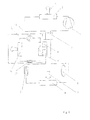
- FIG. 6 is a schematic illustration of a compression refrigeration circuit of an air conditioning unit for motor vehicles according to the invention including an additional heat exchanger coupled to a secondary cooling circuit with a cold store;
- FIG. 7 is a schematic illustration of compression refrigeration circuit of an air conditioning unit for motor vehicles according to the invention including an additional heat exchanger alternatively positioned, in contact with a thermoelectric cooling element; and
- FIG. 8 is a compression refrigeration circuit of an air conditioning unit for motor vehicles according to the invention including an additional heat exchanger alternatively positioned coupled to another compression circuit.
- FIG. 1 shows a conventional compression refrigeration circuit of an air conditioning unit for motor vehicles.
- This circuit includes a compressor 1 , a heat-delivering heat exchanger 2 , i. e. a heat exchanger in form of a condenser, or gas cooler, respectively, an expansion element 3 , and a heat-absorbing heat exchanger 4 , for example in form of an evaporator.
- a refrigerant circulates in the compression refrigeration circuit, the refrigerant continuously changing its temperature and/or pressure with phase transitions being possible.
- the heat-absorbing heat exchanger 4 is passed by the refrigerant at lower pressure while absorbing heat from the air surrounding it that is to be cooled.
- the absorbed heat leads to evaporation and/or heating of the refrigerant.
- the gaseous refrigerant is then passed through the compressor 1 , whereby the pressure and temperature of the refrigerant increase.
- the compressed hot refrigerant is directed to the heat-delivering heat exchanger 2 , where a portion of the heat energy is released to the ambient air so that the enthalpy of the compressed refrigerant reduces.
- the compressed refrigerant is then directed to the expansion element 3 and expanded so that its pressure and temperature decrease. At this state the expanded cold refrigerant is again led into the heat-absorbing heat exchanger 4 .
- an internal heat exchanger 5 is integrated, preferably passed counter currently.
- the refrigerant is led into the heat-absorbing heat exchanger 4 with an enthalpy as low as possible.
- the heat delivered by the heat-delivering heat exchanger 2 is not sufficient to ensure at certain operational pressures a sufficiently low refrigerant enthalpy at the outlet of the expansion element 3 .
- an accumulator 6 is shown.
- the accumulator 6 can also be combined with the internal heat exchanger 5 to form one component. Air is directed to both heat exchangers 2 , 4 , which is symbolized by arrows. One arrow marks an air flow 7 that is to be cooled. The other arrow marks an ambient air flow 8 that is to remove heat from the heat-delivering heat exchanger 2 , causing cooling or condensation of the refrigerant.
- FIG. 2 shows a compression refrigeration circuit of an air conditioning unit for motor vehicles provided with an additional heat exchanger 9 switched in series downstream of a heat-delivering heat exchanger 2 , upstream of an expansion element 3 .
- the additional heat exchanger 9 is thermally coupled to a switchable heat sink, the action as heat sink elucidated by the heat flow 10 directed away from the compression refrigeration circuit of the air conditioning unit.
- the basic strategy of the solution according to the invention is outlined.
- the goal is to extract more heat when it is required, that is, when the cooling output of the heat-delivering heat exchanger 2 is too low.
- This function is taken over by the additional heat exchanger 9 , when required. It is carried out, according to the invention, directly downstream of the heat-delivering heat exchanger 2 , before the refrigerant enters the internal heat exchanger 5 .
- the demand for an additional reduction of the temperature of the refrigerant can be found out, for example, by measuring the temperature of the refrigerant after its exit from the heat-delivering heat exchanger 2 and possibly, by judgment of the temperature difference between the temperature of the refrigerant and the ambient temperature. Then, the controller can decide on putting the additional heat exchanger 9 into action. In this case, the heat sink on the secondary side of the additional heat exchanger 9 has to be activated.
- the heat sink on the secondary side of the additional heat exchanger 9 can be established in different ways.
- FIG. 3 shows a compression refrigeration circuit of an air conditioning unit according to the invention for motor vehicles provided with an additional heat exchanger 9 ′, 9 ′′ and coupled to a secondary cooling circuit 11
- the additional heat exchanger 9 ′, 9 ′′ on its primary side 9 ′ absorbs heat from the refrigerant and delivers the heat on its secondary side 9 ′′ to the secondary circuit 11
- the secondary circuit 11 is capable to deliver the absorbed heat to the ambience through another heat exchanger 12 , the position of which can be freely chosen.
- the functional principle of this embodiment is first of all based on that two heat-delivering heat exchangers 2 , 12 are provided, the positions of which ensure that the efficiency of the heat delivery to the surrounding air depends in varying manner on the actual boundary conditions.
- the airstream is sufficient, thermally almost unadulterated ambient air approaches the heat-delivering heat exchanger 2 in the compression refrigeration circuit, which results in an effective heat transfer. If the airstream diminishes, which can occur on slowing-down or at a halt of the vehicle, the temperature of the inflowing air due to proximity to hot assemblies in the engine compartment or the pavement which is possibly heated up, is no longer equal to the outside temperature, but is partly significantly higher. This problem will not occur at the heat-delivering heat exchanger 12 of the secondary cooling circuit 11 , if the position of the heat exchanger 12 ensures a sufficient distance to heated-up assemblies and/or the possibly heated up pavement and/or regions heated up by possible stagnation of flow.
- a heat-delivering heat exchanger 12 of the secondary cooling circuit 11 can be carried out when the recirculation of a cooling fluid in the secondary cooling circuit 11 is started by a switchable recirculation device 13 such as a recirculation pump, which corresponds to the activation of the heat sink at the additional heat exchanger 9 , due to the switchability according to the invention of the heat sink making the energy demand for operating the secondary cooling circuit 11 arise only if required.
- a switchable recirculation device 13 such as a recirculation pump
- ambient temperature of the refrigerant can be reached as the minimum.
- FIG. 4 represents a compression refrigeration circuit of an air conditioning unit according to the invention for motor vehicles provided with an additional heat exchanger 9 in contact to a thermoelectric element 14 used as cooling element In this way, an embodiment is created capable to cool the refrigerant even below the ambient temperature.
- thermoelectric elements The work of thermoelectric elements is based on the Seebeck effect. If a voltage is applied to thermoelectric elements, regions of different temperatures develop. This physical effect enables to directly generate cold from an electric current.
- the element works like an electrically driven unit that generates cold. It absorbs heat at a certain temperature and releases this heat to the ambience at a higher temperature level.
- the additional heat exchanger 9 is put into contact to a cold region 15 of the thermoelectric element 14 .
- the hot region 16 of the thermoelectric element 14 is positioned such that it can deliver heat to the ambient air. Therefore, the hot region 16 of the thermoelectric element 14 takes on a temperature near to the temperature of the ambience. If a voltage is applied, the temperature of the cold region 15 of the thermoelectric element 14 is accordingly decreased.
- thermoelectric element 14 creates a heat sink usable according to the invention for further cooling down the refrigerant in the compression refrigeration circuit after leaving the heat-delivering heat exchanger 2 .
- the embodiment of the invention can be established with several thermoelectric elements provided.
- thermoelectric elements enable to cool the refrigerant down to temperatures below the ambient temperature.
- the operation of thermoelectric elements requires electric energy, which is made available by the on-board power supply of motor vehicles.
- the switchability of electric energy also allows the heat sink to be established according to the invention switchable on as required in the compression refrigeration circuit of the air conditioning unit. This embodiment especially offers the advantage of easy retrofitting.
- Thermoelectric elements can easily be retrofitted in that they are attached to a refrigerant-containing piece of tube or a similar heat conducting component, intensifying heat dissipation to the ambience when accordingly controlled.
- Such retrofitting is, for example, advantageous where some vehicles are to be adapted to critical ambient conditions without being compelled to change the series production of the model involved.
- the advantage of easy retrofitting even of complete model series or mass-produced vehicles is preserved.
- FIG. 5 shows a compression refrigeration circuit of an air conditioning unit according to the invention for motor vehicles provided with an additional heat exchanger 9 ′, 9 ′′, coupled to a further compression refrigeration circuit 17 .
- This embodiment also enables to decrease the temperature of the refrigerant in the primary compression refrigeration circuit of the air conditioning unit after the exit of the refrigerant from the heat-delivering heat exchanger 2 to temperatures below ambient temperature.
- the further compression refrigeration circuit 17 is an additional circuit that, however, is totally decoupled with respect to fluid flow from the primary compression refrigeration circuit of the air conditioning unit.
- Important constituents of the further compression refrigeration circuit 17 are, in addition to the secondary side 9 ′′ of the heat exchanger over which coupling to the primary compression refrigeration circuit of the air conditioning unit is established, a compressor 18 , an expansion element 19 , and a further heat-delivering heat exchanger 20 , over which heat energy is dissipated to the ambience.
- the compressor 8 is electrically driven.
- the switchability of the compressor 18 also allows to establish, according to the invention, the additional heat sink to be switchable as required in the compression refrigeration circuit of the air conditioning unit.
- FIG. 6 shows a compression refrigeration circuit of an air conditioning unit according to the invention for motor vehicles provided with an additional heat exchanger 9 ′, 9 ′′, coupled to a secondary cooling circuit 21 that again is thermally coupled to a cold store 23 over a further heat exchanger 22 .
- the cold store is preferably designed as large-volume fluid circuit with at least one recirculation element 24 established as a pump, for example.
- the cold store 23 is directly thermally coupled to the primary compression refrigeration circuit of the air conditioning unit over a charging heat exchanger 25 , which is positioned in the primary compression refrigeration circuit, with respect to fluid flow, downstream of the heat-absorbing heat exchanger 4 .
- the cold store 23 At operational conditions that do not require the temperature of the cooling means to be decreased, the cold store 23 is then charged over the charging heat exchanger 25 that is thermally coupled to the compression refrigeration circuit. At operational conditions that do require the temperature of the cooling means to be decreased, the cold store 23 is then thermally coupled to the compression refrigeration circuit over the additional heat exchanger 9 ′, 9 ′′. In this way, at these operational states, the additional heat sink according to the invention is provided.
- the thermal coupling of the cold store 23 over the additional heat exchanger 9 ′, 9 ′′ to the compression refrigeration circuit is preferably established over the secondary cooling circuit 21 , which in this case arranges the thermal contact between the cold store 23 and the primary compression circuit of the air conditioning unit over a recirculating fluid.
- a cold store 23 is charged in those phases where the compression refrigeration process in the compression refrigeration circuit can be run optimally also without using the additional heat sink according to the invention and the conditions of heat delivery by the heat-delivering heat exchanger 2 are nearly optimal, or at least convenient.
- the refrigerant Downstream of the heat-absorbing heat exchanger 4 the refrigerant hereby passes a further heat exchanger, the charging heat exchanger 25 .
- the heat-absorbing heat exchanger 4 is an evaporator, the refrigerant is simply continued to be evaporated in the charging heat exchanger 25 , thereby extracting a corresponding amount of heat from the working medium on the secondary side of the charging heat exchanger 25 , i. e. the fluid in the cold store 23 .
- the so cooled working medium in the cold store 23 is therefore capable to absorb if required a similar amount of heat from the secondary cooling circuit 21 , forming the base of a “charged” cold store.
- the process described here is typically operated in cyclic manner.
- FIG. 7 shows a compression refrigeration circuit of an air conditioning unit according to the invention for motor vehicles provided with an alternatively positioned additional heat exchanger 9 that is in contact to a thermoelectric element 14 .
- additional heat exchanger 9 that is in contact to a thermoelectric element 14 .
- FIG. 8 shows a compression refrigeration circuit of an air conditioning unit according to the invention for motor vehicles provided with an alternatively positioned additional heat exchanger 9 ′, 9 ′′, coupled to a further compression refrigeration circuit 17 .
- additional heat exchanger 9 ′, 9 ′′ in direction of flow is exchanged. Otherwise, the description of FIG. 5 applies.
Landscapes
- Engineering & Computer Science (AREA)
- Physics & Mathematics (AREA)
- Mechanical Engineering (AREA)
- Thermal Sciences (AREA)
- General Engineering & Computer Science (AREA)
- Air-Conditioning For Vehicles (AREA)
Applications Claiming Priority (3)
| Application Number | Priority Date | Filing Date | Title |
|---|---|---|---|
| DE102007035110A DE102007035110A1 (de) | 2007-07-20 | 2007-07-20 | Klimaanlage für Kraftfahrzeuge und Verfahren zu ihrem Betrieb |
| DE102007035110.2-16 | 2007-07-20 | ||
| DE102007035110 | 2007-07-20 |
Publications (2)
| Publication Number | Publication Date |
|---|---|
| US20090019861A1 US20090019861A1 (en) | 2009-01-22 |
| US8037698B2 true US8037698B2 (en) | 2011-10-18 |
Family
ID=40149129
Family Applications (1)
| Application Number | Title | Priority Date | Filing Date |
|---|---|---|---|
| US12/175,040 Expired - Fee Related US8037698B2 (en) | 2007-07-20 | 2008-07-17 | Air conditioning unit for motor vehicles and method for its operation |
Country Status (3)
| Country | Link |
|---|---|
| US (1) | US8037698B2 (ja) |
| JP (1) | JP2009040407A (ja) |
| DE (1) | DE102007035110A1 (ja) |
Cited By (6)
| Publication number | Priority date | Publication date | Assignee | Title |
|---|---|---|---|---|
| US20160332508A1 (en) * | 2014-01-22 | 2016-11-17 | Hanon Systems | Air conditioner system for vehicle |
| US20170246934A1 (en) * | 2014-07-29 | 2017-08-31 | Hanon Systems | Air conditioner system for vehicle |
| US20180306453A1 (en) * | 2012-09-13 | 2018-10-25 | Alstom Transport Technologies | Air-Conditioning Device, in particular for a Rail Vehicle |
| US10343781B2 (en) | 2013-04-03 | 2019-07-09 | Airbus Operations Gmb | Aircraft cooling system |
| US10837684B2 (en) | 2018-04-23 | 2020-11-17 | Dell Products, L.P. | Automatic controls method for adding the optimal amount of refrigerant to a direct expansion cooling system |
| SE2450469A1 (en) * | 2024-04-30 | 2025-10-31 | Ola Lindborg | Refrigeration circuit |
Families Citing this family (37)
| Publication number | Priority date | Publication date | Assignee | Title |
|---|---|---|---|---|
| JP2011027190A (ja) * | 2009-07-27 | 2011-02-10 | Chubu Electric Power Co Inc | 伸縮継手 |
| US8365539B2 (en) * | 2010-02-12 | 2013-02-05 | Massachusetts Institute Of Technology | System and method for thermal process including a thermoelectric heat pump and internal heat exchanger |
| SE534908C2 (sv) * | 2010-06-11 | 2012-02-14 | Scania Cv Ab | Kylmediekrets för fordon |
| JP5685886B2 (ja) * | 2010-10-22 | 2015-03-18 | ダイキン工業株式会社 | 給湯装置 |
| EP2664867A4 (en) * | 2010-10-22 | 2018-07-11 | Valeo Japan Co., Ltd. | Refrigeration cycle and condenser with supercooling unit |
| CN102452297B (zh) * | 2010-10-29 | 2014-07-09 | 杭州三花研究院有限公司 | 电动汽车及其热管理系统 |
| JPWO2012066763A1 (ja) * | 2010-11-15 | 2014-05-12 | 三菱電機株式会社 | 冷凍装置 |
| DE102010056283A1 (de) * | 2010-12-24 | 2012-06-28 | Volkswagen Ag | Wärmeübertragungssystem |
| JP6141195B2 (ja) | 2011-01-20 | 2017-06-07 | サウジ アラビアン オイル カンパニー | 車両内燃機関の排気ガスからのco2の車載での回収及び貯蔵のための廃熱を利用する膜分離方法及びシステム |
| KR101739167B1 (ko) * | 2011-01-20 | 2017-06-08 | 사우디 아라비안 오일 컴퍼니 | 자동차 내연기관 배기 가스로부터의 co2의 온-보드 회수 및 저장을 위해 폐열을 활용하는 직접 치밀화 방법 및 시스템 |
| WO2012100165A1 (en) | 2011-01-20 | 2012-07-26 | Saudi Arabian Oil Company | Οn-board recovery and storage of c02 from motor vehicle exhaust gases |
| JP2013002737A (ja) * | 2011-06-16 | 2013-01-07 | Mitsubishi Electric Corp | 冷凍サイクル装置 |
| US9134053B2 (en) * | 2011-08-23 | 2015-09-15 | B/E Aerospace, Inc. | Vehicle refrigerator having a liquid line subcooled vapor cycle system |
| US9310140B2 (en) | 2012-02-07 | 2016-04-12 | Rebound Technologies, Inc. | Methods, systems, and devices for thermal enhancement |
| US10352606B2 (en) * | 2012-04-27 | 2019-07-16 | Carrier Corporation | Cooling system |
| US9879888B2 (en) | 2012-10-30 | 2018-01-30 | Lennox Industries Inc. | Auxiliary heat exchanger having fluid retention member for evaporative cooling |
| KR101438949B1 (ko) * | 2012-12-14 | 2014-09-11 | 현대자동차주식회사 | 전기차량의 공조장치 |
| DE102013203240A1 (de) * | 2013-02-27 | 2014-08-28 | Siemens Aktiengesellschaft | Kältemaschine und Verfahren zum Betreiben einer Kältemaschine |
| DE102013211177A1 (de) * | 2013-06-14 | 2014-12-18 | Airbus Operations Gmbh | Flugzeugkühlsystem und Verfahren zum Betreiben eines Flugzeugkühlsystems |
| DE102013021177A1 (de) * | 2013-12-17 | 2015-06-18 | Alessandro Plog | Thermoelektrischer-Unterkühler |
| DE102014205005B4 (de) | 2014-03-18 | 2025-12-18 | Ford Global Technologies, Llc | Verfahren zum Betrieb der Klimaanlage eines Kraftfahrzeugs, Klimaanlage für ein Kraftfahrzeug |
| US10995993B2 (en) | 2014-09-27 | 2021-05-04 | Rebound Technologies, Inc. | Thermal recuperation methods, systems, and devices |
| FR3030700B1 (fr) * | 2014-12-18 | 2019-03-22 | Valeo Systemes Thermiques | Circuit de climatisation de vehicule automobile |
| WO2017010239A1 (ja) * | 2015-07-14 | 2017-01-19 | 株式会社デンソー | 冷凍サイクル装置 |
| JP6380455B2 (ja) * | 2015-07-14 | 2018-08-29 | 株式会社デンソー | 冷凍サイクル装置 |
| EP3418087B1 (en) * | 2017-02-03 | 2020-03-04 | AGCO International GmbH | An agricultural vehicle having improved energy efficiency |
| US10584904B2 (en) * | 2017-03-27 | 2020-03-10 | Rebound Technologies, Inc. | Cycle enhancement methods, systems, and devices |
| CA3091280A1 (en) | 2018-02-23 | 2019-08-29 | Rebound Technologies, Inc. | Freeze point suppression cycle control systems, methods, and devices. |
| CN108826766A (zh) * | 2018-04-28 | 2018-11-16 | 珠海格力电器股份有限公司 | 一种空调系统及其控制方法 |
| WO2020132467A1 (en) | 2018-12-20 | 2020-06-25 | Rebound Technologies, Inc. | Thermo-chemical recuperation systems, devices, and methods |
| FR3111097A1 (fr) * | 2020-06-08 | 2021-12-10 | Valeo Systemes Thermiques | Système de conditionnement thermique pour véhicule automobile |
| EP4165352A4 (en) * | 2020-06-15 | 2024-08-07 | DTP Thermoelectrics LLC | THERMOELECTRICALLY ENHANCED HYBRID HEAT PUMP SYSTEMS |
| CN114274738A (zh) * | 2020-09-28 | 2022-04-05 | 冷王公司 | 用于在一段延长的时间段内在超低温度下保存货物的方法和系统 |
| DE102020134599A1 (de) | 2020-12-22 | 2022-06-23 | Universität Stuttgart, Körperschaft Des Öffentlichen Rechts | Wärmetauscher, Wärmetauschernetzwerk und Wärmetauschverfahren |
| KR102488817B1 (ko) * | 2021-07-20 | 2023-01-18 | 한국생산기술연구원 | 예비 냉각을 포함하는 고효율 초저온 혼합냉매 냉각 장치 및 이를 이용한 냉각 방법 |
| DE102021126963A1 (de) * | 2021-10-18 | 2023-04-20 | Thermo Electron Led Gmbh | Kühlsystem |
| KR102712189B1 (ko) * | 2022-04-27 | 2024-10-02 | 한국생산기술연구원 | 극저온 냉동 장치 |
Citations (31)
| Publication number | Priority date | Publication date | Assignee | Title |
|---|---|---|---|---|
| US5046325A (en) * | 1988-06-30 | 1991-09-10 | Kabushiki Kaisha Toshiba | Refrigerating circuit apparatus with two stage compressor and heat storage tank |
| US5406805A (en) * | 1993-11-12 | 1995-04-18 | University Of Maryland | Tandem refrigeration system |
| US5622055A (en) * | 1995-03-22 | 1997-04-22 | Martin Marietta Energy Systems, Inc. | Liquid over-feeding refrigeration system and method with integrated accumulator-expander-heat exchanger |
| US5899091A (en) * | 1997-12-15 | 1999-05-04 | Carrier Corporation | Refrigeration system with integrated economizer/oil cooler |
| US5921092A (en) * | 1998-03-16 | 1999-07-13 | Hussmann Corporation | Fluid defrost system and method for secondary refrigeration systems |
| US6185957B1 (en) * | 1999-09-07 | 2001-02-13 | Modine Manufacturing Company | Combined evaporator/accumulator/suctionline heat exchanger |
| US6233969B1 (en) * | 1998-12-09 | 2001-05-22 | Denso Corporation | Decompression device-integrated heat exchanger for refrigerant cycle |
| DE10060114A1 (de) | 1999-12-09 | 2001-06-13 | Valeo Climatisation | Klimakreis, insbesondere für ein Kraftfahrzeug |
| US6260367B1 (en) * | 1997-12-26 | 2001-07-17 | Zexel Corporation | Refrigerating cycle |
| US20010017037A1 (en) * | 2000-02-28 | 2001-08-30 | Martin Kerron James | Thermostat controller |
| US6386277B1 (en) * | 2001-04-24 | 2002-05-14 | Modine Manufacturing Company | Heat exchanger header construction |
| US6467300B1 (en) * | 2001-03-27 | 2002-10-22 | John O. Noble, III | Refrigerated intercooler |
| DE10231645A1 (de) | 2001-07-12 | 2003-01-30 | Calsonic Kansei Corp | Kühlkreislauf |
| US6523360B2 (en) * | 2000-10-30 | 2003-02-25 | Calsonic Kansei Corporation | Cooling cycle and control method thereof |
| DE10159148A1 (de) | 2001-12-01 | 2003-06-12 | Bosch Gmbh Robert | Klimaanlage |
| US6606867B1 (en) * | 2000-11-15 | 2003-08-19 | Carrier Corporation | Suction line heat exchanger storage tank for transcritical cycles |
| US6662576B1 (en) * | 2002-09-23 | 2003-12-16 | Vai Holdings Llc | Refrigeration system with de-superheating bypass |
| US6701723B1 (en) * | 2002-09-26 | 2004-03-09 | Carrier Corporation | Humidity control and efficiency enhancement in vapor compression system |
| DE10258618B3 (de) | 2002-12-16 | 2004-06-24 | Daimlerchrysler Ag | Klimaanlage, insbesondere für Kraftfahrzeuge |
| US6786057B2 (en) * | 2000-10-12 | 2004-09-07 | Valeo Climatisation | Vehicle air conditioning device using a supercritical cycle |
| US20050028545A1 (en) * | 1998-10-08 | 2005-02-10 | Hebert Thomas H. | Building exhaust and air conditioner condensate (and/or other water source) evaporative refrigerant subcool/precool system and method therefor |
| US6901763B2 (en) * | 2003-06-24 | 2005-06-07 | Modine Manufacturing Company | Refrigeration system |
| WO2005059449A1 (en) | 2003-12-10 | 2005-06-30 | Carrier Corporation | Refrigerant system performance enhancement by use of additonal heat exchanger |
| US6923019B2 (en) * | 2002-10-17 | 2005-08-02 | Denso Corporation | Heat exchanger |
| US6923011B2 (en) * | 2003-09-02 | 2005-08-02 | Tecumseh Products Company | Multi-stage vapor compression system with intermediate pressure vessel |
| US20060137366A1 (en) * | 2004-12-27 | 2006-06-29 | Carrier Corporation | Automatic refrigerant charging apparatus |
| US7076964B2 (en) * | 2001-10-03 | 2006-07-18 | Denso Corporation | Super-critical refrigerant cycle system and water heater using the same |
| US7131291B2 (en) * | 2001-09-03 | 2006-11-07 | Sinvent As | Compression system for cooling and heating purposes |
| US20070074536A1 (en) * | 2002-11-11 | 2007-04-05 | Cheolho Bai | Refrigeration system with bypass subcooling and component size de-optimization |
| US20070101737A1 (en) * | 2005-11-09 | 2007-05-10 | Masao Akei | Refrigeration system including thermoelectric heat recovery and actuation |
| US7334430B2 (en) * | 2004-12-24 | 2008-02-26 | Denso Corporation | Refrigerating cycle |
Family Cites Families (7)
| Publication number | Priority date | Publication date | Assignee | Title |
|---|---|---|---|---|
| JPS61250460A (ja) * | 1985-04-26 | 1986-11-07 | 富士重工業株式会社 | 冷房装置 |
| DE19630431B4 (de) * | 1996-07-27 | 2009-06-10 | Behr Gmbh & Co. Kg | Klimaanlage für ein Kraftfahrzeug |
| JP2000074514A (ja) * | 1998-09-03 | 2000-03-14 | Hitachi Ltd | 蓄電式空気調和装置及びそれに用いられる冷熱源装置 |
| JP3417389B2 (ja) * | 2000-07-24 | 2003-06-16 | トヨタ自動車株式会社 | 車両のエネルギー蓄積装置用制御装置 |
| DE10242369B4 (de) * | 2002-09-12 | 2007-09-13 | Webasto Ag | Klimatisierungssystem für ein Kraftfahrzeug, insbesondere ein Hybridfahrzeug |
| JP4062129B2 (ja) * | 2003-03-05 | 2008-03-19 | 株式会社デンソー | 蒸気圧縮式冷凍機 |
| DE102005021396A1 (de) * | 2005-05-04 | 2006-11-09 | Behr Gmbh & Co. Kg | Vorrichtung zur Luftkonditionierung für ein Kraftfahrzeug |
-
2007
- 2007-07-20 DE DE102007035110A patent/DE102007035110A1/de not_active Withdrawn
-
2008
- 2008-07-17 US US12/175,040 patent/US8037698B2/en not_active Expired - Fee Related
- 2008-07-18 JP JP2008209353A patent/JP2009040407A/ja active Pending
Patent Citations (32)
| Publication number | Priority date | Publication date | Assignee | Title |
|---|---|---|---|---|
| US5046325A (en) * | 1988-06-30 | 1991-09-10 | Kabushiki Kaisha Toshiba | Refrigerating circuit apparatus with two stage compressor and heat storage tank |
| US5406805A (en) * | 1993-11-12 | 1995-04-18 | University Of Maryland | Tandem refrigeration system |
| US5622055A (en) * | 1995-03-22 | 1997-04-22 | Martin Marietta Energy Systems, Inc. | Liquid over-feeding refrigeration system and method with integrated accumulator-expander-heat exchanger |
| US5899091A (en) * | 1997-12-15 | 1999-05-04 | Carrier Corporation | Refrigeration system with integrated economizer/oil cooler |
| US6260367B1 (en) * | 1997-12-26 | 2001-07-17 | Zexel Corporation | Refrigerating cycle |
| US5921092A (en) * | 1998-03-16 | 1999-07-13 | Hussmann Corporation | Fluid defrost system and method for secondary refrigeration systems |
| US20050028545A1 (en) * | 1998-10-08 | 2005-02-10 | Hebert Thomas H. | Building exhaust and air conditioner condensate (and/or other water source) evaporative refrigerant subcool/precool system and method therefor |
| US6233969B1 (en) * | 1998-12-09 | 2001-05-22 | Denso Corporation | Decompression device-integrated heat exchanger for refrigerant cycle |
| US6185957B1 (en) * | 1999-09-07 | 2001-02-13 | Modine Manufacturing Company | Combined evaporator/accumulator/suctionline heat exchanger |
| DE10060114A1 (de) | 1999-12-09 | 2001-06-13 | Valeo Climatisation | Klimakreis, insbesondere für ein Kraftfahrzeug |
| US20010017037A1 (en) * | 2000-02-28 | 2001-08-30 | Martin Kerron James | Thermostat controller |
| US6786057B2 (en) * | 2000-10-12 | 2004-09-07 | Valeo Climatisation | Vehicle air conditioning device using a supercritical cycle |
| US6523360B2 (en) * | 2000-10-30 | 2003-02-25 | Calsonic Kansei Corporation | Cooling cycle and control method thereof |
| US6606867B1 (en) * | 2000-11-15 | 2003-08-19 | Carrier Corporation | Suction line heat exchanger storage tank for transcritical cycles |
| US6467300B1 (en) * | 2001-03-27 | 2002-10-22 | John O. Noble, III | Refrigerated intercooler |
| US6386277B1 (en) * | 2001-04-24 | 2002-05-14 | Modine Manufacturing Company | Heat exchanger header construction |
| DE10231645A1 (de) | 2001-07-12 | 2003-01-30 | Calsonic Kansei Corp | Kühlkreislauf |
| US7131291B2 (en) * | 2001-09-03 | 2006-11-07 | Sinvent As | Compression system for cooling and heating purposes |
| US7076964B2 (en) * | 2001-10-03 | 2006-07-18 | Denso Corporation | Super-critical refrigerant cycle system and water heater using the same |
| DE10159148A1 (de) | 2001-12-01 | 2003-06-12 | Bosch Gmbh Robert | Klimaanlage |
| US6662576B1 (en) * | 2002-09-23 | 2003-12-16 | Vai Holdings Llc | Refrigeration system with de-superheating bypass |
| US6701723B1 (en) * | 2002-09-26 | 2004-03-09 | Carrier Corporation | Humidity control and efficiency enhancement in vapor compression system |
| US6923019B2 (en) * | 2002-10-17 | 2005-08-02 | Denso Corporation | Heat exchanger |
| US20070074536A1 (en) * | 2002-11-11 | 2007-04-05 | Cheolho Bai | Refrigeration system with bypass subcooling and component size de-optimization |
| DE10258618B3 (de) | 2002-12-16 | 2004-06-24 | Daimlerchrysler Ag | Klimaanlage, insbesondere für Kraftfahrzeuge |
| US6901763B2 (en) * | 2003-06-24 | 2005-06-07 | Modine Manufacturing Company | Refrigeration system |
| US6923011B2 (en) * | 2003-09-02 | 2005-08-02 | Tecumseh Products Company | Multi-stage vapor compression system with intermediate pressure vessel |
| WO2005059449A1 (en) | 2003-12-10 | 2005-06-30 | Carrier Corporation | Refrigerant system performance enhancement by use of additonal heat exchanger |
| US7334430B2 (en) * | 2004-12-24 | 2008-02-26 | Denso Corporation | Refrigerating cycle |
| US20060137366A1 (en) * | 2004-12-27 | 2006-06-29 | Carrier Corporation | Automatic refrigerant charging apparatus |
| US20070101737A1 (en) * | 2005-11-09 | 2007-05-10 | Masao Akei | Refrigeration system including thermoelectric heat recovery and actuation |
| US7240494B2 (en) * | 2005-11-09 | 2007-07-10 | Emerson Climate Technologies, Inc. | Vapor compression circuit and method including a thermoelectric device |
Cited By (8)
| Publication number | Priority date | Publication date | Assignee | Title |
|---|---|---|---|---|
| US20180306453A1 (en) * | 2012-09-13 | 2018-10-25 | Alstom Transport Technologies | Air-Conditioning Device, in particular for a Rail Vehicle |
| US10343781B2 (en) | 2013-04-03 | 2019-07-09 | Airbus Operations Gmb | Aircraft cooling system |
| US20160332508A1 (en) * | 2014-01-22 | 2016-11-17 | Hanon Systems | Air conditioner system for vehicle |
| US10059173B2 (en) * | 2014-01-22 | 2018-08-28 | Hanon Systems | Air conditioner system for vehicle |
| US20170246934A1 (en) * | 2014-07-29 | 2017-08-31 | Hanon Systems | Air conditioner system for vehicle |
| US10766340B2 (en) * | 2014-07-29 | 2020-09-08 | Hanon Systems | Air conditioner system for vehicle |
| US10837684B2 (en) | 2018-04-23 | 2020-11-17 | Dell Products, L.P. | Automatic controls method for adding the optimal amount of refrigerant to a direct expansion cooling system |
| SE2450469A1 (en) * | 2024-04-30 | 2025-10-31 | Ola Lindborg | Refrigeration circuit |
Also Published As
| Publication number | Publication date |
|---|---|
| JP2009040407A (ja) | 2009-02-26 |
| DE102007035110A1 (de) | 2009-01-22 |
| US20090019861A1 (en) | 2009-01-22 |
Similar Documents
| Publication | Publication Date | Title |
|---|---|---|
| US8037698B2 (en) | Air conditioning unit for motor vehicles and method for its operation | |
| CN111132860B (zh) | 制冷循环装置 | |
| US9925845B2 (en) | Heat exchange system | |
| CN105848937B (zh) | 车辆用空调装置 | |
| CN110576720B (zh) | 机动车辆的空调系统和用于运行空调系统的方法 | |
| JP7251229B2 (ja) | 車載温調装置 | |
| KR102039163B1 (ko) | 자동차용 히트펌프 | |
| JP6167892B2 (ja) | 車両用空調装置 | |
| CN103568777B (zh) | 用于机动车辆中的热分配的装置和方法 | |
| US7841431B2 (en) | Electric vehicle thermal management system | |
| US20170197490A1 (en) | Refrigeration cycle device | |
| CN108136874B (zh) | 车辆用热管理装置 | |
| JP5979078B2 (ja) | 温度調節装置 | |
| KR102091809B1 (ko) | 자동차용 히트펌프 | |
| KR20180122272A (ko) | 자동차의 공조 시스템 및 공조 시스템의 작동 방법 | |
| CN107206865A (zh) | 车辆用热管理系统 | |
| CN102563943A (zh) | 汽车空调设备的制冷剂循环回路 | |
| JP2009190579A (ja) | 空気調和システム | |
| CN102906528A (zh) | 热交换器 | |
| CN221090418U (zh) | 间接式热泵热管理系统和车辆 | |
| WO2015097987A1 (ja) | 車両用空調装置 | |
| CN111902300A (zh) | 用于炎热气候地区的电动车辆热管理系统 | |
| US20110100038A1 (en) | Refrigerant Circuit And Method For Operating A Refrigerant Circuit | |
| KR102039170B1 (ko) | 자동차용 히트펌프 | |
| US20090191804A1 (en) | Heating, ventilating, and air conditioning system having a thermal energy exchanger |
Legal Events
| Date | Code | Title | Description |
|---|---|---|---|
| AS | Assignment |
Owner name: VISTEON GLOBAL TECHNOLOGIES, INC., MICHIGAN Free format text: ASSIGNMENT OF ASSIGNORS INTEREST;ASSIGNORS:HECKT, ROMAN, DR.;GRAAF, MARC;HAAS, TOBIAS;SIGNING DATES FROM 20080811 TO 20080812;REEL/FRAME:021564/0898 Owner name: VISTEON GLOBAL TECHNOLOGIES, INC., MICHIGAN Free format text: ASSIGNMENT OF ASSIGNORS INTEREST;ASSIGNORS:HECKT, ROMAN, DR.;GRAAF, MARC;HAAS, TOBIAS;REEL/FRAME:021564/0898;SIGNING DATES FROM 20080811 TO 20080812 |
|
| AS | Assignment |
Owner name: WILMINGTON TRUST FSB, AS ADMINISTRATIVE AGENT, MIN Free format text: GRANT OF SECURITY INTEREST IN PATENT RIGHTS;ASSIGNOR:VISTEON GLOBAL TECHNOLOGIES, INC.;REEL/FRAME:022619/0938 Effective date: 20090430 Owner name: WILMINGTON TRUST FSB, AS ADMINISTRATIVE AGENT,MINN Free format text: GRANT OF SECURITY INTEREST IN PATENT RIGHTS;ASSIGNOR:VISTEON GLOBAL TECHNOLOGIES, INC.;REEL/FRAME:022619/0938 Effective date: 20090430 |
|
| AS | Assignment |
Owner name: VISTEON GLOBAL TECHNOLOGIES, INC., MICHIGAN Free format text: RELEASE BY SECURED PARTY AGAINST SECURITY INTEREST IN PATENTS RECORDED AT REEL 022619 FRAME 0938;ASSIGNOR:WILMINGTON TRUST FSB;REEL/FRAME:025095/0466 Effective date: 20101001 |
|
| AS | Assignment |
Owner name: MORGAN STANLEY SENIOR FUNDING, INC., AS AGENT, NEW YORK Free format text: SECURITY AGREEMENT (REVOLVER);ASSIGNORS:VISTEON CORPORATION;VC AVIATION SERVICES, LLC;VISTEON ELECTRONICS CORPORATION;AND OTHERS;REEL/FRAME:025238/0298 Effective date: 20101001 Owner name: MORGAN STANLEY SENIOR FUNDING, INC., AS AGENT, NEW YORK Free format text: SECURITY AGREEMENT;ASSIGNORS:VISTEON CORPORATION;VC AVIATION SERVICES, LLC;VISTEON ELECTRONICS CORPORATION;AND OTHERS;REEL/FRAME:025241/0317 Effective date: 20101007 Owner name: MORGAN STANLEY SENIOR FUNDING, INC., AS AGENT, NEW Free format text: SECURITY AGREEMENT (REVOLVER);ASSIGNORS:VISTEON CORPORATION;VC AVIATION SERVICES, LLC;VISTEON ELECTRONICS CORPORATION;AND OTHERS;REEL/FRAME:025238/0298 Effective date: 20101001 Owner name: MORGAN STANLEY SENIOR FUNDING, INC., AS AGENT, NEW Free format text: SECURITY AGREEMENT;ASSIGNORS:VISTEON CORPORATION;VC AVIATION SERVICES, LLC;VISTEON ELECTRONICS CORPORATION;AND OTHERS;REEL/FRAME:025241/0317 Effective date: 20101007 |
|
| AS | Assignment |
Owner name: VISTEON EUROPEAN HOLDING, INC., MICHIGAN Free format text: RELEASE BY SECURED PARTY AGAINST SECURITY INTEREST IN PATENTS ON REEL 025241 FRAME 0317;ASSIGNOR:MORGAN STANLEY SENIOR FUNDING, INC.;REEL/FRAME:026178/0412 Effective date: 20110406 Owner name: VISTEON GLOBAL TECHNOLOGIES, INC., MICHIGAN Free format text: RELEASE BY SECURED PARTY AGAINST SECURITY INTEREST IN PATENTS ON REEL 025241 FRAME 0317;ASSIGNOR:MORGAN STANLEY SENIOR FUNDING, INC.;REEL/FRAME:026178/0412 Effective date: 20110406 Owner name: VC AVIATION SERVICES, LLC, MICHIGAN Free format text: RELEASE BY SECURED PARTY AGAINST SECURITY INTEREST IN PATENTS ON REEL 025241 FRAME 0317;ASSIGNOR:MORGAN STANLEY SENIOR FUNDING, INC.;REEL/FRAME:026178/0412 Effective date: 20110406 Owner name: VISTEON ELECTRONICS CORPORATION, MICHIGAN Free format text: RELEASE BY SECURED PARTY AGAINST SECURITY INTEREST IN PATENTS ON REEL 025241 FRAME 0317;ASSIGNOR:MORGAN STANLEY SENIOR FUNDING, INC.;REEL/FRAME:026178/0412 Effective date: 20110406 Owner name: VISTEON SYSTEMS, LLC, MICHIGAN Free format text: RELEASE BY SECURED PARTY AGAINST SECURITY INTEREST IN PATENTS ON REEL 025241 FRAME 0317;ASSIGNOR:MORGAN STANLEY SENIOR FUNDING, INC.;REEL/FRAME:026178/0412 Effective date: 20110406 Owner name: VISTEON INTERNATIONAL HOLDINGS, INC., MICHIGAN Free format text: RELEASE BY SECURED PARTY AGAINST SECURITY INTEREST IN PATENTS ON REEL 025241 FRAME 0317;ASSIGNOR:MORGAN STANLEY SENIOR FUNDING, INC.;REEL/FRAME:026178/0412 Effective date: 20110406 Owner name: VISTEON CORPORATION, MICHIGAN Free format text: RELEASE BY SECURED PARTY AGAINST SECURITY INTEREST IN PATENTS ON REEL 025241 FRAME 0317;ASSIGNOR:MORGAN STANLEY SENIOR FUNDING, INC.;REEL/FRAME:026178/0412 Effective date: 20110406 Owner name: VISTEON GLOBAL TREASURY, INC., MICHIGAN Free format text: RELEASE BY SECURED PARTY AGAINST SECURITY INTEREST IN PATENTS ON REEL 025241 FRAME 0317;ASSIGNOR:MORGAN STANLEY SENIOR FUNDING, INC.;REEL/FRAME:026178/0412 Effective date: 20110406 Owner name: VISTEON INTERNATIONAL BUSINESS DEVELOPMENT, INC., Free format text: RELEASE BY SECURED PARTY AGAINST SECURITY INTEREST IN PATENTS ON REEL 025241 FRAME 0317;ASSIGNOR:MORGAN STANLEY SENIOR FUNDING, INC.;REEL/FRAME:026178/0412 Effective date: 20110406 Owner name: VISTEON INTERNATIONAL BUSINESS DEVELOPMENT, INC., MICHIGAN Free format text: RELEASE BY SECURED PARTY AGAINST SECURITY INTEREST IN PATENTS ON REEL 025241 FRAME 0317;ASSIGNOR:MORGAN STANLEY SENIOR FUNDING, INC.;REEL/FRAME:026178/0412 Effective date: 20110406 |
|
| ZAAA | Notice of allowance and fees due |
Free format text: ORIGINAL CODE: NOA |
|
| ZAAB | Notice of allowance mailed |
Free format text: ORIGINAL CODE: MN/=. |
|
| STCF | Information on status: patent grant |
Free format text: PATENTED CASE |
|
| AS | Assignment |
Owner name: HALLA VISTEON CLIMATE CONTROL CORPORATION, KOREA, Free format text: ASSIGNMENT OF ASSIGNORS INTEREST;ASSIGNOR:VISTEON GLOBAL TECHNOLOGIES, INC.;REEL/FRAME:030935/0958 Effective date: 20130726 |
|
| AS | Assignment |
Owner name: VISTEON INTERNATIONAL HOLDINGS, INC., MICHIGAN Free format text: RELEASE OF SECURITY INTEREST IN INTELLECTUAL PROPERTY;ASSIGNOR:MORGAN STANLEY SENIOR FUNDING, INC.;REEL/FRAME:033107/0717 Effective date: 20140409 Owner name: VISTEON GLOBAL TREASURY, INC., MICHIGAN Free format text: RELEASE OF SECURITY INTEREST IN INTELLECTUAL PROPERTY;ASSIGNOR:MORGAN STANLEY SENIOR FUNDING, INC.;REEL/FRAME:033107/0717 Effective date: 20140409 Owner name: VISTEON SYSTEMS, LLC, MICHIGAN Free format text: RELEASE OF SECURITY INTEREST IN INTELLECTUAL PROPERTY;ASSIGNOR:MORGAN STANLEY SENIOR FUNDING, INC.;REEL/FRAME:033107/0717 Effective date: 20140409 Owner name: VC AVIATION SERVICES, LLC, MICHIGAN Free format text: RELEASE OF SECURITY INTEREST IN INTELLECTUAL PROPERTY;ASSIGNOR:MORGAN STANLEY SENIOR FUNDING, INC.;REEL/FRAME:033107/0717 Effective date: 20140409 Owner name: VISTEON GLOBAL TECHNOLOGIES, INC., MICHIGAN Free format text: RELEASE OF SECURITY INTEREST IN INTELLECTUAL PROPERTY;ASSIGNOR:MORGAN STANLEY SENIOR FUNDING, INC.;REEL/FRAME:033107/0717 Effective date: 20140409 Owner name: VISTEON CORPORATION, MICHIGAN Free format text: RELEASE OF SECURITY INTEREST IN INTELLECTUAL PROPERTY;ASSIGNOR:MORGAN STANLEY SENIOR FUNDING, INC.;REEL/FRAME:033107/0717 Effective date: 20140409 Owner name: VISTEON ELECTRONICS CORPORATION, MICHIGAN Free format text: RELEASE OF SECURITY INTEREST IN INTELLECTUAL PROPERTY;ASSIGNOR:MORGAN STANLEY SENIOR FUNDING, INC.;REEL/FRAME:033107/0717 Effective date: 20140409 Owner name: VISTEON EUROPEAN HOLDINGS, INC., MICHIGAN Free format text: RELEASE OF SECURITY INTEREST IN INTELLECTUAL PROPERTY;ASSIGNOR:MORGAN STANLEY SENIOR FUNDING, INC.;REEL/FRAME:033107/0717 Effective date: 20140409 Owner name: VISTEON INTERNATIONAL BUSINESS DEVELOPMENT, INC., Free format text: RELEASE OF SECURITY INTEREST IN INTELLECTUAL PROPERTY;ASSIGNOR:MORGAN STANLEY SENIOR FUNDING, INC.;REEL/FRAME:033107/0717 Effective date: 20140409 Owner name: VISTEON INTERNATIONAL BUSINESS DEVELOPMENT, INC., MICHIGAN Free format text: RELEASE OF SECURITY INTEREST IN INTELLECTUAL PROPERTY;ASSIGNOR:MORGAN STANLEY SENIOR FUNDING, INC.;REEL/FRAME:033107/0717 Effective date: 20140409 |
|
| FPAY | Fee payment |
Year of fee payment: 4 |
|
| AS | Assignment |
Owner name: HANON SYSTEMS, KOREA, REPUBLIC OF Free format text: CHANGE OF NAME;ASSIGNOR:HALLA VISTEON CLIMATE CONTROL CORPORATION;REEL/FRAME:037007/0103 Effective date: 20150728 |
|
| MAFP | Maintenance fee payment |
Free format text: PAYMENT OF MAINTENANCE FEE, 8TH YEAR, LARGE ENTITY (ORIGINAL EVENT CODE: M1552); ENTITY STATUS OF PATENT OWNER: LARGE ENTITY Year of fee payment: 8 |
|
| FEPP | Fee payment procedure |
Free format text: MAINTENANCE FEE REMINDER MAILED (ORIGINAL EVENT CODE: REM.); ENTITY STATUS OF PATENT OWNER: LARGE ENTITY |
|
| LAPS | Lapse for failure to pay maintenance fees |
Free format text: PATENT EXPIRED FOR FAILURE TO PAY MAINTENANCE FEES (ORIGINAL EVENT CODE: EXP.); ENTITY STATUS OF PATENT OWNER: LARGE ENTITY |
|
| STCH | Information on status: patent discontinuation |
Free format text: PATENT EXPIRED DUE TO NONPAYMENT OF MAINTENANCE FEES UNDER 37 CFR 1.362 |
|
| FP | Lapsed due to failure to pay maintenance fee |
Effective date: 20231018 |