US7973261B2 - Cooling structure for plasma lighting system - Google Patents
Cooling structure for plasma lighting system Download PDFInfo
- Publication number
- US7973261B2 US7973261B2 US10/539,552 US53955205A US7973261B2 US 7973261 B2 US7973261 B2 US 7973261B2 US 53955205 A US53955205 A US 53955205A US 7973261 B2 US7973261 B2 US 7973261B2
- Authority
- US
- United States
- Prior art keywords
- case
- discharge
- discharge port
- duct
- air
- Prior art date
- Legal status (The legal status is an assumption and is not a legal conclusion. Google has not performed a legal analysis and makes no representation as to the accuracy of the status listed.)
- Expired - Fee Related, expires
Links
Images


Classifications
-
- H—ELECTRICITY
- H01—ELECTRIC ELEMENTS
- H01J—ELECTRIC DISCHARGE TUBES OR DISCHARGE LAMPS
- H01J61/00—Gas-discharge or vapour-discharge lamps
- H01J61/02—Details
- H01J61/52—Cooling arrangements; Heating arrangements; Means for circulating gas or vapour within the discharge space
-
- H—ELECTRICITY
- H01—ELECTRIC ELEMENTS
- H01J—ELECTRIC DISCHARGE TUBES OR DISCHARGE LAMPS
- H01J65/00—Lamps without any electrode inside the vessel; Lamps with at least one main electrode outside the vessel
- H01J65/04—Lamps in which a gas filling is excited to luminesce by an external electromagnetic field or by external corpuscular radiation, e.g. for indicating plasma display panels
- H01J65/042—Lamps in which a gas filling is excited to luminesce by an external electromagnetic field or by external corpuscular radiation, e.g. for indicating plasma display panels by an external electromagnetic field
- H01J65/044—Lamps in which a gas filling is excited to luminesce by an external electromagnetic field or by external corpuscular radiation, e.g. for indicating plasma display panels by an external electromagnetic field the field being produced by a separate microwave unit
Definitions
- the present invention relates to a plasma lighting system using microwave, and more particularly, to a cooling structure for a plasma lighting system which can easily cool inner heat generating components of the plasma lighting system.
- a plasma lighting system using microwave is a device for obtaining visible rays or ultraviolet rays by adding microwave to an electrodeless light bulb.
- the lighting system has a long life span when compared with a general incandescent lamp or a fluorescent lamp, and has an excellent lighting effect.
- FIG. 1 is a longitudinal sectional view showing a conventional plasma lighting system.
- the conventional plasma lighting system comprises: a case 1 ; a magnetron 3 arranged in the case 1 for generating microwave; a waveguide 5 arranged in the case 1 for transmitting the microwave generated from the magnetron 3 ; a light bulb 7 having lighting material therein and protruded in front of the case 1 for generating light; a mesh screen 9 fixed at an exit of the waveguide 5 for shielding microwave and passing light; and a reflective mirror 11 fixed to a frontal surface of the case at a circumference of the mesh screen 9 for reflecting the light generated at the bulb 7 forward.
- a high voltage generator 13 for supplying high voltage to the magnetron 3 is installed inside of the case 1 .
- the waveguide 5 is provided with a shaft hole 5 a at the center thereof, and a rotational shaft 10 for rotating the light bulb 7 passes the shaft hole 5 a . Also, a bulb motor 8 to which the rotational shaft 10 is engaged is installed at the rear side of the waveguide 5 to rotate and cool the light bulb 7 .
- the blowing unit 14 for cooling the magnetron 3 , the high voltage generator 13 , and the bulb motor 8 are installed at the rear side of the case 1 .
- the blowing unit 14 includes a fan housing 15 corresponding to a passage where external air is introduced in the case, a fan 16 provided in the fan housing 15 , and a fan motor 17 for rotating the fan 16 .
- the high voltage generator 13 boosts an AC power source from the exterior and supplies the boosted high voltage to the magnetron 3 .
- the magnetron 3 resonates by the high voltage supplied from the high voltage generator 13 and generates microwave of high frequency.
- the generated microwave is transmitted to the inner portion of the mesh screen 9 through the waveguide 9 to discharge the lighting material sealed in the light bulb 7 , thereby generating light having a unique emit spectrum.
- the light generated from the bulb 7 is reflected forward through the reflection mirror 11 and illuminates a lighting space.
- the fan motor 17 is together operated.
- external air of the case 1 passes a suction port 15 a and two discharge ports 15 b and 15 b ′ of the fan housing 15 , cools the magnetron 3 and the high voltage generator 13 , and is discharged out through an outlet port 1 a formed in front of the case 1 .
- the conventional plasma lighting system has a structure that external air is sucked from the rear side of the case 1 and discharged to the frontal side of the case 1 , so that warm air which has cooled various kinds of components is discharged to the lighting space to provide uncomfortable feeling to a user.
- an additional discharge duct is required to discharge the air from the frontal side of the case 1 to the other side.
- a cooling structure for a plasma lighting system including a fan housing having at least two discharge ports having different discharge flow rates for cooling heat generating components in the case by introducing external air in the case In the discharge ports of the fan housing, prolonged ducts for guiding the discharge air to each heat generating component are provided.
- At least one prolonged duct is composed of a distribution duct having at least two discharge ports in order to intensively cool at least two specific components of the heat generating components.
- the case is provided with the fan housing at the rear side thereof to introduce external air, and provided with a case outlet for discharging air that cooled the heat generating components at the frontal side thereof.
- a discharge guide member is formed with a round shape.
- the case is formed with a double cylinder structure having an inner case and an outer case.
- the external air circulating by the fan housing is introduced into the rear surface of the inner case, passes the inside of the inner case, flows to the inside of the outer case, and is discharged to the rear surface discharge port of the outer case.
- a plurality of discharge ducts for discharging air which passed the inside of the case are provided at an outer surface of the case by being connected to the case.
- the case includes a first discharge port connected to a frontal portion of the discharge duct, and a second discharge port connected to a middle portion of the discharge duct.
- the discharge duct has first discharge port at the rear portion thereof, and second discharge port at the lateral portion thereof.
- the case has a plurality of radiation fins protruded toward the inner side of the discharge duct.
- a plurality of radiation fins are formed at the outer surface of the case.
- a system according to the present invention can effectively cool the heat generating components of high temperature such as the magnetron, thereby prolonging life span of the components and improving a performance of the system without unnecessarily enlarging a fan capacity.
- FIG. 1 is a longitudinal sectional view showing the conventional plasma lighting system
- FIG. 2 is a longitudinal sectional view showing a plasma lighting system according to the first preferred embodiment of the present invention
- FIG. 3 is a longitudinal sectional view showing a plasma lighting system according to the second preferred embodiment of the present invention.
- FIG. 4 is a sectional view of a case taken along line A-A of FIG. 3 ;
- FIG. 5 is a longitudinal sectional view showing a plasma lighting system according to the third preferred embodiment of the present invention.
- FIG. 6 is a sectional view of a case taken along line B-B of FIG. 5 ;
- FIG. 7 is a cross-sectional view of the case according to the fourth preferred embodiment of the present invention.
- FIG. 8 is a longitudinal sectional view showing a plasma lighting system according to the fifth preferred embodiment of the present invention.
- FIG. 9 is a sectional view of the case taken along line C-C of FIG. 8 ;
- FIG. 10 is a cross-sectional view of the case according to the sixth preferred embodiment of the present invention.
- FIG. 2 is a longitudinal sectional view showing a plasma lighting system according to the first preferred embodiment of the present invention.
- a magnetron 61 for generating microwave
- a waveguide 63 for transmitting the microwave generated from the magnetron 61
- a high voltage generator 65 for providing a high voltage to the magnetron 61
- a bulb motor 66 for rotating and cooling a light bulb 68 .
- the waveguide 63 is located at the inner center portion of the case 50 .
- the magnetron 61 and the high voltage generator 65 are respectively located, and at the rear side of the waveguide 63 , the bulb motor 66 is located.
- the light bulb 68 for generating light by the microwave, a mesh screen 70 for shielding the microwave and passing light, and a reflection mirror 72 for reflecting the light generated at the bulb 68 forward.
- a blowing unit 80 for cooling heat generating components such as the magnetron 61 , the high voltage generator 65 , and the bulb motor 66 is installed at the rear side of the case 50 .
- the blowing unit 80 includes a fan housing 81 corresponding to a passage where external air is introduced in the case 50 , a fan 83 provided in the fan housing 81 , and a fan motor 85 for rotating the fan 83 .
- the fan housing 81 is provided with a suction port 81 a at the frontal center portion of the fan housing 81 .
- the fan 83 is located at the inner side of the suction port 81 a.
- the fan housing 81 has a first discharge port 81 b and a second discharge port 81 c for respectively discharging air toward the magnetron 61 and the high voltage generator 65 .
- a sectional area S 1 of the first discharge port 81 b is formed to be larger than a sectional area S 2 of the second discharge port 81 c.
- a ratio of the sectional areas of the first discharge port 81 b and the second discharge port 81 c is 6:4.
- the prolonged duct 90 connected from the first discharge port 81 b to the magnetron 61 is composed of a distribution duct 95 having a first sub discharge port 96 a and a second sub discharge port 97 a in order to intensively cool the magnetron 61 and the bulb motor 66 , respectively.
- the first sub discharge port 96 a of the distribution duct 95 that intensively discharges air to the magnetron 61 is formed to be larger than the second sub discharge port 97 a that intensively discharges air to the bulb motor 66 .
- the distribution duct 95 is composed of a main duct 96 having the first sub discharge port 96 a for making discharge flow rate great, and a diverged duct 97 divided from the main duct 96 and having the second sub discharge port 97 a.
- a case discharge port 50 a for discharging air that has cooled the heat generating components such as the magnetron 61 is formed.
- the case discharge port 50 a provided with a discharge guide member 55 for guiding the discharged air to the lateral side direction of the case 50 is formed with a round shape.
- various kinds of the fan 83 provided in the fan housing 80 such as a sirocco fan, an axial fan, etc. can be installed according to the design condition. Also, even if the prolonged ducts 90 and 91 are formed at the fan housing 80 as a single body or separated ones.
- the number and a direction of the discharge ports 81 b and 81 c of the fan housing 81 , the prolonged ducts 90 and 91 , and the distribution duct 95 can be constructed differently according to locations of the heat generating components arranged in the case 50 .
- the magnetron 61 When a high voltage boosted from the high voltage generator 65 is supplied to the magnetron 61 , the magnetron 61 generates microwave and radiates it to the inside of the mesh screen 70 through the waveguide 63 . Also, lighting material in the bulb 68 is formed in plasma state by electric field due to the microwave, thereby generating light and illuminating the lighting space.
- the bulb motor 66 and the fan motor 85 are simultaneously operated with the high voltage generator 65 , the bulb motor 66 cools the bulb 68 with rotating it and the fan motor 85 makes external air of the case 50 flow into the case 50 to cool the, heat generating components such as the magnetron 61 , the high voltage generator 65 , the bulb motor 66 , and the fan motor 85 .
- the distribution duct 95 is divided into two first and second sub discharge ports 96 a and 97 a, the external air is intensively supplied to the magnetron 61 and the bulb motor 66 .
- the heat generating components in the case 50 can be intensively cooled more efficiently by providing more external air to the magnetron 61 that relatively generates high heat and by forming the distribution structure to intensively supply the external air to the specific components such as the magnetron 61 and the bulb motor 66 .
- the air that has cooled the inner components of the case 50 is discharged out through the case discharge port 50 a formed in front of the case 50 . At this time, the discharge air is discharged toward the outer direction of the case 50 by the discharge guide member 55 formed in front of the case discharge port 50 a.
- FIG. 3 is a longitudinal sectional view showing a plasma lighting system according to the second preferred embodiment of the present invention
- FIG. 4 is a sectional view of a case taken along line A-A of FIG. 3 .
- the case is constructed to discharge air to the frontal side thereof.
- the case 50 is constructed to discharge air to the rear side thereof.
- the case 50 is formed with a double cylinder structure having an inner case 51 and an outer case 52 .
- a discharge path 50 b connected to the outer case 52 is formed in front of the inner case 51 , and a discharge port 56 a for discharging air outside is formed at the rear surface of the outer case 52 .
- a filtering member for preventing foreign substances including insects is preferably installed at the discharge port 56 a of the outer case 52 .
- FIG. 5 is a longitudinal sectional view showing a plasma lighting system according to the third preferred embodiment of the present invention
- FIG. 6 is a sectional view of a case taken along line B-B of FIG. 5 .
- the case is composed of a double structure and air is discharged to the rear side of the case.
- air is discharged to the rear of the case 50 through the discharge port 56 a of the discharge duct 56 prolonged at the outer surface of the case 50 .
- said two discharge ducts 56 are provided at both sides of the case 50 and prolonged along the case 50 for discharging air that has passed the inside of the case 50 to the rear of the case 50 through the discharge port of the duct.
- the case 50 includes a discharge path 50 b connected to the frontal portion of the discharge duct 56 and a discharge opening 50 c connected to the middle portion of the discharge duct 56 .
- the discharge opening 50 c is formed as a grill structure composed of a plurality of holes by being cut from a part of the case 50 , curved, and opened.
- a discharge direction of the discharge opening 50 c of the case 50 is preferably formed toward the discharge port 56 a of the discharge duct 56 .
- the air which passes the inside of the case 50 is easily discharged out in a state that a construction of the case 50 is simplified and the flow resistance is minimized through the discharge path 50 b and the discharge opening 50 c of the case 50 .
- FIG. 7 is a cross-sectional view of the case according to the fourth preferred embodiment of the present invention.
- the fourth preferred embodiment of the present invention is the same with the third preferred embodiment except that an additional discharge port 50 d for discharging air outside is formed at the lateral surface of the discharge duct 56 .
- the additional discharge port 50 d is also preferably formed as the grill structure similarly to the discharge opening 50 c of the case 50 in the third preferred embodiment.
- air can be discharged more easily by magnifying the discharge passage of the discharge duct 56 and thereby minimizing a flow resistance.
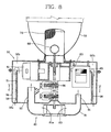
- FIG. 8 is a longitudinal sectional view showing a plasma lighting system according to the fifth preferred embodiment of the present invention
- FIG. 9 is a sectional view of the case taken along line C-C of FIG. 8 .
- air is discharged to the rear of the case 50 through the discharge duct 56 prolonged to the outer surface of the case 50 .
- radiation fins 58 protruded from the outer surface of the case 50 are provided at the inside of the discharge duct 56 .
- the radiation fins 58 can be formed toward a flow direction of the discharge air or orthogonal to the flow direction of the discharge air. Also, a shape and an arrangement of the radiation fins 58 can be different according to a design condition or a necessity.
- a portion of heat generated in the case 50 is radiated outward through the radiation fins 58 , and the air discharged through the discharge duct 56 is contacted to the radiation fins 58 , so that a contact area with air is enlarged, thereby enhancing an entire cooling efficiency of the system.
- FIG. 10 is a cross-sectional view of the case according to the sixth preferred embodiment of the present invention.
- two discharge ducts 56 are formed at the outer surface of the case 50 .
- four discharge ducts 56 are formed at the outer surface of the case 50 .
- the discharge ducts 56 are located at the circumference surface of the case 50 with predetermined intervals. Also, the number of the discharge ducts 56 can be variously constructed according the design condition even if the present invention is constructed as four discharge ducts.
- a plurality of radiation fins 59 for easily radiating heat in the case 50 are formed at the outer surface of the case 50 .
- the radiation fins 59 are preferably formed at the outer surface of the case 50 where the discharge duct 56 is not formed.
- four discharge ducts 56 are constructed, thereby reducing a discharge flow resistance of air. Also, the plurality of radiation fins 59 are formed at the outer surface of the case 50 , so that a cooling efficiency is enhanced.
- a system can effectively cool the heat generating components of high temperature such as a magnetron, thereby prolonging life span of the components and improving a performance of the system without unnecessarily enlarging a fan capacity.
Landscapes
- Physics & Mathematics (AREA)
- Electromagnetism (AREA)
- Engineering & Computer Science (AREA)
- Plasma & Fusion (AREA)
- Arrangement Of Elements, Cooling, Sealing, Or The Like Of Lighting Devices (AREA)
- Constitution Of High-Frequency Heating (AREA)
- Discharge Lamps And Accessories Thereof (AREA)
Applications Claiming Priority (1)
| Application Number | Priority Date | Filing Date | Title |
|---|---|---|---|
| PCT/KR2002/002384 WO2004055863A1 (en) | 2002-12-18 | 2002-12-18 | Cooling structure for plasma lighting system |
Publications (2)
| Publication Number | Publication Date |
|---|---|
| US20060243707A1 US20060243707A1 (en) | 2006-11-02 |
| US7973261B2 true US7973261B2 (en) | 2011-07-05 |
Family
ID=32588742
Family Applications (1)
| Application Number | Title | Priority Date | Filing Date |
|---|---|---|---|
| US10/539,552 Expired - Fee Related US7973261B2 (en) | 2002-12-18 | 2002-12-18 | Cooling structure for plasma lighting system |
Country Status (8)
| Country | Link |
|---|---|
| US (1) | US7973261B2 (ja) |
| EP (1) | EP1579476B1 (ja) |
| JP (1) | JP4335813B2 (ja) |
| CN (1) | CN100474498C (ja) |
| AT (1) | ATE389945T1 (ja) |
| AU (1) | AU2002359011A1 (ja) |
| DE (1) | DE60225736T2 (ja) |
| WO (1) | WO2004055863A1 (ja) |
Cited By (2)
| Publication number | Priority date | Publication date | Assignee | Title |
|---|---|---|---|---|
| US20150325426A1 (en) * | 2014-05-12 | 2015-11-12 | Lg Electronics Inc. | Lighting Device |
| US9924585B2 (en) | 2013-12-13 | 2018-03-20 | Asml Netherlands B.V. | Radiation source, metrology apparatus, lithographic system and device manufacturing method |
Families Citing this family (2)
| Publication number | Priority date | Publication date | Assignee | Title |
|---|---|---|---|---|
| US8410410B2 (en) * | 2006-07-12 | 2013-04-02 | Nordson Corporation | Ultraviolet lamp system with cooling air control |
| CN104392879B (zh) * | 2014-12-03 | 2016-06-22 | 成都中电锦江信息产业有限公司 | 一种大功率磁控管阴极冷却装置 |
Citations (11)
| Publication number | Priority date | Publication date | Assignee | Title |
|---|---|---|---|---|
| JPS5468082A (en) | 1977-11-11 | 1979-05-31 | Hitachi Ltd | Xenon light source |
| JPS57172648A (en) | 1981-04-15 | 1982-10-23 | Mitsubishi Electric Corp | Microwave discharge light source device |
| JPS62241257A (ja) | 1986-04-11 | 1987-10-21 | Mitsubishi Electric Corp | マイクロ波放電光源装置 |
| JPS63159211U (ja) | 1987-04-07 | 1988-10-18 | ||
| US4874036A (en) * | 1987-07-14 | 1989-10-17 | Sanden Corporation | Heating and air conditioning system for a forklift |
| US5998934A (en) * | 1997-05-15 | 1999-12-07 | Matsushita Electronics Corporation | Microwave-excited discharge lamp apparatus |
| KR20000050827A (ko) | 1999-01-15 | 2000-08-05 | 구자홍 | 마이크로파 방전광원 냉각장치 |
| JP2001155505A (ja) | 1999-11-26 | 2001-06-08 | Lg Electronics Inc | マイクロ波照明装置のプラズマランプ構造 |
| KR20020031848A (ko) | 2000-10-24 | 2002-05-03 | 구자홍 | 무전극 램프의 냉각장치 |
| CN1350698A (zh) | 1999-05-12 | 2002-05-22 | 熔化照明股份有限公司 | 高亮度微波灯 |
| KR20020054161A (ko) | 2000-12-27 | 2002-07-06 | 구자홍 | 마이크로파 조명장치의 광 반사 구조 |
-
2002
- 2002-12-18 AU AU2002359011A patent/AU2002359011A1/en not_active Abandoned
- 2002-12-18 EP EP02793485A patent/EP1579476B1/en not_active Expired - Lifetime
- 2002-12-18 DE DE60225736T patent/DE60225736T2/de not_active Expired - Lifetime
- 2002-12-18 AT AT02793485T patent/ATE389945T1/de not_active IP Right Cessation
- 2002-12-18 WO PCT/KR2002/002384 patent/WO2004055863A1/en not_active Ceased
- 2002-12-18 CN CNB028301609A patent/CN100474498C/zh not_active Expired - Fee Related
- 2002-12-18 JP JP2004560658A patent/JP4335813B2/ja not_active Expired - Fee Related
- 2002-12-18 US US10/539,552 patent/US7973261B2/en not_active Expired - Fee Related
Patent Citations (11)
| Publication number | Priority date | Publication date | Assignee | Title |
|---|---|---|---|---|
| JPS5468082A (en) | 1977-11-11 | 1979-05-31 | Hitachi Ltd | Xenon light source |
| JPS57172648A (en) | 1981-04-15 | 1982-10-23 | Mitsubishi Electric Corp | Microwave discharge light source device |
| JPS62241257A (ja) | 1986-04-11 | 1987-10-21 | Mitsubishi Electric Corp | マイクロ波放電光源装置 |
| JPS63159211U (ja) | 1987-04-07 | 1988-10-18 | ||
| US4874036A (en) * | 1987-07-14 | 1989-10-17 | Sanden Corporation | Heating and air conditioning system for a forklift |
| US5998934A (en) * | 1997-05-15 | 1999-12-07 | Matsushita Electronics Corporation | Microwave-excited discharge lamp apparatus |
| KR20000050827A (ko) | 1999-01-15 | 2000-08-05 | 구자홍 | 마이크로파 방전광원 냉각장치 |
| CN1350698A (zh) | 1999-05-12 | 2002-05-22 | 熔化照明股份有限公司 | 高亮度微波灯 |
| JP2001155505A (ja) | 1999-11-26 | 2001-06-08 | Lg Electronics Inc | マイクロ波照明装置のプラズマランプ構造 |
| KR20020031848A (ko) | 2000-10-24 | 2002-05-03 | 구자홍 | 무전극 램프의 냉각장치 |
| KR20020054161A (ko) | 2000-12-27 | 2002-07-06 | 구자홍 | 마이크로파 조명장치의 광 반사 구조 |
Cited By (4)
| Publication number | Priority date | Publication date | Assignee | Title |
|---|---|---|---|---|
| US9924585B2 (en) | 2013-12-13 | 2018-03-20 | Asml Netherlands B.V. | Radiation source, metrology apparatus, lithographic system and device manufacturing method |
| US10420197B2 (en) | 2013-12-13 | 2019-09-17 | Asml Netherlands B.V. | Radiation source, metrology apparatus, lithographic system and device manufacturing method |
| US20150325426A1 (en) * | 2014-05-12 | 2015-11-12 | Lg Electronics Inc. | Lighting Device |
| US9478406B2 (en) * | 2014-05-12 | 2016-10-25 | Lg Electronics Inc. | Lighting device with fan directed airflow and air filtering |
Also Published As
| Publication number | Publication date |
|---|---|
| EP1579476A1 (en) | 2005-09-28 |
| JP4335813B2 (ja) | 2009-09-30 |
| AU2002359011A1 (en) | 2004-07-09 |
| WO2004055863A1 (en) | 2004-07-01 |
| JP2006511043A (ja) | 2006-03-30 |
| CN1720603A (zh) | 2006-01-11 |
| ATE389945T1 (de) | 2008-04-15 |
| CN100474498C (zh) | 2009-04-01 |
| EP1579476B1 (en) | 2008-03-19 |
| DE60225736T2 (de) | 2009-04-02 |
| US20060243707A1 (en) | 2006-11-02 |
| DE60225736D1 (de) | 2008-04-30 |
Similar Documents
| Publication | Publication Date | Title |
|---|---|---|
| JP4091596B2 (ja) | 無電極ランプシステム | |
| EP1432012A2 (en) | Cooling apparatus of plasma lighting system | |
| US7521852B2 (en) | Electrodeless lighting system | |
| US7973261B2 (en) | Cooling structure for plasma lighting system | |
| KR20030028189A (ko) | 무전극 조명기기 | |
| US7081702B2 (en) | Electrodeless lighting system | |
| KR20030072776A (ko) | 마이크로 웨이브를 이용한 조명기기 | |
| US6784619B2 (en) | Electrodeless lighting system | |
| EP1703543A2 (en) | Electrodeless lighting apparatus | |
| JP3787105B2 (ja) | 無電極照明機器の外気遮断装置 | |
| KR20030072777A (ko) | 마이크로 웨이브를 이용한 조명기기 | |
| KR20050088387A (ko) | 플라즈마 라이팅 장치의 냉각 구조 | |
| KR100414090B1 (ko) | 마이크로파를 이용한 조명시스템 | |
| US7896502B2 (en) | Projection apparatus provided with a heat sink | |
| KR100400401B1 (ko) | 무전극 조명기기의 램프 방열구조 | |
| KR100421395B1 (ko) | 무전극 램프의 냉각장치 | |
| CN100466157C (zh) | 等离子体照明装置 | |
| KR100393788B1 (ko) | 마이크로파를 이용한 조명장치 및 도파관 구조 | |
| KR100539818B1 (ko) | 무전극 램프의 광전송장치 | |
| KR100498398B1 (ko) | 무전극 조명기기의 전구구조 | |
| KR100399880B1 (ko) | 무전극 조명기기의 전등장치 | |
| KR20050018140A (ko) | 무전극 조명기기의 전구구조 | |
| KR20040057680A (ko) | 플라즈마 조명장치 | |
| KR200333472Y1 (ko) | 프로젝터 | |
| KR20030008356A (ko) | 마이크로파를 이용한 조명시스템 |
Legal Events
| Date | Code | Title | Description |
|---|---|---|---|
| AS | Assignment |
Owner name: LG ELECTRONCS INC., KOREA, REPUBLIC OF Free format text: ASSIGNMENT OF ASSIGNORS INTEREST;ASSIGNORS:LEE, SUNG-HWA;SON, YOUNG-BOK;LEE, KWANG-WON;REEL/FRAME:017445/0182 Effective date: 20050613 |
|
| FEPP | Fee payment procedure |
Free format text: PAYOR NUMBER ASSIGNED (ORIGINAL EVENT CODE: ASPN); ENTITY STATUS OF PATENT OWNER: LARGE ENTITY |
|
| STCF | Information on status: patent grant |
Free format text: PATENTED CASE |
|
| FPAY | Fee payment |
Year of fee payment: 4 |
|
| FEPP | Fee payment procedure |
Free format text: MAINTENANCE FEE REMINDER MAILED (ORIGINAL EVENT CODE: REM.); ENTITY STATUS OF PATENT OWNER: LARGE ENTITY |
|
| LAPS | Lapse for failure to pay maintenance fees |
Free format text: PATENT EXPIRED FOR FAILURE TO PAY MAINTENANCE FEES (ORIGINAL EVENT CODE: EXP.); ENTITY STATUS OF PATENT OWNER: LARGE ENTITY |
|
| STCH | Information on status: patent discontinuation |
Free format text: PATENT EXPIRED DUE TO NONPAYMENT OF MAINTENANCE FEES UNDER 37 CFR 1.362 |
|
| FP | Lapsed due to failure to pay maintenance fee |
Effective date: 20190705 |