US7955484B2 - Glucose biosensor and method - Google Patents
Glucose biosensor and method Download PDFInfo
- Publication number
- US7955484B2 US7955484B2 US11/306,005 US30600505A US7955484B2 US 7955484 B2 US7955484 B2 US 7955484B2 US 30600505 A US30600505 A US 30600505A US 7955484 B2 US7955484 B2 US 7955484B2
- Authority
- US
- United States
- Prior art keywords
- glucose
- electrode
- sample
- gdh
- god
- Prior art date
- Legal status (The legal status is an assumption and is not a legal conclusion. Google has not performed a legal analysis and makes no representation as to the accuracy of the status listed.)
- Active, expires
Links
Images


Classifications
-
- C—CHEMISTRY; METALLURGY
- C12—BIOCHEMISTRY; BEER; SPIRITS; WINE; VINEGAR; MICROBIOLOGY; ENZYMOLOGY; MUTATION OR GENETIC ENGINEERING
- C12Q—MEASURING OR TESTING PROCESSES INVOLVING ENZYMES, NUCLEIC ACIDS OR MICROORGANISMS; COMPOSITIONS OR TEST PAPERS THEREFOR; PROCESSES OF PREPARING SUCH COMPOSITIONS; CONDITION-RESPONSIVE CONTROL IN MICROBIOLOGICAL OR ENZYMOLOGICAL PROCESSES
- C12Q1/00—Measuring or testing processes involving enzymes, nucleic acids or microorganisms; Compositions therefor; Processes of preparing such compositions
- C12Q1/001—Enzyme electrodes
- C12Q1/005—Enzyme electrodes involving specific analytes or enzymes
- C12Q1/006—Enzyme electrodes involving specific analytes or enzymes for glucose
-
- C—CHEMISTRY; METALLURGY
- C12—BIOCHEMISTRY; BEER; SPIRITS; WINE; VINEGAR; MICROBIOLOGY; ENZYMOLOGY; MUTATION OR GENETIC ENGINEERING
- C12Q—MEASURING OR TESTING PROCESSES INVOLVING ENZYMES, NUCLEIC ACIDS OR MICROORGANISMS; COMPOSITIONS OR TEST PAPERS THEREFOR; PROCESSES OF PREPARING SUCH COMPOSITIONS; CONDITION-RESPONSIVE CONTROL IN MICROBIOLOGICAL OR ENZYMOLOGICAL PROCESSES
- C12Q1/00—Measuring or testing processes involving enzymes, nucleic acids or microorganisms; Compositions therefor; Processes of preparing such compositions
- C12Q1/001—Enzyme electrodes
- C12Q1/004—Enzyme electrodes mediator-assisted
-
- G—PHYSICS
- G01—MEASURING; TESTING
- G01N—INVESTIGATING OR ANALYSING MATERIALS BY DETERMINING THEIR CHEMICAL OR PHYSICAL PROPERTIES
- G01N33/00—Investigating or analysing materials by specific methods not covered by groups G01N1/00 - G01N31/00
- G01N33/48—Biological material, e.g. blood, urine; Haemocytometers
- G01N33/50—Chemical analysis of biological material, e.g. blood, urine; Testing involving biospecific ligand binding methods; Immunological testing
- G01N33/66—Chemical analysis of biological material, e.g. blood, urine; Testing involving biospecific ligand binding methods; Immunological testing involving blood sugars, e.g. galactose
Definitions
- the present invention relates to a biosensor for the detection of glucose present in biological fluids such as blood.
- the present invention relates to a biosensor for the amperometric detection of glucose in biological fluids.
- the present invention relates to a biosensor having high accuracy for the amperometric detection of glucose in biological fluids.
- ADA American Diabetes Association
- Type I diabetes insulin-dependent diabetes test glucose three or more times per day. Insulin controls utilization of glucose or sugar in the blood and prevents hyperglycemia which, if left uncorrected, can lead to ketosis. Improper administration of insulin therapy, however, can result in hypoglycemic episodes. Hypoglycemia can cause coma and can be fatal.
- Hyperglycemia in diabetics has been correlated with several long-term effects of diabetes such as heart disease, atherosclerosis, blindness, stroke, hypertension and kidney failure.
- the amount of the insulin injection is related to the blood glucose level. Therefore, the accurate detection of blood glucose is vital for the proper treatment of diabetes.
- Patients with Type II (non-insulin-dependent) diabetes can also benefit from accurate blood glucose monitoring in the control of their condition by way of diet and exercise.
- glucose strips on the market are biosensors based on the use of a mediator and either glucose oxidase (GOD) or pyrroloquinoline quinone dependent glucose dehydrogenase (PQQ-GDH).
- GOD glucose oxidase
- PQQ-GDH pyrroloquinoline quinone dependent glucose dehydrogenase
- the mediator/GOD-based biosensors extend the linear response range for glucose, as compared to the non-mediator based biosensors (hydrogen peroxide measurement is involved). Oxygen-related drawbacks, however, still exist. Mediators are not as efficient at shuttling electrons with the enzyme as is the oxygen molecule. In fact, any oxygen in the sample solution can compete more effectively than the mediators for the enzyme site. The measurements with the mediator/GOD-based biosensors show significantly lower results with increasing oxygen partial pressure (pO 2 ) in the fluid samples. The inaccurate testing results caused by varying oxygen concentration were extensively investigated by several groups (T. Y. Chun, M. Hirose, T. Sawa, M. Harada, T. Hosokawa, Y. Tanaka and M.
- the typical oxygen partial pressure of a venous blood sample is about 32 ⁇ 7 mmHg. In some cases, it can be as low as 20 mmHg. For an arterial sample, one can expect much higher oxygen levels. For the patients who are in o oxygen therapy, the level of arterial pO 2 can reach as high as 700 mmHg. Thus, the mediator/GOD-based biosensors could give inaccurate testing results due to the different oxygen concentrations. This becomes more serious when the glucose concentration is at a low level (e.g. glucose concentration less than 70 mg/dL).
- glucose dehydrogenase GDH was recently used to replace the oxygen-sensitive glucose oxidase.
- Glucose dehydrogenase whose coenzyme is pyrroloquinoline quinone (PQQ), does not interact with oxygen. Therefore, the resultant glucose sensor is unaffected by variable oxygen concentration in the sample.
- glucose dehydrogenase does overcome the problems caused by the oxygen effect.
- glucose dehydrogenase is not as specific as glucose oxidase. It not only reacts with glucose but also reacts with other sugars like galactose and maltose. Both galactose and maltose have a similar structure to glucose.
- Maltose is composed of two glucose units and galactose differs in structure from glucose only in the position of the hydroxyl group on carbon no. 4. Severe interference can be expected.
- the GDH-based biosensors are more sensitive to maltose and have no discrimination between glucose and galactose (J. D. Newman, C. A. Ramsden, N. D. H. Balazs, Clinical Chemistry, 48, 2071, 2002).
- a falsely high glucose reading may be obtained by patients if test strips use a glucose dehydrogenase pyrroloquinoline quinone as the enzyme method. For this reason, the Centers for Medicare & Medicaid Services and ESRD Networks were alerted by the Food and Drug Administration (FDA) on Apr. 18, 2003, to a concern with peritoneal dialysis patients' glucose readings while on Icodextrin Extraneal dialysis solution and the effects of falsely elevated glucose readings because of the interaction of maltose.
- FDA Food and Drug Administration
- a false high blood glucose reading could cause a patient to be given more insulin than needed. This, in turn, can lower a patient's blood sugar unnecessarily and can cause a serious reaction including loss of consciousness.
- a glucose measuring system that can provide a more accurate blood glucose reading.
- a glucose measuring system that can provide a more accurate blood glucose reading by reducing inaccurate test results caused by varying oxygen partial pressure in the fluid sample.
- a glucose measuring system that can provide a more accurate blood glucose reading by reducing inaccurate test results caused by other sugars in the fluid sample.
- a disposable glucose sensor capable of providing more accurate blood glucose readings.
- the present invention achieves these and other objectives by incorporating two glucose electrodes, each incorporating a different enzyme for measuring glucose, and selecting the appropriate electrode response to determine the glucose concentration in a fluid sample.
- the two enzymes are glucose oxidase (GOD) and a quinoprotein glucose dehydrogenase (GDH), more specifically known as pyrroloquinoline quinone dependent glucose dehydrogenase (PQQ-GDH).
- GOD glucose oxidase
- GDH quinoprotein glucose dehydrogenase
- PQQ-GDH pyrroloquinoline quinone dependent glucose dehydrogenase
- Both glucose (i.e. working) electrodes respond to the glucose concentration over the entire linear range. If the sample has a lower level of pO 2 , the GOD-based working electrode will give higher response while the GDH-based working electrode gives an accurate result. Thus, the preferred response should be from the GDH-based working electrode.
- the GDH-based working electrode will show higher response while the GOD-loaded working electrode gives an accurate result.
- the preferred response should be from the GOD-loaded working electrode.
- the selection process is preferably done automatically when the glucose electrode readings are automatically fed into a preprogrammed meter.
- the glucose sensor of the present invention incorporates several embodiments including, but not limited to, a 4-layer construction and a 3-layer construction as disclosed in U.S. Pat. Nos. 6,767,441, 6,287,451, 6,258,229, 6,837,976, and 6,942,770, all of which are incorporated herein by reference.
- the glucose sensor uses a 4-layer laminated construction.
- the glucose sensor has a laminated, elongated body having a sample fluid channel, which forms a substantially flat sample chamber, connected between an opening on one end of the laminated body and a vent hole spaced from the opening.
- a sample fluid channel which forms a substantially flat sample chamber
- Within the fluid channel lie at least two working electrodes and a reference/counter electrode.
- the arrangement of the two or more working electrodes and the reference electrode is not important for purposes of the results obtained from the sensor.
- the working electrodes and the reference electrode are each in electrical contact with separate conductive paths. The separate conductive paths terminate and are exposed for making an electrical connection to a reading device on the end opposite the sample entrance end of the laminated body.
- the laminated body has a base layer made from a plastic material.
- Several conductive paths are delineated on the base layer.
- the conductive paths may be deposited on the insulating layer by screen printing, by vapor deposition, or by any method that provides for a conductive layer that adheres to the base layer.
- the conductive paths may be individually disposed on the insulating layer, or a conductive layer may be disposed on the insulating layer followed by etching/scribing the required number of conductive paths.
- the etching process may be accomplished chemically, by mechanically scribing lines in the conductive layer, by using a laser to scribe the conductive layer into separate conductive paths, or by any means that will cause a break between and among the separate conductive paths required by the present invention.
- Conductive coatings or layers that may be used are coatings of copper, gold, tin oxide/gold, palladium, other noble metals or their oxides, or carbon film compositions.
- the preferred conductive coatings are gold film or a tin oxide/gold film composition.
- the laminated body has a first middle insulating layer, also called a reagent holding or electrode area defining layer, on top of the base layer and the conductive paths.
- the reagent holding layer, or reagent holding layer contains at least two openings for two or more working electrodes and a reference electrode. Each opening corresponds to and exposes a small portion of a single conductive path.
- the openings for the working electrodes are substantially the same size.
- the opening for the reference electrode may be the same or different size as the openings for the working electrodes. The placement of all of the openings is such that they will all be all positioned within the sample fluid channel described above.
- the reagent holding layer is also made of an insulating dielectric material, preferably plastic, and may be made by die cutting the material mechanically or with a laser and then fastening the material to the base layer.
- An adhesive such as a pressure-sensitive adhesive, may be used to secure the first middle insulating layer to the base layer. Adhesion may also be accomplished by ultrasonically bonding the reagent holding layer to the base layer.
- the reagent holding layer may also be made by screen printing an insulating material or by binding a photopolymer over the base layer.
- the laminated body also has a second middle insulating layer, also called a channel-forming layer, on top of the reagent holding layer.
- the channel forming layer is also made of a plastic insulating material and creates the sample chamber of the laminated body. It contains a U-shaped opening on one end which overlays the openings on the reagent holding layer with the open end corresponding to the sample entrance end of the laminated body described earlier.
- a double coated, pressure-sensitive adhesive tape may be used as the channel forming layer.
- the laminated body of the present invention has a cover with a vent opening and an entrance notch.
- the vent opening is located such that at least a portion of the vent opening overlays the base of the U-shaped cutout of the channel forming layer.
- the vent allows air within the sample fluid channel to escape as the sample fluid enters the sample entrance or sample inlet of the laminated body.
- the notch is located at the sample entrance end.
- the sample fluid generally fills the sample chamber by capillary action. In small volume situations, the extent of capillary action is dependent on the hydrophobic/hydrophilic nature of the surfaces in contact with the fluid undergoing capillary action.
- Capillary forces are enhanced by either using a hydrophilic insulating material to form the cover, or by coating at least a portion of one side of a hydrophobic insulating material with a hydrophilic substance in the area of the cover that faces the sample chamber between the open end of the laminated body and the vent opening of the cover. It should be understood that an entire side of the cover may be coated with the hydrophilic substance and then bonded to the channel forming layer.
- one opening contains electrode material for the first working electrode (W 1 ) loaded with GOD, a mediator and other indigents, one for the second working electrode (W 2 ) loaded with pyrroloquinoline quinone dependent glucose dehydrogenase (PQQ-GDH), a mediator and other indigents, and one for the reference electrode (R).
- the positional arrangement of the working electrodes and the reference electrode in the channel is not critical for obtaining usable results from the electrochemical sensor.
- the possible electrode arrangements within the sample fluid channel may be W 1 -W 2 -R, W 1 -R-W 2 , R-W 1 -W 2 , W 2 -W 1 -R, W 2 -R-W 1 , or R-W 2 -W 1 , with the arrangement listed as the electrodes would appear from the sample entrance of the laminated body to the vent opening.
- the preferred position was found to be W 1 -W 2 -R; that is, as the sample fluid entered the open end of the laminated body, the fluid would cover W 1 first, then W 2 , then R.
- the preferred position obviates reliability and accuracy problems due to an insufficient sample fluid size.
- the working electrodes and the reference electrode are each in electric contact with separate conductive paths, respectively. The separate conductive paths terminate and are exposed for making an electrical connection to a reading device on the end opposite of the sample entrance end of the laminated body.
- the working electrodes are loaded with a mixture of at least a redox mediator and an enzyme (GOD or PQQ-GDH), and optionally with one or more of a surfactant, a polymer binder, and a buffer.
- the reference electrode may be loaded with the same mixture as the working electrode. It should be pointed out that the reference electrode opening could be loaded with a redox mediator (either reduced or oxidized form or the mixture) with or without at least a surfactant, a polymer binder and a buffer. Alternatively, the reference electrode opening could also be loaded with a Ag/AgCl layer (e.g. by applying Ag/AgCl ink or by sputter-coating a silver or silver/silver chloride layer) or other reference electrode materials.
- the glucose sensor has a similar structure to the first embodiment, but it has an additional blank electrode, which is loaded with a mediator and other ingredients without adding glucose sensitive enzyme.
- Such a four-electrode system not only possesses the feature of the first embodiment, but also the capability of eliminating interference from oxidizable species in the sample such as ascorbic acid, acetaminophen and uric acid etc.
- At least four conductive paths are delineated on the base layer.
- the reagent holding layer contains at least four openings for three working electrodes and a reference electrode.
- one opening contains electrode material for the first working electrode (W 1 ) loaded with GOD, a mediator and other indigents, one for the second working electrode (W 2 ) loaded with PQQ-GDH, a mediator and other indigents, one for the blank electrode (B) loaded with a mediator and other indigents, and one for the reference electrode (R).
- the positional arrangement of the working electrodes, blank electrode and the reference electrode in the channel is not critical for obtaining usable results from the electrochemical sensor.
- the preferred position was found to be W 1 -W 2 -R-B; that is, as the sample fluid entered the open end of the laminated body, the fluid would cover W 1 first, then W 2 , then R, then B.
- the glucose sensor has a similar structure to the first embodiment, but without using the reagent holding layer.
- the three remaining layers are the same as in the first embodiment.
- the details of this construction have been disclosed in U.S. Pat. No. 6,258,229.
- the U-shaped channel cutout is located at the sensor end (sample entrance end).
- the length, thickness and width of the U-shaped channel cutout define the capillary channel size or volume.
- the length and width of the U-shaped channel cutout along with the base conductive layer define the areas of the working and reference electrodes and the sample chamber, but, as disclosed above, may have an alternative chemical construction.
- the working electrodes (W 1 and W 2 ) are loaded with at least an enzyme (GOD or PQQ-GDH), a redox mediator, a polymer binder, a surfactant and a buffer.
- the reference electrode (R) is preferably covered by the same reagent mixture as one of the working electrodes.
- the glucose sensor is based on screen-printing technology.
- the conductive ink e.g. carbon ink for working electrodes; silver/silver chloride ink for reference electrode
- the capillary channel can be formed by applying a U-shape spacer and a cover as described in the previous embodiments.
- the U-shaped channel cutout is located at the sensor end (sample entrance end). The length, thickness and width of the U-shaped channel cutout define the capillary channel size or volume.
- the working electrodes (W 1 and W 2 ) are loaded with at least an enzyme (GOD or GDH-PQQ), a redox mediator, a polymer binder, a surfactant and a buffer.
- the reference electrode (R) may or may not be covered by the same reagent mixture as one of the working electrodes.
- the enzymes and redox mediator and other ingredients can be mixed with the ink and screen-printed onto the base insulated layer.
- the glucose sensor has two channels (channel 1 and channel 2 ) on the same strip; each channel can have a similar structure to those mentioned in the above embodiments.
- Channel 1 and channel 2 are arranged side by side or back to back.
- the sample entrances of the two channels are close to each other; or the two channels simply share the same sample entrance.
- Channel 1 has at least one working electrode and one reference electrode. At least one of the working electrodes is loaded with GOD, a mediator and other ingredients. Channel 1 can function independently as one glucose sensor.
- Channel 2 has at least one working electrode and one reference electrode. At least one of the working electrodes is loaded with PQQ-GDH, a mediator and other ingredients. Channel 2 can function independently as another glucose sensor independently.
- the disposable strip has a sensor body with an open well forming a test chamber, at least two working electrodes and a reference electrode within the test chamber, and electrical contacts for electrically connecting the at least two working electrodes and the reference electrode to a meter device.
- the test chamber contains at least two reagents, one on each of the at least two working electrodes where one of the reagents contains GOD and the other contains GDH.
- the meter device must be capable of providing a biasing potential across the working electrodes and the reference electrode and detecting a current generated by the presence of glucose in a fluid sample disposed into the open well of the disposable strip.
- FIG. 1 is a perspective view of one embodiment of the present invention showing the test strip.
- FIG. 2 is an exploded view of the embodiment in FIG. 1 showing the four component layers of the test strip.
- FIG. 3 is a perspective view of another embodiment of the present invention showing the test strip.
- FIG. 4 is an exploded view of the embodiment in FIG. 3 showing the three component layers of the test strip.
- FIG. 5 is a perspective view of another embodiment of the present invention showing the combination of a four-layer GOD-based sensor strip and a four-layer GDH-based sensor strip.
- FIG. 6 is an exploded view of the embodiment in FIG. 5 showing the arrangement of the component layers of the GOD-based sensor strip and the GDH-based sensor strip.
- FIG. 7 is a perspective view of another embodiment of the present invention showing the combination of a three-layer GOD-based sensor strip and a three-layer GDH-based sensor strip.
- FIG. 8 is an exploded view of the embodiment in FIG. 7 showing the arrangement of the component layers of the GOD-based sensor strip and the GDH-based sensor strip.
- FIG. 9 is a perspective view of another embodiment of the present invention showing the combination of a four-layer GOD-based sensor strip and a four-layer GDH-based sensor strip where the base layer is common to both sensors.
- FIG. 10 is an exploded view of the embodiment in FIG. 9 showing the arrangement of the component layers of the GOD-based sensor and the GDH-based sensor.
- FIG. 11 is a perspective view of another embodiment of the present invention showing the combination of a three-layer GOD-based sensor strip and a three-layer GDH-based sensor strip where the base layer is common to both sensors.
- FIG. 12 is an exploded view of the embodiment in FIG. 111 showing the arrangement of the component layers of the GOD-based sensor and the GDH-based sensor.
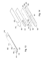
- FIG. 13 is a perspective view of another embodiment of the present invention showing a combined sensor strip having the four-layer construction with two working electrodes and a blank electrode, namely, a GOD-based electrode, a GDH-based electrode and an interferant-compensating electrode.
- FIG. 14 is an exploded view of the embodiment in FIG. 13 showing the arrangement of the component layers that includes a GOD-based electrode, a GDH-based electrode, an interferent-compensating electrode, and a reference electrode.
- FIG. 15 is a perspective view of another embodiment of the present invention showing a combined sensor strip having the four-layer construction with a GOD-based sensor system side-by-side with a GDH-based electrode.
- FIG. 16 is an exploded view of the embodiment in FIG. 15 showing the arrangement of the component layers that includes the GOD-based electrode system and the GDH-based electrode system.
- FIG. 17 is a perspective view of another embodiment of the present invention showing a combined sensor strip having the three-layer construction with a GOD-based sensor system side-by-side with a GDH-based electrode.
- FIG. 18 is an exploded view of the embodiment in FIG. 17 showing the arrangement of the component layers that includes the GOD-based electrode system and the GDH-based electrode system.
- FIG. 19 illustrates a perspective view of another embodiment of the present invention.
- FIGS. 20 and 21 illustrate the correlation between the current response of the GOD-based electrode at different oxygen levels.
- FIGS. 22 and 23 illustrate the correlation between the current response of the GDH-based electrode at different oxygen levels.
- FIG. 24 illustrates the correlation of glucose concentration determined by the GOD-based electrode to that of a reference analyzer in a sample containing an oxygen level of 90 mm Hg.
- FIG. 25 illustrates the correlation of glucose concentration determined by the GDH-based electrode to that of a reference analyzer in a sample containing an oxygen level of 90 mm Hg.
- the preferred embodiments of the present invention are illustrated in FIGS. 1-25 .
- the glucose sensor of the present invention can be made using either a 4-layer construction ( FIG. 1 ) or a 3-layer construction ( FIG. 3 ).
- the 4-layer construction has the same three layers as the 3-layer construction and an additional reagent holding layer between a base/bottom layer and a channel forming layer.
- the glucose strip 10 has a laminated body 12 , a fluid sampling end 14 , an electrical contact end 16 , and a vent opening 52 .
- Fluid sampling end 14 includes a sample chamber 17 between a sample inlet 18 and vent opening 52 .
- Electrical contact end 16 has three discrete conductive contacts 16 a , 16 b and 16 c.
- laminated body 12 is composed of a base layer 20 , a reagent holding layer 30 , a channel forming layer 40 , and a cover 50 . All layers of laminated body 12 are made of a dielectric material, preferably plastic. Examples of a preferred dielectric material are polyvinyl chloride, polycarbonate, polysulfone, nylon, polyurethane, cellulose nitrate, cellulose propionate, cellulose acetate, cellulose acetate butyrate, polyester, polyimide, polypropylene, polyethylene and polystyrene.
- Base layer 20 has a conductive layer 21 on which is delineated three conductive paths 22 , 24 and 26 .
- the conductive paths 22 , 24 , 26 may be formed by scribing or scoring conductive layer 21 , or by silk-screening conductive paths 22 , 24 , 26 onto base layer 20 . Scribing or scoring of conductive layer 21 may be done by mechanically scribing the conductive layer 21 sufficiently to create the three independent conductive paths 22 , 24 , 26 .
- the preferred scribing or scoring method of the present invention is done by using a carbon dioxide laser, a YAG laser or an eximer laser.
- Conductive layer 21 may be made of any electrically conductive material such as, for example, gold, tin oxide/gold, palladium, other noble metals or their oxides, or carbon film compositions.
- the preferred electrically conductive material is gold or tin oxide/gold.
- a usable material for base layer 20 is a tin oxide/gold polyester film (Cat. No. FM-1) or a gold polyester film (Cat. No. FM-2) sold by Courtaulds Performance Films, Canoga Park, Calif.
- reagent holding layer 30 has three reagent holding openings 32 , 34 and 36 .
- Reagent holding opening 32 exposes a portion of conductive path 22
- reagent holding opening 34 exposes a portion of conductive path 24
- reagent holding opening 36 exposes a portion of conductive path 26 creating reagent holding wells.
- Reagent holding layer 30 is made of a plastic material, preferably a medical grade one-sided adhesive tape available from Adhesive Research, Inc., of Glen Rock, Pa. Acceptable thicknesses of the tape for use in the present invention are in the range of about 0.001 in. (0.025 mm) to about 0.005 in. (0.13 mm).
- Reagent holding layer 30 may be made from a plastic sheet and may be coated with a pressure sensitive adhesive, a photopolymer, ultrasonically-bonded to base layer 20 , or silk-screened onto the base layer 20 to achieve the same results as using the polyester tape mentioned.
- the three reagent holding openings 32 , 34 , 36 define electrode areas W 1 , W 2 and R, respectively, and hold chemical reagents forming two working electrodes (a GOD-based glucose electrode and a GDH-based glucose electrode) and one reference electrode. Generally, the electrode areas are loaded with the reagent mixtures.
- the reagent mixtures for the working electrode areas 32 , 34 , 36 are a mixture of enzymes and redox mediators with optional polymers, surfactants, and buffers.
- a reference reagent matrix may be loaded in electrode area R that is similar to the reagent mixture of the working electrodes.
- electrode area R must be loaded with a redox reagent or mediator to make the reference electrode function when using the preferred conductive coating material.
- the reference reagent mixture preferably contains either oxidized or a mixture of an oxidized and reduced form of redox mediators, at least one binder, a surfactant and an antioxidant (if a reduced form of redox mediator is used) and a bulking agent.
- the reference electrode electroactive electrode
- the reference electrode could be also loaded with a Ag/AgCl layer (e.g. by applying Ag/AgCl ink or by sputter-coating a Ag or Ag/AgCl layer) or other reference electrode materials that do not require a redox mediator to function properly.
- the size of the reagent holding openings is preferred to be made as small as possible in order to make the sample chamber of the glucose sensor as short as possible while still being capable of holding sufficient chemical reagent to function properly.
- the preferred shape of the reagent holding openings is round and has a preferred diameter of about 0.03 in. (0.76 mm).
- the three reagent holding openings 32 , 34 , 36 are aligned with each other and are spaced about 0.025 in. (0.625 mm) from each other.
- the circular reagent holding openings are for illustrative purposes only and it should be understood that the shape of the reagent holding openings is not critical.
- the positional arrangement of the working electrode and the reference electrode in the channel is not critical for obtaining usable results from the glucose sensor.
- the possible electrode arrangements within the sample fluid channel may be W 1 -W 2 -R, W 1 -R-W 2 , R-W 1 -W 2 , W 2 -W 1 -R, W 2 -R-W 1 , or R-W 2 -W 1 , with the arrangement listed as the electrodes would appear from the sample inlet 18 of laminated body 12 to the vent opening 52 .
- the preferred position was found to be W 1 -W 2 -R; that is, as the fluid sample enters sampling end 14 of laminated body 12 , the fluid sample would cover W 1 first, then W 2 , then R.
- Such an arrangement may be beneficial for obtaining usable results when the sample is insufficient or partially insufficient.
- the working electrodes and the reference electrode are each in electrical contact with separate conductive paths.
- the separate conductive paths terminate and are exposed for making an electrical connection to a reading device on the end opposite the sample inlet 18 of laminated body 12 .
- channel forming layer 40 has a U-shaped cutout 42 located at the fluid sampling end 14 .
- the length of cutout 42 is such that when channel forming layer 40 is laminated to reagent holding layer 30 , electrode areas W and R are within the space defined by cutout 42 .
- the length, width and thickness of the U-shaped cutout 42 define the capillary channel volume.
- the thickness of channel forming layer 40 can affect the speed of the sample fluid flow into the fluid sample channel, which is filled by capillary action of the sample fluid.
- Channel forming layer 40 is made of a plastic material, preferably a medical grade double-sided pressure sensitive adhesive tape available from Adhesive Research, Inc., of Glen Rock, Pa.
- Acceptable thicknesses of the tape for use in the present invention are in the range of about 0.001 in. (0.025 mm) to about 0.010 in. (0.25 mm).
- One such tape is Arcare® 7840 (about 0.0035 in. (0.089 mm)).
- U-shaped cutout 42 can be made with a laser or by die-cutting. The preferred method is to die-cut the cutout. The preferred size of the U-shaped cutout is about 0.05 in. wide (1.27 mm) and about 0.0035 in. thick (0.089 mm). The length is dependent on the number of the layer 2 openings.
- Cover 50 which is laminated to channel forming layer 40 , has vent opening 52 spaced from the fluid sampling end 14 of glucose sensor 10 to insure that fluid sample in the sample chamber 17 will completely cover electrode areas W 1 , W 2 and R.
- Vent opening 52 is positioned in cover 50 so that it will align somewhat with U-shaped cutout 42 .
- vent opening 52 will expose a portion of and partially overlay the base of the U-shaped cutout 42 .
- the preferable shape of vent hole 52 is a rectangle with dimensions of about 0.08 in. (2 mm) by about 0.035 in. (0.9 mm).
- the top layer also has a notch 54 at fluid sampling end 14 to facilitate loading of the fluid sample into sample chamber 17 .
- the preferred shape is a half circle, which is located approximately in the middle of the channel entrance.
- the preferred size is 0.028 in. (0.71 mm) in diameter.
- the preferred material for cover 50 is a polyester film. In order to facilitate the capillary action, it is desirable for the polyester film to have a highly hydrophilic surface that faces the capillary channel.
- Transparency films (Cat. No. PP2200 or PP2500) from 3M are the preferred material used as the cover in the present invention.
- FIG. 3 illustrates a 3-layer glucose sensor 10 ′.
- glucose sensor 10 ′ has a laminated body 12 , a fluid sampling end 14 , an electrical contact end 16 , and a vent opening 52 .
- Fluid sampling end 14 includes a sample chamber 17 between a sample inlet 18 and vent opening 52 .
- Electrical contact end 16 has three discrete conductive contacts 16 a , 16 b and 16 c.
- laminated body 12 is composed of a base layer 20 , a channel forming layer 40 , and a cover 50 .
- all layers of laminated body 12 are made of a dielectric material, preferably plastic.
- Channel forming layer 40 also delineates the area in which a pre-determined amount of reagent mixtures are disposed onto the conductive paths as three distinct drops or droplets on the two working electrodes and the reference electrode, respectively.
- FIG. 5 shows a combination of a GOD-based glucose sensor 10 and a GDH-based glucose sensor 300 .
- Both GOD-based glucose sensor 10 and GDH-based glucose sensor 300 are made of the 4-layer construction where the base layers of each sensor are laminated to each other forming an integrated glucose sensor combination.
- Each sensor has a laminated body 12 , 312 , a fluid sampling end 14 , 314 , an electrical contact end 16 , 316 , and a vent opening 52 , 352 (not shown).
- Fluid sampling ends 14 , 314 include sample chambers (not shown) between sample inlets 18 , 318 and vent openings 52 , 352 , respectively.
- each sensor 10 , 300 has a base layer 20 , 320 , a reagent holding layer 30 , 330 , a channel forming layer 40 , 340 , and a cover 50 , 350 .
- Reagent holding layers 30 , 330 have reagent holding openings 32 , 34 and 332 , 334 , respectively.
- Channel forming layers 40 , 340 have U-shaped cutouts 42 , 342 , respectively.
- an adhesive is used to hold sensors 10 and 300 together.
- an additional layer (not shown) with adhesive on both sides is used to facilitate assembly of sensor 10 to sensor 300 .
- FIG. 7 shows another combination embodiment of a GOD-based glucose sensor 10 ′ and a GDH-based glucose sensor 300 ′.
- Both GOD-based glucose sensor 10 ′ and GDH glucose sensor 300 ′ are made of the 3-layer construction where the bases of each sensor are laminated to each other forming an integrated combination.
- Each sensor has a laminated body 12 , 312 , a fluid sampling end 14 , 314 , an electrical contact end 16 , 316 , and a vent opening 52 , 352 (not shown).
- Fluid sampling ends 14 , 314 include sample chambers (not shown) between sample inlets 18 , 318 and vent openings 52 , 352 , respectively.
- each sensor 10 ′, 300 ′ has a base layer 20 , 320 , a channel forming layer 40 , 340 , and a cover 50 , 350 .
- Channel forming layers 40 , 340 have U-shaped cutouts 42 , 342 , respectively.
- FIG. 9 illustrates a GOD-based glucose sensor and a GDH-based glucose sensor combination 200 with a 7-layer laminated body 212 .
- the combination includes a GOD-based glucose sensor 210 and a GDH-based glucose sensor 210 ′.
- Laminated body 212 includes a fluid sampling end 214 , an electrical contact end 216 and vent openings 252 , 252 ′ (not shown).
- Fluid sampling end 14 includes two sample fluid channels (not shown); one between sample inlet 218 and vent opening 252 and the other between sample inlet 218 ′ and vent opening 252 ′ (not shown).
- FIG. 10 shows an expanded view of laminated body 212 of the embodiment in FIG. 9 .
- Laminated body 212 has a central, base layer 220 with a conductive coating 221 , 221 ′ on each side delineating the conductive paths for the working and reference electrodes of each sensor.
- Each side of central, base layer 220 includes a reagent holding layer 230 , 230 ′, a channel forming layer 240 , 240 ′, and a cover 250 , 250 ′.
- Reagent holding layers 230 , 230 ′ have reagent holding openings 232 , 234 and 232 ′, 234 ′, respectively.
- Channel forming layers 240 , 240 ′ have U-shaped cutouts 242 , 242 ′, respectively.
- FIG. 11 illustrates a GOD-based glucose sensor and a GDH-based glucose sensor combination 400 with a 5-layer laminated body 412 .
- the combination 400 includes a GOD-based glucose sensor 410 and a GDH-based glucose sensor 410 ′.
- Laminated body 412 includes a fluid sampling end 414 , an electrical contact end 416 and vent openings 452 , 452 ′ (not shown).
- Fluid sampling end 414 includes two sample chambers (not shown); one between sample inlet 418 and vent opening 452 and the other between sample inlet 418 ′ and vent opening 452 ′ (not shown).
- FIG. 12 shows an expanded view of laminated body 412 of the embodiment in FIG. 11 .
- Laminated body 412 has a central, base layer 420 with a conductive coating 421 , 421 ′ on each side delineating the conductive paths for the working and reference electrodes of each sensor.
- Each side of central, base layer 420 includes a channel forming layer 440 , 440 ′ and a cover 450 , 450 ′.
- Channel forming layers 440 , 440 ′ have U-shaped cutouts 442 , 442 ′, respectively.
- the inlet notch may be incorporated into the base layers and the reagent holding layers to facilitate loading of a portion of the fluid sample in each of the sample chambers of the GOD-based and the GDH-based glucose sensors.
- FIG. 13 illustrates yet another embodiment of the present invention showing a combination GOD-based and a GDH-based glucose sensor with intereferant correction.
- FIG. 13 shows a combination GOD-based and a GDH-based glucose sensor 600 with a laminated body 612 , a fluid sampling end 614 , an electrical contact end 616 and a vent opening 652 .
- Sensor 600 may also include an optional inlet notch 654 .
- Fluid sampling end 614 includes a fluid sample chamber 617 between sample inlet 618 and vent opening 652 .
- FIG. 14 shows an expanded view of laminated body 612 of the embodiment in FIG. 13 .
- Laminated body 612 has a base layer 620 , a reagent holding layer 630 , a channel forming layer 640 with a U-shaped cutout 642 , and a cover 650 with an optional inlet notch 654 .
- Base layer 620 has a conductive layer 621 on which is delineated at least four conductive paths 622 , 624 , 626 , and 628 .
- Reagent holding layer 630 has at least four reagent holding openings 632 , 634 , 636 , and 638 .
- Reagent holding opening 632 exposes a portion of conductive path 622
- reagent holding opening 634 exposes a portion of conductive path 624
- reagent holding opening 636 exposes a portion of conductive path 626
- reagent holding opening 638 exposes a portion of conductive path 628 ; all forming respective electrode wells.
- the four reagent holding openings 632 , 634 , 636 , and 638 define electrode areas W 1 , W 2 , R, and B, respectively, and hold chemical reagents forming a first working electrode, a second working electrode, one reference electrode, and a blank electrode.
- electrode area W 1 is loaded with a GOD-based reagent that includes a glucose oxidase and a redox mediator (preferably an oxidized form of the redox mediator).
- Electrode area W 2 is loaded with a GDH-based reagent that includes PQQ-GDH and a redox mediator (preferably an oxidized form of the redox mediator).
- a reference reagent matrix may be loaded in both electrode area B and electrode area R that is similar to the GOD-based reagent mixture or the GDH-based reagent mixture without the glucose-based enzymes.
- electrode area R must be loaded with a reference reagent such as, for example, a redox couple/a redox reagent.
- Electrode area R may, in the alternative, be loaded with a Ag/AgCl layer (e.g. by applying Ag/AgCl ink or by sputter-coating a Ag or Ag/AgCl layer) or other reference electrode materials.
- Electrode area B may be loaded with any reagent mixture without an addition of glucose-based enzyme.
- oxidizable interferants such as ascorbic acid, uric acid and acetaminophen, to name a few, (which also cause inaccurate readings in the output of the electrochemical biosensor), can also be measured to compensate the sensor readings for these interferants.
- the interferant effect can be negated by subtracting the current response at B (blank electrode) from the current response from W 2 (second working electrode) as well as W 1 (first working electrode) to calculate the concentration in the sample fluid. This is achieved by maintaining the surface area ratio of B to W 2 and B to W 1 constant.
- FIG. 15 there is illustrated a 4-layer configuration of another embodiment of the present invention showing a combination of a GOD-based sensor system and a GDH-based sensor system in a side-by-side configuration.
- FIG. 15 shows a combination GOD-based and a GDH-based glucose sensor 700 with a laminated body 712 , a fluid sampling end 714 , an electrical contact end 716 and a vent opening 752 .
- Sensor 700 may also include an optional inlet notch 754 .
- Fluid sampling end 714 includes a first sample chamber 717 a and a second sample chamber 717 b between sample inlet 718 and vent opening 752 .
- sample inlet 718 may optionally be two inlets (one for each of the fluid sample channels) adjacent each other and that vent opening 752 may also optionally incorporate separate vent openings for each of the fluid sample channels.
- one of the sample chambers incorporates the GOD-based sensor system and the other sample chamber incorporates the GDH-based sensor system.
- FIG. 16 shows an expanded view of laminated body 712 of the embodiment in FIG. 15 .
- Laminated body 712 has a base layer 720 , a reagent holding layer 730 , a channel forming layer 740 with a fork-shaped cutout 742 having a first leg 742 a and a second leg 742 b that form sample chambers 717 a , 717 b , respectively, and a cover 750 with an optional inlet notch 754 .
- Base layer 720 has a conductive layer 721 on which is delineated at least four conductive paths 722 , 724 , 728 , and 729 .
- Conductive layer 721 may also include additional conductive paths 726 , 727 to provide interferant and/or hematocrit compensating electrodes.
- Reagent holding layer 730 has at least four reagent holding openings 732 , 734 , 738 , and 739 .
- Reagent holding opening 732 exposes a portion of conductive path 722
- reagent holding opening 734 exposes a portion of conductive path 724
- reagent holding opening 738 exposes a portion of conductive path 728
- reagent holding opening 739 exposes a portion of conductive path 729 ; all forming respective electrode reagent wells.
- reagent holding layer 730 would include additional reagent holding openings that would expose portions of other conductive paths such as, for example, conductive paths 726 and 727 .
- FIG. 17 illustrates a 3-layer configuration of another embodiment of the present invention showing a combination of a GOD-based sensor system and a GDH-based sensor system in a side-by-side configuration.
- FIG. 17 shows a combination GOD-based and a GDH-based glucose sensor 800 with a laminated body 812 , a fluid sampling end 814 , an electrical contact end 816 and a vent opening 852 .
- Sensor 800 may also include an optional inlet notch 854 .
- Fluid sampling end 814 includes a first sample chamber 817 a and a second sample chamber 817 b between sample inlet 818 and vent opening 852 .
- sample inlet 818 may optionally be two inlets (one for each of the sample chambers) adjacent each other and that vent opening 852 may also optionally incorporate separate vent openings for each of the sample chambers.
- one of the sample chambers incorporates the GOD-based sensor system and the other sample chamber incorporates the GDH-based sensor system.
- FIG. 18 shows an expanded view of laminated body 812 of the embodiment in FIG. 17 .
- Laminated body 812 has a base layer 820 , a channel forming layer 840 with a fork-shaped cutout 842 having a first leg 842 a and a second leg 842 b that form fluid sample channels 817 a , 817 b , respectively, and a cover 850 with an optional inlet notch 854 .
- Base layer 820 has a conductive layer 821 on which is delineated at least four conductive paths 822 , 824 , 828 , and 829 .
- Conductive layer 821 may also include additional conductive paths 826 , 827 to provide additional electrode systems.
- Disposable sensor 900 has a laminated body 912 , a sample receiving well 914 and an electrical contact end 916 .
- Laminated body 912 has a base layer 920 and a cover 950 .
- Cover 950 has a sample opening 952 that forms, when combined with base layer 920 , sample receiving well 914 .
- Base layer 920 has at least three electrical paths 922 , 924 and 926 , which have a first portion exposed at electrical contact end 916 for connection to a meter device (not shown) and a second portion exposed by sample receiving well 914 .
- the second portion of electrical paths 922 , 924 and 926 exposed by sample receiving well 914 create at least a first working electrode W 1 , a second working electrode W 2 and at least a reference/counter electrode R 1 .
- a partition is preferred in order to separate W 1 and W 2 .
- a first reagent mixture 960 contains at least glucose oxidase and is disposed on the first working electrode W 1 .
- a second reagent mixture 962 contains at least glucose dehydrogenase and is disposed on the second working electrode W 2 .
- the reference/counter electrode R 1 may contain any reference material previously disclosed.
- sample receiving well 914 serves as both the sample inlet and the sample chamber for receiving a fluid sample such as blood for the determination of glucose.
- conduit paths in any of the embodiments disclosed herein may be made from any non-corroding metal.
- Carbon deposits such as for example carbon paste or carbon ink may also be used as the conduit paths, all as is well known by those of ordinary skill in the art.
- the glucose strip of the present invention includes at least two glucose-sensitive enzymes capable of oxidizing glucose.
- One is glucose oxidase that does not react with other sugars like maltose and galactose.
- the second one is oxygen-insensitive glucose dehydrogenase.
- glucose oxidase is added into the reagent mixture 1 (disclosed below) used for the first working electrode.
- PQQ dependent glucose dehydrogenase PQQ dependent glucose dehydrogenase (PQQ-GDH) is added into the reagent mixture 2 (disclosed below) used for the second working electrode.
- Redox mediators are included in the glucose sensor of the present invention.
- the preferred redox mediators include those capable of oxidizing the reduced form of the enzymes that are capable of selectively oxidizing glucose. It is desirable that the reduced form of the mediator is capable of being oxidized electrochemically at the working electrodes at the applied potential. It is further desirable that the mediator is stable in the matrix. It is still desirable that the mediator can make the reference function properly.
- the mediator can be selected from, but not limited to, various metal complexes and organic redox compounds.
- Examples of acceptable redox mediators are potassium ferricyanide, ferrocene and its derivatives, promazine, tetrathiafulvalene, methyl blue, 1,4-benzoquinone, 1,4-bis(N,N-dimethylamino) benzene, 4,4′-dihydrobiphenyl.
- the preferred mediator in the present invention is potassium ferricyanide (K 3 Fe(CN) 6 ).
- the concentration of potassium ferricyanide in the reagent mixture is preferably 1% (W/W) to 15%.
- the polymers used as optional binders should be sufficiently water-soluble and should also be capable of stabilizing and binding all other chemicals in the reagents in electrode areas (working electrodes, blank electrode and reference electrode) (when reference electrode is a redox mediator-based reference electrode) to the conductive surface layer.
- two polymers were added in the reagent mixture of the present invention.
- One of the preferred polymers is polyethylene oxide (PEO). Its molecular weight ranges from thousands to millions. Preferably, the molecular weight is over 1 million. More preferably, the molecular weight is about 4 million. Such a product is available from Scientific Polymer Products, NY, USA (MW 4,000,000, Cat No. 344).
- the concentration of PEO in the reagent mixture is preferably 0.04% (W/W) to 2%.
- the second polymer is preferably methylcellulose, which is available under the brand name of Methocel 60 HG (Cat. No. 64655, Fluka Chemicals, Milwaukee, Wis., USA).
- the concentration of Methocel 60 HG in the reagent mixture is preferably 0.05% (W/W) to 5%.
- a surfactant is needed only to facilitate dispensing of the reagent mixture into the openings for the working electrodes, blank electrode and reference electrode as well as for quickly dissolving the dry chemical reagents when a sample is applied to the sample chamber.
- the amount and type of surfactant is selected to assure the previously mentioned function and to avoid a denaturing effect on the enzymes.
- Surfactants can be selected from, but are not limited to, various anionic, cationic, non-ionic and zwitterionic detergents, such as a polyoxyethylene ether, Tween 20 , sodium cholate hydrate, hexadecylpyridinium cholide monohydrate, CHAPs.
- the preferred surfactant is a polyoxyethylene ether.
- Triton X-100 t-octylphenoxypolyethoxyethanol and is available under the brand name Triton X-100.
- concentration of Triton X-100 in the reagent mixture is preferably 0.01% (W/W) to 2%.
- a buffer may be present along with a redox mediator in dried form in the sensor strip of the present invention.
- the buffer is present in a sufficient amount so as to substantially maintain the pH of the reagent mixtures.
- suitable buffers include citric acid, phosphates, carbonates and the like. In the present invention, 20 mM citrate buffer with a pH of about 6 is employed to prepare the reagent mixtures.
- the reagent mixture 1 contains 0.75% (W/W) Methocel 60 HG, 0.4% (W/W) polyethylene oxide, 0.4% (W/W) Triton X-100, 8% (W/W) potassium ferricyanide, 1.5% (W/W) glucose oxidase and 20 mM citrate buffer (pH 6).
- the reagent mixture 2 contains 0.75% (W/W) Methocel 60 HG, 0.4% (W/W) polyethylene oxide, 0.4% (W/W) Triton X-100, 8% (W/W) potassium ferricyanide, 0.2% (W/W) glucose dehydrogense-PQQ and 20 mM citrate buffer (pH 6).
- the reagent mixture 1 is used for the first working electrode (W 1 ) and the reagent mixture 2 is used for the second working electrode.
- the reagent mixture 2 is also used for the reference electrode (for example, 3-electrode system as discussed in the first embodiment of the present invention).
- the reference electrode for example, 3-electrode system as discussed in the first embodiment of the present invention.
- an additional reagent mixture is needed for the 4-electrode system which includes a blank electrode.
- This additional reagent mixture has a similar composition to the reagent mixtures 1 and 2, but without adding any glucose-sensitive enzyme.
- the 3-electrode system (the first embodiment) is taken as the example if not stated otherwise.
- Reagent mixture 1 was prepared in two steps:
- Step 1 Into 100 ml of 20 mM citrate buffer (pH 6), add 0.75 g Methocel 60 HG, 0.4 g polyethylene oxide, 0.4 g Triton X-100. Stir the solution until dissolved.
- Step 2 Into the above solution, add 8 g potassium ferricyanide, 1.5 g glucose oxidase. Stir the solution until dissolved. The resulting solution is ready for dispensing.
- Reagent mixture 2 was prepared also in two steps:
- Step 1 Into 100 ml of 20 mM citrate buffer (pH 6), add 0.75 g Methocel 60 HG, 0.4 g polyethylene oxide, 0.4 g Triton X-100. Stir the solution until dissolved.
- Step 2 Into the above solution, add 8 g potassium ferricyanide, 0.2 g glucose dehydrogenase-PQQ. Stir the solution until dissolved. The resulting solution is ready for dispensing.
- the base layer and reagent holding layer are laminated to each other followed by dispensing the appropriate reagent mixture into each of the reagent holding openings.
- the channel forming layer is laminated onto the reagent holding layer and the cover is then laminated onto the channel forming layer.
- the base layer and the channel forming layer are laminated to each other followed by dispensing the appropriate reagent mixture as distinct drops/droplets into the U-shaped channel (or within each of the legs of the fork-shaped cutout of the side-by-side embodiment) onto their respective conductive surface areas.
- the cover is then laminated onto the channel forming layer.
- a piece of a gold polyester film is cut to shape as illustrated in FIG. 2 , forming base layer 20 of sensor 10 .
- a laser (previously disclosed) is used to score the gold polyester film. As illustrated in FIG. 2 , the film is scored by the laser such that three electrodes at sample fluid end 14 and three contact points 22 , 24 and 26 are formed at electrical contact end 16 .
- the scoring line is very thin but sufficient to create three separate electrical paths.
- a scoring line 28 may optionally be made, but is not necessary, along the outer edge of base layer 20 to avoid potential static problems which could cause a noisy signal from the finished sensor 10 .
- a piece of one-sided adhesive tape is then cut to size and shape, forming reagent holding layer 30 so that it will cover a major portion of conductive layer 21 of base layer 20 except for exposing a small electrical contact area illustrated in FIG. 1 .
- three circular openings 32 , 34 and 36 of substantially equal size are punched by laser, or by mechanical means such as a die-punch assembly, creating electrode openings 32 , 34 and 36 in reagent holding layer 30 .
- the preferred hole size for opening 32 , 34 and 36 has a typical diameter of about 0.030 in. (0.76 mm).
- electrode openings 32 , 34 and 36 are aligned with each other and have a spacing of about 0.025 in (0.63 mm) between them.
- the circular openings are for illustrative purposes only.
- the shape of the openings is not critical, provided that the size of the openings is big enough to hold sufficient chemical reagents for the electrodes to function properly but small enough to allow for a reasonably small sample chamber.
- the preferred arrangement of the electrodes formed in openings 32 , 34 and 36 is W 1 (working electrode 1 ), W 2 (working electrode 2 ) and R (reference electrode).
- Reagent holding layer 30 is then attached to base layer 20 in such a way as to define the electrode wells W 1 , W 2 and R. Approximately 0.05 to 0.09 ⁇ L of reagent mixture 1 is dispensed into electrode area W 1 .
- reagent mixture 1 is preferably a mixture of an enzyme, a stabilizer, a binder, a surfactant, and a buffer. Similarly, approximately 0.05 to 0.09 ⁇ L of reagent mixture 2 is dispersed into electrode areas of W 2 and R.
- the reagents are dried. Drying of the reagents can occur within a temperature range of about room temperature to about 80° C. The length of time required to dry the reagents is dependent on the temperature at which the drying process is performed.
- channel forming layer 40 After drying, a piece of double-sided tape available from Adhesive Research is fashioned into channel forming layer 40 containing U-shaped channel 42 . Channel forming layer 40 is then layered onto reagent holding layer 30 . As mentioned earlier, channel forming layer 40 serves as a spacer and defines the size of the sample chamber 17 . Its width and length are optimized to provide for a relatively quick moving fluid sample.
- a piece of a transparency film (Cat. No. PP2200 or PP2500 available from 3M) is fashioned into top layer/cover 50 .
- a rectangular vent opening 52 is made using the laser previously mentioned or by means of a die-punch. Vent opening 52 is located approximately 0.180 in. (4.57 mm) from sample inlet 18 .
- Cover 50 is aligned and layered onto channel forming layer 40 to complete the assembly of sensor 10 , as illustrated in FIG. 1 .
- the fluid sample When a fluid sample is applied to a single strip of the present invention, the fluid sample enters the channel through the sampling end aperture and flows over W 1 , W 2 and R and stops at the threshold of the vent opening.
- i-t curve Chronoamperometry (i-t curve) was used for measurement of the current response of the glucose strips using an Electrochemical Analyzer (Model 812, CH Instruments, Austin, Tex., USA). Oxygen concentration (pO 2 ) was controlled using a Tonometer (Precision Gas Mixer, PGM-3, Medicor, Inc., Salt Lake City, Utah, USA). Once a blood sample enters the strip, a potential of 0.3-0.5 volts is applied across the working electrodes and the reference electrode. The glucose concentration of the same blood sample is measured with a YSI Glucose Analyzer (Model 2300 Stat Plus, YSI Inc., Yellow Spring, Ohio, USA).
- a sensor of the invention may also utilize coulometric, potentiometric, voltammetric, and other electrochemical techniques to determine the concentration of an analyte in a sample.
- FIG. 20 shows the measured current response of the first working electrode (i.e. GOD-based electrode) to varying glucose concentrations at pO 2 levels of 30 and 90 mmHg.
- the current responses are linear to the glucose concentration throughout the glucose concentration range tested for the two levels of oxygen. However, as expected, the current response at pO 2 level of 30 mmHg is significantly higher than those at pO 2 level of 90 mmHg.
- the average difference in glucose concentration at the GOD-based working electrode is about 24.3 mg/dL for the pO 2 level change from 30 to 90 mmHg.
- FIG. 21 shows the measured current response of the GOD-based electrode to varying concentrations at pO 2 levels of 90 and 220 mmHg.
- the current responses are linear to the glucose concentration throughout the glucose concentration range tested for the oxygen level of 220 mmHg. However, as expected, the current response at pO 2 level of 220 mmHg is significantly lower than those at pO 2 level of 90 mmHg.
- the average change in glucose concentration at the GOD-based working electrode is about 15.0 mg/dL for the pO 2 level change from 90 to 220 mmHg.
- FIG. 22 shows the measured current response of the second working electrode (i.e. GDH-based electrode) to varying glucose concentrations at pO 2 levels of 30 and 90 mmHg.
- the current responses are also linear to the glucose concentration throughout the glucose concentration range tested for the two levels of oxygen. As expected, there is substantially no difference between the current responses at pO 2 level of 30 mmHg and at pO 2 level of 90 mmHg throughout the glucose concentration range tested because of the inherent character of the GDH-based electrode.
- FIG. 23 shows the measured current response of the GDH-based electrode to varying glucose concentrations at pO 2 levels of 90 and 220 mmHg.
- the current responses at the GDH-based electrode are linear to the glucose concentration throughout the glucose concentration range tested for the oxygen level of 220 mmHg. As expected, there is substantially no difference between the current responses at pO 2 level of 90 mmHg and at pO 2 level of 220 mmHg throughout the glucose concentration range tested because of the inherent character of the GDH-based electrode.
- the two working electrodes (W 1 and W 2 ) of the glucose strips were calibrated at pO 2 level of 90 mmHg using a reference analyzer (YSI Glucose Analyzer).
- the glucose concentrations (C 1 and C 2 ) resulting from the two working electrodes were plotted against the corresponding readings from the YSI Glucose Analyzer.
- the correlation plots are shown in FIGS. 24 and 25 , respectively.
- GDH As the oxygen level of a real blood sample is unknown, one should take the advantage of GDH, which is virtually independent of oxygen concentration and preferably to be used for the determination of glucose.
- the GDH-based working electrode suffers from interference from other sugar, such as, galactose and maltose, which significantly increase the response and thus cause the glucose readings to be inaccurate (see below).
- the response from GOD-based working electrode has its advantage. Therefore, a predetermined value or cutoff is needed to decide which working electrode should be selected.
- the average change of the glucose concentration for the pO 2 varying from 30 to 90 mmHg is about 24.3 mg/dL at the GOD-based working electrode.
- This value was chosen as the predetermined value or cutoff value in determining the selection of which electrode response to use in determining the glucose concentration of the sample. For example, if the absolute difference between C 1 and C 2 or
- the preferred glucose readings for the sensor of the present invention is always from the GDH-based working electrode so long as there is no significant interference from other sugars such as galactose and maltose.
- the predetermined value or cutoff value “24.3” is not a fixed number. It is used for illustration purpose only. The value depends on the configuration of the electrodes and the composition of the reagent mixture. It also depends on the test error required for the measurement.
- the selection between the two responses from the two working electrodes can be performed automatically when the glucose strips are used in connection with a preprogrammed testing device.
- glucose concentrations (C 1 and C 2 ) resulting from the two working electrodes (W 1 and W 2 ) are listed in Table 1. Also listed is mean percentage error (MPE) against the reference analyzer (YSI Glucose Analyzer).
- MPE mean percentage error
- the preferred glucose concentrations (C) is based on the predetermined value or cutoff value (24.3), which is also listed along with the resulting preferred MPEs. Note that the concentrations (C 1 and C 2 ) are calculated using calibration equations obtained at the oxygen level of 90 mm Hg.
- the preferred mean MPE (3.9%) is significantly improved compared to the mean MPE (13.3%) resulting from the GOD-based working electrodes and is also comparable to the mean MPE (2.9%) resulting from the GDH-based working electrodes.
- the MPEs for the GDH-based working electrodes are within the acceptable range throughout the glucose concentration range, indicating no oxygen effect. However, The MPEs for the GOD-based working electrodes are much higher due to the oxygen effect, especially at low glucose concentrations.
- the unique feature of the sensor of the present invention substantially reduces the interference from oxygen by the selection between the two working electrodes.
- Table 2 depicts the absolute concentration difference
- the preferred glucose concentration is based on the predetermined value or cutoff value (24.3).
- the preferred mean MPE (1.8%) is much smaller than the mean MPE (43.5%) resulting from the GDH-based working electrodes and is also comparable to the mean MPE (2.1%) resulting from the GOD-based on working electrodes.
- Table 3 depicts the absolute concentration difference
- the preferred glucose concentration is based on the predetermined value or cutoff value (24.3).
- the preferred mean MPE (2.4%) is much smaller than the mean MPE (59.2%) resulting from the GDH-based working electrodes and is also comparable to the mean MPE (2.7%) resulting from the GOD-based on working electrodes.
- the GDH-based working electrodes are subjected to severe interference from galactose and maltose, while these compounds have no effect on the GOD-based working electrodes. It is preferred to use the response from the GOD-based working electrode when a sample contains galactose or/and maltose.
- the unique feature of the sensor of the present invention substantially reduces the effect of the interfering sugars by the selection between the two working electrodes.
Landscapes
- Health & Medical Sciences (AREA)
- Life Sciences & Earth Sciences (AREA)
- Chemical & Material Sciences (AREA)
- Engineering & Computer Science (AREA)
- Organic Chemistry (AREA)
- Immunology (AREA)
- Molecular Biology (AREA)
- Hematology (AREA)
- Wood Science & Technology (AREA)
- Zoology (AREA)
- Proteomics, Peptides & Aminoacids (AREA)
- General Health & Medical Sciences (AREA)
- Biotechnology (AREA)
- Physics & Mathematics (AREA)
- Analytical Chemistry (AREA)
- Biochemistry (AREA)
- Microbiology (AREA)
- Urology & Nephrology (AREA)
- Biomedical Technology (AREA)
- General Engineering & Computer Science (AREA)
- Bioinformatics & Cheminformatics (AREA)
- Genetics & Genomics (AREA)
- Biophysics (AREA)
- Food Science & Technology (AREA)
- Diabetes (AREA)
- Emergency Medicine (AREA)
- Pathology (AREA)
- General Physics & Mathematics (AREA)
- Medicinal Chemistry (AREA)
- Cell Biology (AREA)
- Measuring Or Testing Involving Enzymes Or Micro-Organisms (AREA)
- Investigating Or Analysing Biological Materials (AREA)
- Measurement Of The Respiration, Hearing Ability, Form, And Blood Characteristics Of Living Organisms (AREA)
- Apparatus Associated With Microorganisms And Enzymes (AREA)
Priority Applications (9)
| Application Number | Priority Date | Filing Date | Title |
|---|---|---|---|
| US11/306,005 US7955484B2 (en) | 2005-12-14 | 2005-12-14 | Glucose biosensor and method |
| DE602006003615T DE602006003615D1 (de) | 2005-12-14 | 2006-11-24 | Glukosebiosensor und Verfahren |
| CA2568824A CA2568824C (en) | 2005-12-14 | 2006-11-24 | Glucose biosensor and method |
| EP06024459A EP1798289B1 (de) | 2005-12-14 | 2006-11-24 | Glukosebiosensor und Verfahren |
| ES06024459T ES2317407T3 (es) | 2005-12-14 | 2006-11-24 | Bisensor de glucosa y procedimiento. |
| AT06024459T ATE414166T1 (de) | 2005-12-14 | 2006-11-24 | Glukosebiosensor und verfahren |
| KR1020060126271A KR100790141B1 (ko) | 2005-12-14 | 2006-12-12 | 글루코오스 바이오센서 및 방법 |
| CN2006101658767A CN1991368B (zh) | 2005-12-14 | 2006-12-14 | 葡萄糖生物传感器和方法 |
| JP2006337240A JP4463266B2 (ja) | 2005-12-14 | 2006-12-14 | グルコースバイオセンサ及び方法 |
Applications Claiming Priority (1)
| Application Number | Priority Date | Filing Date | Title |
|---|---|---|---|
| US11/306,005 US7955484B2 (en) | 2005-12-14 | 2005-12-14 | Glucose biosensor and method |
Publications (2)
| Publication Number | Publication Date |
|---|---|
| US20070131549A1 US20070131549A1 (en) | 2007-06-14 |
| US7955484B2 true US7955484B2 (en) | 2011-06-07 |
Family
ID=37907140
Family Applications (1)
| Application Number | Title | Priority Date | Filing Date |
|---|---|---|---|
| US11/306,005 Active 2029-03-05 US7955484B2 (en) | 2005-12-14 | 2005-12-14 | Glucose biosensor and method |
Country Status (9)
| Country | Link |
|---|---|
| US (1) | US7955484B2 (de) |
| EP (1) | EP1798289B1 (de) |
| JP (1) | JP4463266B2 (de) |
| KR (1) | KR100790141B1 (de) |
| CN (1) | CN1991368B (de) |
| AT (1) | ATE414166T1 (de) |
| CA (1) | CA2568824C (de) |
| DE (1) | DE602006003615D1 (de) |
| ES (1) | ES2317407T3 (de) |
Cited By (12)
| Publication number | Priority date | Publication date | Assignee | Title |
|---|---|---|---|---|
| US20110276278A1 (en) * | 2008-11-04 | 2011-11-10 | Yu Ishige | Potentiometric-sensor chip, potentiometric assay, and assay kit |
| EP2568281A1 (de) | 2011-09-12 | 2013-03-13 | Nova Biomedical Corporation | Einwegsensor zur elektrochemischen Erkennung von Hämoglobin |
| US8877023B2 (en) | 2012-06-21 | 2014-11-04 | Lifescan Scotland Limited | Electrochemical-based analytical test strip with intersecting sample-receiving chambers |
| US20150041338A1 (en) * | 2010-07-12 | 2015-02-12 | Arkray, Inc. | Biosensor and biosensor manufacturing method |
| US9128038B2 (en) | 2012-06-21 | 2015-09-08 | Lifescan Scotland Limited | Analytical test strip with capillary sample-receiving chambers separated by a physical barrier island |
| US9291593B2 (en) | 2013-11-22 | 2016-03-22 | Cilag Gmbh International | Dual-chamber analytical test strip |
| US20160327562A1 (en) * | 2015-05-07 | 2016-11-10 | Polymer Technology Systems, Inc. | Systems and methods for electrochemical ketone detection and measurement |
| US9518951B2 (en) | 2013-12-06 | 2016-12-13 | Changsha Sinocare Inc. | Disposable test sensor with improved sampling entrance |
| US9523653B2 (en) | 2013-05-09 | 2016-12-20 | Changsha Sinocare Inc. | Disposable test sensor with improved sampling entrance |
| US9897566B2 (en) | 2014-01-13 | 2018-02-20 | Changsha Sinocare Inc. | Disposable test sensor |
| US9939401B2 (en) | 2014-02-20 | 2018-04-10 | Changsha Sinocare Inc. | Test sensor with multiple sampling routes |
| DE102018114206A1 (de) | 2018-06-14 | 2019-12-19 | RUHR-UNIVERSITäT BOCHUM | Biosensor und Verfahren zum Herstellen eines solchen |
Families Citing this family (38)
| Publication number | Priority date | Publication date | Assignee | Title |
|---|---|---|---|---|
| US8057404B2 (en) * | 2005-10-12 | 2011-11-15 | Panasonic Corporation | Blood sensor, blood testing apparatus, and method for controlling blood testing apparatus |
| US20070095661A1 (en) * | 2005-10-31 | 2007-05-03 | Yi Wang | Method of making, and, analyte sensor |
| US7749766B2 (en) * | 2007-01-12 | 2010-07-06 | Nova Biomedical Corporation | Bilirubin sensor |
| EP2263797B1 (de) * | 2007-06-25 | 2011-09-07 | ibidi GmbH | Probenkammer |
| ES2441361T3 (es) * | 2007-09-18 | 2014-02-04 | Ultizyme International Ltd. | Electrodo enzimático |
| JPWO2009057793A1 (ja) * | 2007-10-31 | 2011-03-17 | アークレイ株式会社 | 分析用具、分析装置、試料不足の検知方法および試料分析方法 |
| NZ590411A (en) * | 2008-07-11 | 2013-07-26 | Universal Biosensors Pty Ltd | Enhanced immunoassay sensor |
| WO2010027771A1 (en) | 2008-08-27 | 2010-03-11 | Edwards Lifesciences Corporation | Analyte sensor |
| AU2009299589A1 (en) * | 2008-09-30 | 2010-04-08 | Menai Medical Technologies Limited | Sample measurement system |
| CA2742377C (en) * | 2008-12-08 | 2018-05-22 | Bayer Healthcare Llc | Low total salt reagent compositions and systems for biosensors |
| US20100219085A1 (en) * | 2009-02-27 | 2010-09-02 | Edwards Lifesciences Corporation | Analyte Sensor Offset Normalization |
| US8500990B2 (en) * | 2009-04-22 | 2013-08-06 | Nova Biomedical Corporation | Electrochemical biosensors based on NAD(P)-dependent dehydrogenase enzymes |
| US20110027458A1 (en) | 2009-07-02 | 2011-02-03 | Dexcom, Inc. | Continuous analyte sensors and methods of making same |
| US8632664B2 (en) * | 2009-10-27 | 2014-01-21 | Lifescan Scotland Limited | Test meter for use with a dual chamber, multi-analyte test strip with opposing electrodes |
| US8323467B2 (en) * | 2009-10-27 | 2012-12-04 | Lifescan Scotland Limited | Dual chamber, multi-analyte test strip with opposing electrodes |
| JP2011177158A (ja) * | 2010-03-04 | 2011-09-15 | Toyama Prefecture | タウリンの分析方法 |
| JP5753720B2 (ja) * | 2010-04-22 | 2015-07-22 | アークレイ株式会社 | バイオセンサ |
| JP5925285B2 (ja) * | 2010-04-22 | 2016-05-25 | アークレイ株式会社 | バイオセンサ |
| JP5753758B2 (ja) * | 2010-10-22 | 2015-07-22 | アークレイ株式会社 | オキシダーゼを用いた測定方法 |
| US9482636B2 (en) * | 2010-10-28 | 2016-11-01 | Panasonic Healthcare Holdings Co., Ltd. | Vital information measurement device and vital information measurement method employing same |
| EP2744399B1 (de) * | 2011-08-15 | 2017-07-12 | University of Connecticut | Bekämpfung von biobewuchs in implantierbaren biosensoren |
| MX367230B (es) | 2012-06-28 | 2019-08-09 | Siemens Healthcare Diagnostics Inc | Dispositivo lector y método de amplificación de señal. |
| EP2682745B1 (de) * | 2012-07-06 | 2019-05-15 | Stichting IMEC Nederland | Überwachung von Flüssigkeitsgehalt |
| TWI481863B (zh) * | 2012-07-20 | 2015-04-21 | Apex Biotechnology Corp | 電極試片及感測試片及其製造方法及具有校正血容比之感測系統 |
| JP5365752B2 (ja) * | 2013-01-24 | 2013-12-11 | 株式会社タニタ | バイオセンサおよびその製造方法 |
| CN103091377B (zh) * | 2013-02-05 | 2015-01-21 | 三诺生物传感股份有限公司 | 生物传感器 |
| JP6210569B2 (ja) | 2013-08-23 | 2017-10-11 | 京セラ株式会社 | センサ |
| JP2015155841A (ja) * | 2014-02-20 | 2015-08-27 | 株式会社村田製作所 | バイオセンサ |
| TWI531789B (zh) * | 2014-06-25 | 2016-05-01 | 達爾生技股份有限公司 | 血液樣本之血糖值的校正方法 |
| US9897567B2 (en) | 2014-06-25 | 2018-02-20 | Delbio, Inc. | Detection method for detecting blood glucose and hemoglobin of blood sample |
| KR101527768B1 (ko) * | 2014-09-10 | 2015-06-12 | 주식회사 엑세스바이오코리아 | 미세유체 칩 및 진단기기 |
| DE102016217261A1 (de) * | 2016-09-09 | 2018-03-15 | Robert Bosch Gmbh | Selektive amperometrische Messung von nichtelektroaktiven Kationen und Einweg-Teststreifen |
| CN106645345A (zh) * | 2016-11-16 | 2017-05-10 | 南通九诺医疗科技有限公司 | 一种柔性生物电极 |
| JP7076015B2 (ja) * | 2019-02-15 | 2022-05-26 | Phcホールディングス株式会社 | バイオセンサ |
| EP3791956B1 (de) | 2019-09-11 | 2023-04-12 | CSEM Centre Suisse D'electronique Et De Microtechnique SA | Mikrofluidische messvorrichtung und kartusche und zugehörige verfahren |
| US12064243B2 (en) * | 2020-01-21 | 2024-08-20 | Nova Biomedical Corporation | Disposable electrochemical biosensor based on NAD(P)-dependent dehydrogenase and diaphorase |
| KR20230169566A (ko) | 2022-06-09 | 2023-12-18 | 동우 화인켐 주식회사 | 전기화학센서용 전극 및 이를 포함하는 전기화학센서 |
| US12350046B2 (en) * | 2022-07-22 | 2025-07-08 | PercuSense, Inc. | Analyte sensor |
Citations (74)
| Publication number | Priority date | Publication date | Assignee | Title |
|---|---|---|---|---|
| US4515889A (en) | 1980-11-25 | 1985-05-07 | Boehringer Mannheim Gmbh | Method for carrying out analytical determinations |
| US4545382A (en) | 1981-10-23 | 1985-10-08 | Genetics International, Inc. | Sensor for components of a liquid mixture |
| US4605629A (en) | 1980-12-23 | 1986-08-12 | Boehringer Mannheim Gmbh | Method of eluting reagent from reagent strips for chemical analyses and reagent strip therefor |
| US4711245A (en) | 1983-05-05 | 1987-12-08 | Genetics International, Inc. | Sensor for components of a liquid mixture |
| US4758323A (en) | 1983-05-05 | 1988-07-19 | Genetics International, Inc. | Assay systems using more than one enzyme |
| US4923796A (en) | 1978-08-08 | 1990-05-08 | Boehringer Mannheim Gmbh | Method for the quantitative enzymatic determination of ADP |
| US4929545A (en) | 1989-04-14 | 1990-05-29 | Boehringer Mannheim Corporation | Method and reagent for determination of an analyte via enzymatic means using a ferricyanide/ferric compound system |
| US5236567A (en) | 1989-05-31 | 1993-08-17 | Nakano Vinegar Co., Ltd. | Enzyme sensor |
| US5306413A (en) * | 1992-03-31 | 1994-04-26 | Kanzaki Paper Manufacturing Co., Ltd. | Assay apparatus and assay method |
| US5334508A (en) | 1988-08-09 | 1994-08-02 | Boehringer Mannheim Gmbh | Process and agent for the colorimetric determination of an analyte by means of enzymatic oxidation |
| US5380649A (en) | 1987-04-10 | 1995-01-10 | Boehringer Mannheim Gmbh | Enzymatic determination of analyte ions in fluids by optimizing measurement levels |
| US5405511A (en) | 1993-06-08 | 1995-04-11 | Boehringer Mannheim Corporation | Biosensing meter with ambient temperature estimation method and system |
| US5484708A (en) | 1993-04-08 | 1996-01-16 | Boehringer Mannheim Gmbh | Method for the colorimetric determination of an analyte with a PQQ-dependent dehydrogenase |
| US5509410A (en) | 1983-06-06 | 1996-04-23 | Medisense, Inc. | Strip electrode including screen printing of a single layer |
| US5521060A (en) | 1989-12-02 | 1996-05-28 | Boehringer Mannheim Gmbh | Use of a sparingly soluable salt of a heteropoly acid for the determination of an analyte, a corresponding method of determination as a suitable agent therefor |
| US5543299A (en) | 1993-04-23 | 1996-08-06 | Boehringer Mannheim Corporation | Extender containing polymer compositions and uses thereof |
| US5583006A (en) | 1992-07-02 | 1996-12-10 | Boehringer Mannheim Corporation | Stabilizing tetrazolium salts in a reagent |
| US5682884A (en) | 1983-05-05 | 1997-11-04 | Medisense, Inc. | Strip electrode with screen printing |
| US5762770A (en) | 1994-02-21 | 1998-06-09 | Boehringer Mannheim Corporation | Electrochemical biosensor test strip |
| US5846837A (en) | 1996-07-23 | 1998-12-08 | Boehringer Mannheim Gmbh | Volume-independent diagnostic test carrier and methods in which it is used to determine an analyte |
| US5858691A (en) | 1995-06-13 | 1999-01-12 | Boehringer Mannheim Gmbh | Method and agent for the simultaneous colorimetric and electrochemical measurement of an analyte |
| US5997817A (en) | 1997-12-05 | 1999-12-07 | Roche Diagnostics Corporation | Electrochemical biosensor test strip |
| US6057120A (en) | 1996-09-24 | 2000-05-02 | Roche Diagnostics Gmbh | Redox-active compounds and their use |
| US6103509A (en) | 1997-03-03 | 2000-08-15 | Lifescan Inc. | Modified glucose dehydrogenase |
| US6103033A (en) | 1998-03-04 | 2000-08-15 | Therasense, Inc. | Process for producing an electrochemical biosensor |
| US6134461A (en) | 1998-03-04 | 2000-10-17 | E. Heller & Company | Electrochemical analyte |
| US6143164A (en) | 1997-02-06 | 2000-11-07 | E. Heller & Company | Small volume in vitro analyte sensor |
| US6193873B1 (en) | 1999-06-15 | 2001-02-27 | Lifescan, Inc. | Sample detection to initiate timing of an electrochemical assay |
| US6299757B1 (en) * | 1998-10-08 | 2001-10-09 | Therasense, Inc. | Small volume in vitro analyte sensor with diffusible or non-leachable redox mediator |
| EP1146332A1 (de) | 1999-10-05 | 2001-10-17 | Matsushita Electric Industrial Co., Ltd. | Glukosesensor |
| US6338780B2 (en) | 1996-05-30 | 2002-01-15 | Bridgestone Metalpha Corporation | Apparatus for manufacturing metallic fibers and method of manufacturing colored metallic fiber |
| US20020084196A1 (en) | 1999-11-04 | 2002-07-04 | Therasense, Inc. | Small volume in vitro analyte sensor and methods |
| US20020100684A1 (en) | 2000-12-04 | 2002-08-01 | Bhullar Raghbir S. | Biosensor |
| US20020157947A1 (en) | 2001-03-23 | 2002-10-31 | Craig Rappin | Electrochemical sensor and method thereof |
| US6475372B1 (en) | 2000-02-02 | 2002-11-05 | Lifescan, Inc. | Electrochemical methods and devices for use in the determination of hematocrit corrected analyte concentrations |
| US6488828B1 (en) | 2000-07-20 | 2002-12-03 | Roche Diagnostics Corporation | Recloseable biosensor |
| US20020192115A1 (en) | 2001-05-25 | 2002-12-19 | Bhullar Raghbir S. | Biosensor |
| US6540890B1 (en) | 2000-11-01 | 2003-04-01 | Roche Diagnostics Corporation | Biosensor |
| EP1308720A1 (de) | 2001-05-15 | 2003-05-07 | Matsushita Electric Industrial Co., Ltd. | Biosensor |
| US6562210B1 (en) | 1999-12-30 | 2003-05-13 | Roche Diagnostics Corporation | Cell for electrochemical anaylsis of a sample |
| US6565509B1 (en) | 1998-04-30 | 2003-05-20 | Therasense, Inc. | Analyte monitoring device and methods of use |
| US20030094384A1 (en) | 2001-09-14 | 2003-05-22 | Vreeke Mark S. | Reagents and methods for detecting analytes, and devices comprising reagents for detecting analytes |
| US20030094383A1 (en) | 2001-11-20 | 2003-05-22 | Kermani Mahyar Z. | Determination of sample volume adequacy in biosensor devices |
| US20030096997A1 (en) | 2001-05-11 | 2003-05-22 | Fei Mao | Transition metal complexes with (pyridyl)imidazole ligands |
| US20030100821A1 (en) | 2001-01-02 | 2003-05-29 | Therasense, Inc. | Analyte monitoring device and methods of use |
| US20030098233A1 (en) | 2001-10-10 | 2003-05-29 | Kermani Mahyar Z. | Determination of sample volume adequacy in biosensor devices |
| US20030100040A1 (en) | 1997-12-05 | 2003-05-29 | Therasense Inc. | Blood analyte monitoring through subcutaneous measurement |
| US20030104595A1 (en) | 2000-10-27 | 2003-06-05 | Peter Kratzch | Forms of soluble pyrroloquinoline quinone-dependent glucose dehydrogenase |
| US6576102B1 (en) | 2001-03-23 | 2003-06-10 | Virotek, L.L.C. | Electrochemical sensor and method thereof |
| US20030116447A1 (en) | 2001-11-16 | 2003-06-26 | Surridge Nigel A. | Electrodes, methods, apparatuses comprising micro-electrode arrays |
| US20030148169A1 (en) | 2002-02-04 | 2003-08-07 | Yissum Research Development Company Of The Hebrew University Of Jerusalem | Biosensor carrying redox enzymes |
| US6605201B1 (en) | 1999-11-15 | 2003-08-12 | Therasense, Inc. | Transition metal complexes with bidentate ligand having an imidazole ring and sensor constructed therewith |
| US20030155237A1 (en) | 2001-11-16 | 2003-08-21 | Surridge Nigel A. | Electrodes, methods, apparatuses comprising micro-electrode arrays |
| US20030178302A1 (en) | 2002-03-21 | 2003-09-25 | Bhullar Raghbir S. | Biosensor |
| US20030199744A1 (en) | 1998-10-08 | 2003-10-23 | Therasense, Inc. | Small volume in vitro analyte sensor with diffusible or non-leachable redox mediator |
| US6645359B1 (en) | 2000-10-06 | 2003-11-11 | Roche Diagnostics Corporation | Biosensor |
| US6656702B1 (en) | 1998-07-03 | 2003-12-02 | Matsushita Electric Industrial Co., Ltd. | Biosensor containing glucose dehydrogenase |
| US20030228681A1 (en) | 2002-04-05 | 2003-12-11 | Powerzyme, Inc. | Analyte sensor |
| US20030232418A1 (en) | 2002-05-27 | 2003-12-18 | Toyo Boseki Kabushiki Kaisha | Modified pyrroloquinoline quinone (PQQ) dependent glucose dehydrogenase with superior substrate specificity and stability |
| US6676815B1 (en) | 1999-12-30 | 2004-01-13 | Roche Diagnostics Corporation | Cell for electrochemical analysis of a sample |
| US20040065562A1 (en) | 2001-10-10 | 2004-04-08 | Alastair Hodges | Electrochemical cell |
| US6767440B1 (en) | 2001-04-24 | 2004-07-27 | Roche Diagnostics Corporation | Biosensor |
| US6773564B1 (en) | 1998-09-29 | 2004-08-10 | Matsushita Electric Industrial Co., Ltd. | Glucose sensor |
| US20040167801A1 (en) | 1998-04-30 | 2004-08-26 | James Say | Analyte monitoring device and methods of use |
| US20040191883A1 (en) | 2001-03-13 | 2004-09-30 | Koji Sode | Glucose dehydrogenase |
| US20040194302A1 (en) | 1999-10-04 | 2004-10-07 | Bhullar Raghbir S. | Method of making a biosensor |
| US20040200721A1 (en) | 2001-08-29 | 2004-10-14 | Bhullar Raghbir S. | Biosensor |
| US6814644B2 (en) | 2002-08-30 | 2004-11-09 | Premium Balloon Accessories, Inc. | Valve and retainer for latex balloons |
| US6814843B1 (en) | 2000-11-01 | 2004-11-09 | Roche Diagnostics Corporation | Biosensor |
| US20040245121A1 (en) | 2001-09-14 | 2004-12-09 | Kenji Nagakawa | Concentration Measuring Method, Concentration Test Instrument, and Concentration Measuring Apparatus |
| US20040245101A1 (en) | 2001-08-29 | 2004-12-09 | Itamar Willner | Self-powered biosensor |
| US20040249254A1 (en) | 2003-06-06 | 2004-12-09 | Joel Racchini | Devices, systems and methods for extracting bodily fluid and monitoring an analyte therein |
| US20040265828A1 (en) | 2001-09-26 | 2004-12-30 | Koji Sode | Glucose dehydrogenase |
| US20050008537A1 (en) | 2003-06-20 | 2005-01-13 | Dan Mosoiu | Method and reagent for producing narrow, homogenous reagent stripes |
Family Cites Families (4)
| Publication number | Priority date | Publication date | Assignee | Title |
|---|---|---|---|---|
| WO1985004987A1 (fr) * | 1984-04-25 | 1985-11-07 | Josef Kemmer | Detecteur de rayonnement semiconducteur a grande surface de faib le capacite |
| US4928545A (en) * | 1989-03-16 | 1990-05-29 | Ford Motor Company | Steering column mounted transmission gear shift mechanism |
| US6258229B1 (en) * | 1999-06-02 | 2001-07-10 | Handani Winarta | Disposable sub-microliter volume sensor and method of making |
| US20040055698A1 (en) * | 2002-09-24 | 2004-03-25 | Tran Hai Q. | Method of improving lamination quality by treating media with plasma |
-
2005
- 2005-12-14 US US11/306,005 patent/US7955484B2/en active Active
-
2006
- 2006-11-24 CA CA2568824A patent/CA2568824C/en active Active
- 2006-11-24 AT AT06024459T patent/ATE414166T1/de not_active IP Right Cessation
- 2006-11-24 DE DE602006003615T patent/DE602006003615D1/de active Active
- 2006-11-24 ES ES06024459T patent/ES2317407T3/es active Active
- 2006-11-24 EP EP06024459A patent/EP1798289B1/de active Active
- 2006-12-12 KR KR1020060126271A patent/KR100790141B1/ko active Active
- 2006-12-14 JP JP2006337240A patent/JP4463266B2/ja active Active
- 2006-12-14 CN CN2006101658767A patent/CN1991368B/zh active Active
Patent Citations (113)
| Publication number | Priority date | Publication date | Assignee | Title |
|---|---|---|---|---|
| US4923796A (en) | 1978-08-08 | 1990-05-08 | Boehringer Mannheim Gmbh | Method for the quantitative enzymatic determination of ADP |
| US4515889A (en) | 1980-11-25 | 1985-05-07 | Boehringer Mannheim Gmbh | Method for carrying out analytical determinations |
| US4605629A (en) | 1980-12-23 | 1986-08-12 | Boehringer Mannheim Gmbh | Method of eluting reagent from reagent strips for chemical analyses and reagent strip therefor |
| US4545382A (en) | 1981-10-23 | 1985-10-08 | Genetics International, Inc. | Sensor for components of a liquid mixture |
| US4711245A (en) | 1983-05-05 | 1987-12-08 | Genetics International, Inc. | Sensor for components of a liquid mixture |
| US4758323A (en) | 1983-05-05 | 1988-07-19 | Genetics International, Inc. | Assay systems using more than one enzyme |
| US5820551A (en) | 1983-05-05 | 1998-10-13 | Hill; Hugh Allen Oliver | Strip electrode with screen printing |
| US5682884A (en) | 1983-05-05 | 1997-11-04 | Medisense, Inc. | Strip electrode with screen printing |
| US5509410A (en) | 1983-06-06 | 1996-04-23 | Medisense, Inc. | Strip electrode including screen printing of a single layer |
| US5380649A (en) | 1987-04-10 | 1995-01-10 | Boehringer Mannheim Gmbh | Enzymatic determination of analyte ions in fluids by optimizing measurement levels |
| US5501958A (en) | 1987-04-10 | 1996-03-26 | Boehringer Mannheim Gmbh | Determination of potassium ions in fluids |
| US5334508A (en) | 1988-08-09 | 1994-08-02 | Boehringer Mannheim Gmbh | Process and agent for the colorimetric determination of an analyte by means of enzymatic oxidation |
| US4929545A (en) | 1989-04-14 | 1990-05-29 | Boehringer Mannheim Corporation | Method and reagent for determination of an analyte via enzymatic means using a ferricyanide/ferric compound system |
| US5236567A (en) | 1989-05-31 | 1993-08-17 | Nakano Vinegar Co., Ltd. | Enzyme sensor |
| US5521060A (en) | 1989-12-02 | 1996-05-28 | Boehringer Mannheim Gmbh | Use of a sparingly soluable salt of a heteropoly acid for the determination of an analyte, a corresponding method of determination as a suitable agent therefor |
| US5306413A (en) * | 1992-03-31 | 1994-04-26 | Kanzaki Paper Manufacturing Co., Ltd. | Assay apparatus and assay method |
| US5583006A (en) | 1992-07-02 | 1996-12-10 | Boehringer Mannheim Corporation | Stabilizing tetrazolium salts in a reagent |
| US5484708A (en) | 1993-04-08 | 1996-01-16 | Boehringer Mannheim Gmbh | Method for the colorimetric determination of an analyte with a PQQ-dependent dehydrogenase |
| US5543299A (en) | 1993-04-23 | 1996-08-06 | Boehringer Mannheim Corporation | Extender containing polymer compositions and uses thereof |
| US5405511A (en) | 1993-06-08 | 1995-04-11 | Boehringer Mannheim Corporation | Biosensing meter with ambient temperature estimation method and system |
| US5762770A (en) | 1994-02-21 | 1998-06-09 | Boehringer Mannheim Corporation | Electrochemical biosensor test strip |
| US5858691A (en) | 1995-06-13 | 1999-01-12 | Boehringer Mannheim Gmbh | Method and agent for the simultaneous colorimetric and electrochemical measurement of an analyte |
| US6338780B2 (en) | 1996-05-30 | 2002-01-15 | Bridgestone Metalpha Corporation | Apparatus for manufacturing metallic fibers and method of manufacturing colored metallic fiber |
| US5846837A (en) | 1996-07-23 | 1998-12-08 | Boehringer Mannheim Gmbh | Volume-independent diagnostic test carrier and methods in which it is used to determine an analyte |
| US6057120A (en) | 1996-09-24 | 2000-05-02 | Roche Diagnostics Gmbh | Redox-active compounds and their use |
| US20050164322A1 (en) | 1997-02-06 | 2005-07-28 | Therasense, Inc. | Small volume in vitro analyte sensor |
| US20030201194A1 (en) | 1997-02-06 | 2003-10-30 | Therasense, Inc. | Small volume in vitro analyte sensor |
| US6551494B1 (en) | 1997-02-06 | 2003-04-22 | Therasense, Inc. | Small volume in vitro analyte sensor |
| US6143164A (en) | 1997-02-06 | 2000-11-07 | E. Heller & Company | Small volume in vitro analyte sensor |
| US20040055898A1 (en) | 1997-02-06 | 2004-03-25 | Adam Heller | Integrated lancing and measurement device and analyte measuring methods |
| US6576101B1 (en) | 1997-02-06 | 2003-06-10 | Therasense, Inc. | Small volume in vitro analyte sensor |
| US6103509A (en) | 1997-03-03 | 2000-08-15 | Lifescan Inc. | Modified glucose dehydrogenase |
| US6579690B1 (en) | 1997-12-05 | 2003-06-17 | Therasense, Inc. | Blood analyte monitoring through subcutaneous measurement |
| US5997817A (en) | 1997-12-05 | 1999-12-07 | Roche Diagnostics Corporation | Electrochemical biosensor test strip |
| US20030100040A1 (en) | 1997-12-05 | 2003-05-29 | Therasense Inc. | Blood analyte monitoring through subcutaneous measurement |
| US20030188427A1 (en) | 1998-03-04 | 2003-10-09 | Therasense, Inc. | Process for producing an electrochemical biosensor |
| US6103033A (en) | 1998-03-04 | 2000-08-15 | Therasense, Inc. | Process for producing an electrochemical biosensor |
| US6484046B1 (en) | 1998-03-04 | 2002-11-19 | Therasense, Inc. | Electrochemical analyte sensor |
| US20030088166A1 (en) | 1998-03-04 | 2003-05-08 | Therasense, Inc. | Electrochemical analyte sensor |
| US6134461A (en) | 1998-03-04 | 2000-10-17 | E. Heller & Company | Electrochemical analyte |
| US6565509B1 (en) | 1998-04-30 | 2003-05-20 | Therasense, Inc. | Analyte monitoring device and methods of use |
| US20040236200A1 (en) | 1998-04-30 | 2004-11-25 | James Say | Analyte monitoring device and methods of use |
| US20040171921A1 (en) | 1998-04-30 | 2004-09-02 | James Say | Analyte monitoring device and methods of use |
| US20040167801A1 (en) | 1998-04-30 | 2004-08-26 | James Say | Analyte monitoring device and methods of use |
| US20030187338A1 (en) | 1998-04-30 | 2003-10-02 | Therasense, Inc. | Analyte monitoring device and methods of use |
| US6656702B1 (en) | 1998-07-03 | 2003-12-02 | Matsushita Electric Industrial Co., Ltd. | Biosensor containing glucose dehydrogenase |
| US6773564B1 (en) | 1998-09-29 | 2004-08-10 | Matsushita Electric Industrial Co., Ltd. | Glucose sensor |
| US6592745B1 (en) | 1998-10-08 | 2003-07-15 | Therasense, Inc. | Method of using a small volume in vitro analyte sensor with diffusible or non-leachable redox mediator |
| US20040060818A1 (en) | 1998-10-08 | 2004-04-01 | Therasense, Inc. | Small volume in vitro analyte sensor and methods of making |
| US6618934B1 (en) | 1998-10-08 | 2003-09-16 | Therasense, Inc. | Method of manufacturing small volume in vitro analyte sensor |
| US20040054267A1 (en) | 1998-10-08 | 2004-03-18 | Therasense, Inc. | Small volume in vitro analyte sensor |
| US6461496B1 (en) | 1998-10-08 | 2002-10-08 | Therasense, Inc. | Small volume in vitro analyte sensor with diffusible or non-leachable redox mediator |
| US20030199744A1 (en) | 1998-10-08 | 2003-10-23 | Therasense, Inc. | Small volume in vitro analyte sensor with diffusible or non-leachable redox mediator |
| US6299757B1 (en) * | 1998-10-08 | 2001-10-09 | Therasense, Inc. | Small volume in vitro analyte sensor with diffusible or non-leachable redox mediator |
| US6193873B1 (en) | 1999-06-15 | 2001-02-27 | Lifescan, Inc. | Sample detection to initiate timing of an electrochemical assay |
| US20040194302A1 (en) | 1999-10-04 | 2004-10-07 | Bhullar Raghbir S. | Method of making a biosensor |
| EP1146332A1 (de) | 1999-10-05 | 2001-10-17 | Matsushita Electric Industrial Co., Ltd. | Glukosesensor |
| US20020148739A2 (en) | 1999-11-04 | 2002-10-17 | Therasense, Inc. | Small Volume in Vitro Analyte Sensor and Methods |
| US20020084196A1 (en) | 1999-11-04 | 2002-07-04 | Therasense, Inc. | Small volume in vitro analyte sensor and methods |
| US20040225230A1 (en) | 1999-11-04 | 2004-11-11 | Therasense, Inc. | Small volume in vitro analyte sensor and methods |
| US6749740B2 (en) | 1999-11-04 | 2004-06-15 | Therasense, Inc. | Small volume in vitro analyte sensor and methods |
| US20020157948A2 (en) | 1999-11-04 | 2002-10-31 | Therasense, Inc. | Small Volume in Vitro Analyte Sensor and Methods |
| US6616819B1 (en) | 1999-11-04 | 2003-09-09 | Therasense, Inc. | Small volume in vitro analyte sensor and methods |
| US6605200B1 (en) | 1999-11-15 | 2003-08-12 | Therasense, Inc. | Polymeric transition metal complexes and uses thereof |
| US6605201B1 (en) | 1999-11-15 | 2003-08-12 | Therasense, Inc. | Transition metal complexes with bidentate ligand having an imidazole ring and sensor constructed therewith |
| US6676815B1 (en) | 1999-12-30 | 2004-01-13 | Roche Diagnostics Corporation | Cell for electrochemical analysis of a sample |
| US6562210B1 (en) | 1999-12-30 | 2003-05-13 | Roche Diagnostics Corporation | Cell for electrochemical anaylsis of a sample |
| US20040094413A1 (en) | 1999-12-30 | 2004-05-20 | Roche Diagnostics Corporation | Method for making a cell for electrochemical analysis |
| US6475372B1 (en) | 2000-02-02 | 2002-11-05 | Lifescan, Inc. | Electrochemical methods and devices for use in the determination of hematocrit corrected analyte concentrations |
| US6488828B1 (en) | 2000-07-20 | 2002-12-03 | Roche Diagnostics Corporation | Recloseable biosensor |
| US6645359B1 (en) | 2000-10-06 | 2003-11-11 | Roche Diagnostics Corporation | Biosensor |
| US20040163953A1 (en) | 2000-10-06 | 2004-08-26 | Bhullar Raghbir S. | Biosensor |
| US20030104595A1 (en) | 2000-10-27 | 2003-06-05 | Peter Kratzch | Forms of soluble pyrroloquinoline quinone-dependent glucose dehydrogenase |
| US20040005683A1 (en) | 2000-10-27 | 2004-01-08 | Peter Kratzsch | Forms of soluble pyrroloquinoline quinone-dependent glucose dehydrogenase |
| US20030094367A1 (en) | 2000-11-01 | 2003-05-22 | Bhullar Raghbir S. | Biosensor |
| US6540890B1 (en) | 2000-11-01 | 2003-04-01 | Roche Diagnostics Corporation | Biosensor |
| US6814843B1 (en) | 2000-11-01 | 2004-11-09 | Roche Diagnostics Corporation | Biosensor |
| US6447657B1 (en) | 2000-12-04 | 2002-09-10 | Roche Diagnostics Corporation | Biosensor |
| US20020100684A1 (en) | 2000-12-04 | 2002-08-01 | Bhullar Raghbir S. | Biosensor |
| US20030100821A1 (en) | 2001-01-02 | 2003-05-29 | Therasense, Inc. | Analyte monitoring device and methods of use |
| US20040191883A1 (en) | 2001-03-13 | 2004-09-30 | Koji Sode | Glucose dehydrogenase |
| US6576102B1 (en) | 2001-03-23 | 2003-06-10 | Virotek, L.L.C. | Electrochemical sensor and method thereof |
| US20020157947A1 (en) | 2001-03-23 | 2002-10-31 | Craig Rappin | Electrochemical sensor and method thereof |
| US20030201178A1 (en) | 2001-03-23 | 2003-10-30 | Craig Rappin | Electrochemical sensor |
| US20030201176A1 (en) | 2001-03-23 | 2003-10-30 | Kelly Mills | Method of making sensor |
| US20040144644A1 (en) | 2001-04-24 | 2004-07-29 | Bhullar Raghbir S. | Biosensor |
| US6767440B1 (en) | 2001-04-24 | 2004-07-27 | Roche Diagnostics Corporation | Biosensor |
| US20040206625A1 (en) | 2001-04-24 | 2004-10-21 | Bhullar Raghbir S. | Biosensor |
| US20030096997A1 (en) | 2001-05-11 | 2003-05-22 | Fei Mao | Transition metal complexes with (pyridyl)imidazole ligands |
| US6676816B2 (en) | 2001-05-11 | 2004-01-13 | Therasense, Inc. | Transition metal complexes with (pyridyl)imidazole ligands and sensors using said complexes |
| EP1308720A1 (de) | 2001-05-15 | 2003-05-07 | Matsushita Electric Industrial Co., Ltd. | Biosensor |
| US20030175841A1 (en) | 2001-05-15 | 2003-09-18 | Motokazu Watanabe | Biosensor |
| US20020192115A1 (en) | 2001-05-25 | 2002-12-19 | Bhullar Raghbir S. | Biosensor |
| US20040245101A1 (en) | 2001-08-29 | 2004-12-09 | Itamar Willner | Self-powered biosensor |
| US20040200721A1 (en) | 2001-08-29 | 2004-10-14 | Bhullar Raghbir S. | Biosensor |
| US20030094384A1 (en) | 2001-09-14 | 2003-05-22 | Vreeke Mark S. | Reagents and methods for detecting analytes, and devices comprising reagents for detecting analytes |
| US20040245121A1 (en) | 2001-09-14 | 2004-12-09 | Kenji Nagakawa | Concentration Measuring Method, Concentration Test Instrument, and Concentration Measuring Apparatus |
| US20040265828A1 (en) | 2001-09-26 | 2004-12-30 | Koji Sode | Glucose dehydrogenase |
| US6797150B2 (en) | 2001-10-10 | 2004-09-28 | Lifescan, Inc. | Determination of sample volume adequacy in biosensor devices |
| US20040065562A1 (en) | 2001-10-10 | 2004-04-08 | Alastair Hodges | Electrochemical cell |
| US20030098233A1 (en) | 2001-10-10 | 2003-05-29 | Kermani Mahyar Z. | Determination of sample volume adequacy in biosensor devices |
| US20030116447A1 (en) | 2001-11-16 | 2003-06-26 | Surridge Nigel A. | Electrodes, methods, apparatuses comprising micro-electrode arrays |
| US20040031682A1 (en) | 2001-11-16 | 2004-02-19 | Wilsey Christopher D. | Method for determining the concentration of an analyte in a liquid sample using small volume samples and fast test times |
| US20030155237A1 (en) | 2001-11-16 | 2003-08-21 | Surridge Nigel A. | Electrodes, methods, apparatuses comprising micro-electrode arrays |
| US20030094383A1 (en) | 2001-11-20 | 2003-05-22 | Kermani Mahyar Z. | Determination of sample volume adequacy in biosensor devices |
| US20030148169A1 (en) | 2002-02-04 | 2003-08-07 | Yissum Research Development Company Of The Hebrew University Of Jerusalem | Biosensor carrying redox enzymes |
| US20030178302A1 (en) | 2002-03-21 | 2003-09-25 | Bhullar Raghbir S. | Biosensor |
| US20030228681A1 (en) | 2002-04-05 | 2003-12-11 | Powerzyme, Inc. | Analyte sensor |
| US20030232418A1 (en) | 2002-05-27 | 2003-12-18 | Toyo Boseki Kabushiki Kaisha | Modified pyrroloquinoline quinone (PQQ) dependent glucose dehydrogenase with superior substrate specificity and stability |
| US6814644B2 (en) | 2002-08-30 | 2004-11-09 | Premium Balloon Accessories, Inc. | Valve and retainer for latex balloons |
| US20040249254A1 (en) | 2003-06-06 | 2004-12-09 | Joel Racchini | Devices, systems and methods for extracting bodily fluid and monitoring an analyte therein |
| US20050008537A1 (en) | 2003-06-20 | 2005-01-13 | Dan Mosoiu | Method and reagent for producing narrow, homogenous reagent stripes |
| US20050013731A1 (en) | 2003-06-20 | 2005-01-20 | Burke David W. | Test strip with slot vent opening |
Non-Patent Citations (49)
Cited By (23)
| Publication number | Priority date | Publication date | Assignee | Title |
|---|---|---|---|---|
| US8712701B2 (en) * | 2008-11-04 | 2014-04-29 | Hitachi, Ltd. | Potentiometric-sensor chip, potentiometric assay, and assay kit |
| US20110276278A1 (en) * | 2008-11-04 | 2011-11-10 | Yu Ishige | Potentiometric-sensor chip, potentiometric assay, and assay kit |
| US9506889B2 (en) * | 2010-07-12 | 2016-11-29 | Arkray, Inc. | Biosensor and biosensor manufacturing method |
| US20150041338A1 (en) * | 2010-07-12 | 2015-02-12 | Arkray, Inc. | Biosensor and biosensor manufacturing method |
| US8603309B2 (en) | 2011-09-12 | 2013-12-10 | Nova Biomedical Corporation | Disposable sensor for electrochemical detection of hemoglobin |
| EP2568281A1 (de) | 2011-09-12 | 2013-03-13 | Nova Biomedical Corporation | Einwegsensor zur elektrochemischen Erkennung von Hämoglobin |
| US8877023B2 (en) | 2012-06-21 | 2014-11-04 | Lifescan Scotland Limited | Electrochemical-based analytical test strip with intersecting sample-receiving chambers |
| US9128038B2 (en) | 2012-06-21 | 2015-09-08 | Lifescan Scotland Limited | Analytical test strip with capillary sample-receiving chambers separated by a physical barrier island |
| US9528958B2 (en) | 2012-06-21 | 2016-12-27 | Lifescan Scotland Limited | Analytical test strip with capillary sample-receiving chambers separated by a physical barrier island |
| US10571425B2 (en) | 2013-05-09 | 2020-02-25 | Changsha Sinocare Inc. | Disposable test sensor with improved sampling entrance |
| US10247693B2 (en) | 2013-05-09 | 2019-04-02 | Changsha Sinocare Inc. | Disposable test sensor with improved sampling entrance |
| US9523653B2 (en) | 2013-05-09 | 2016-12-20 | Changsha Sinocare Inc. | Disposable test sensor with improved sampling entrance |
| US9291593B2 (en) | 2013-11-22 | 2016-03-22 | Cilag Gmbh International | Dual-chamber analytical test strip |
| US9518951B2 (en) | 2013-12-06 | 2016-12-13 | Changsha Sinocare Inc. | Disposable test sensor with improved sampling entrance |
| US10088444B2 (en) | 2013-12-06 | 2018-10-02 | Changsha Sinocare Inc. | Disposable test sensor with improved sampling entrance |
| US10527576B2 (en) | 2013-12-06 | 2020-01-07 | Changsha Sinocare Inc. | Disposable test sensor with improved sampling entrance |
| US9897566B2 (en) | 2014-01-13 | 2018-02-20 | Changsha Sinocare Inc. | Disposable test sensor |
| US9939401B2 (en) | 2014-02-20 | 2018-04-10 | Changsha Sinocare Inc. | Test sensor with multiple sampling routes |
| US10386323B2 (en) | 2014-02-20 | 2019-08-20 | Sinocare Inc. | Test sensor with multiple sampling routes |
| US20160327562A1 (en) * | 2015-05-07 | 2016-11-10 | Polymer Technology Systems, Inc. | Systems and methods for electrochemical ketone detection and measurement |
| US10690617B2 (en) * | 2015-05-07 | 2020-06-23 | Polymer Technology Systems, Inc. | Systems and methods for electrochemical ketone detection and measurement |
| DE102018114206A1 (de) | 2018-06-14 | 2019-12-19 | RUHR-UNIVERSITäT BOCHUM | Biosensor und Verfahren zum Herstellen eines solchen |
| WO2019238751A1 (de) | 2018-06-14 | 2019-12-19 | RUHR-UNIVERSITäT BOCHUM | Biosensor und verfahren zum herstellen eines solchen |
Also Published As
| Publication number | Publication date |
|---|---|
| KR20070063430A (ko) | 2007-06-19 |
| KR100790141B1 (ko) | 2008-01-02 |
| ATE414166T1 (de) | 2008-11-15 |
| EP1798289A1 (de) | 2007-06-20 |
| EP1798289B1 (de) | 2008-11-12 |
| CN1991368B (zh) | 2012-01-25 |
| DE602006003615D1 (de) | 2008-12-24 |
| CN1991368A (zh) | 2007-07-04 |
| US20070131549A1 (en) | 2007-06-14 |
| ES2317407T3 (es) | 2009-04-16 |
| JP4463266B2 (ja) | 2010-05-19 |
| CA2568824C (en) | 2010-06-08 |
| JP2007163499A (ja) | 2007-06-28 |
| CA2568824A1 (en) | 2007-06-14 |
Similar Documents
| Publication | Publication Date | Title |
|---|---|---|
| US7955484B2 (en) | Glucose biosensor and method | |
| US9039874B2 (en) | Disposable urea sensor and system for determining creatinine and urea nitrogen-to-creatinine ratio in a single device | |
| US7611621B2 (en) | Disposable oxygen sensor and method for correcting oxygen effect on oxidase-based analytical devices | |
| US6837976B2 (en) | Disposable sensor with enhanced sample port inlet | |
| US7547383B2 (en) | Biosensor and method | |
| US6942770B2 (en) | Disposable sub-microliter volume biosensor with enhanced sample inlet | |
| JP4060078B2 (ja) | 使い捨てセンサ及び製造方法 | |
| US7749766B2 (en) | Bilirubin sensor | |
| US20130098775A1 (en) | Glucose biosensor with improved shelf life | |
| US20080006530A1 (en) | Capillary Flow Control in a Flow Channel | |
| US7648624B2 (en) | Oxygen sensor | |
| US20240398294A1 (en) | Disposable electrochemical biosensor based on NAD(P)-dependent dehydrogenase and diaphorase |
Legal Events
| Date | Code | Title | Description |
|---|---|---|---|
| AS | Assignment |
Owner name: NOVA BIOMEDICAL CORPORATION, MASSACHUSETTS Free format text: ASSIGNMENT OF ASSIGNORS INTEREST;ASSIGNORS:CAI, XIAOHUA;YOUNG, CHUNG CHANG;PEI, JIANHONG;AND OTHERS;REEL/FRAME:016920/0666 Effective date: 20051208 |
|
| STCF | Information on status: patent grant |
Free format text: PATENTED CASE |
|
| FPAY | Fee payment |
Year of fee payment: 4 |
|
| MAFP | Maintenance fee payment |
Free format text: PAYMENT OF MAINTENANCE FEE, 8TH YEAR, LARGE ENTITY (ORIGINAL EVENT CODE: M1552); ENTITY STATUS OF PATENT OWNER: LARGE ENTITY Year of fee payment: 8 |
|
| MAFP | Maintenance fee payment |
Free format text: PAYMENT OF MAINTENANCE FEE, 12TH YEAR, LARGE ENTITY (ORIGINAL EVENT CODE: M1553); ENTITY STATUS OF PATENT OWNER: LARGE ENTITY Year of fee payment: 12 |
|
| AS | Assignment |
Owner name: GLAS TRUST COMPANY LLC, NEW JERSEY Free format text: SECURITY INTEREST;ASSIGNOR:NOVA BIOMEDICAL CORPORATION;REEL/FRAME:071671/0727 Effective date: 20250710 |