US7872435B2 - Motor control apparatus - Google Patents
Motor control apparatus Download PDFInfo
- Publication number
- US7872435B2 US7872435B2 US12/107,358 US10735808A US7872435B2 US 7872435 B2 US7872435 B2 US 7872435B2 US 10735808 A US10735808 A US 10735808A US 7872435 B2 US7872435 B2 US 7872435B2
- Authority
- US
- United States
- Prior art keywords
- motor
- period
- rotational
- control apparatus
- phase
- Prior art date
- Legal status (The legal status is an assumption and is not a legal conclusion. Google has not performed a legal analysis and makes no representation as to the accuracy of the status listed.)
- Expired - Fee Related, expires
Links
Images


Classifications
-
- H—ELECTRICITY
- H02—GENERATION; CONVERSION OR DISTRIBUTION OF ELECTRIC POWER
- H02P—CONTROL OR REGULATION OF ELECTRIC MOTORS, ELECTRIC GENERATORS OR DYNAMO-ELECTRIC CONVERTERS; CONTROLLING TRANSFORMERS, REACTORS OR CHOKE COILS
- H02P6/00—Arrangements for controlling synchronous motors or other dynamo-electric motors using electronic commutation dependent on the rotor position; Electronic commutators therefor
- H02P6/14—Electronic commutators
- H02P6/16—Circuit arrangements for detecting position
- H02P6/18—Circuit arrangements for detecting position without separate position detecting elements
- H02P6/183—Circuit arrangements for detecting position without separate position detecting elements using an injected high frequency signal
-
- H—ELECTRICITY
- H02—GENERATION; CONVERSION OR DISTRIBUTION OF ELECTRIC POWER
- H02P—CONTROL OR REGULATION OF ELECTRIC MOTORS, ELECTRIC GENERATORS OR DYNAMO-ELECTRIC CONVERTERS; CONTROLLING TRANSFORMERS, REACTORS OR CHOKE COILS
- H02P21/00—Arrangements or methods for the control of electric machines by vector control, e.g. by control of field orientation
- H02P21/06—Rotor flux based control involving the use of rotor position or rotor speed sensors
-
- H—ELECTRICITY
- H02—GENERATION; CONVERSION OR DISTRIBUTION OF ELECTRIC POWER
- H02P—CONTROL OR REGULATION OF ELECTRIC MOTORS, ELECTRIC GENERATORS OR DYNAMO-ELECTRIC CONVERTERS; CONTROLLING TRANSFORMERS, REACTORS OR CHOKE COILS
- H02P21/00—Arrangements or methods for the control of electric machines by vector control, e.g. by control of field orientation
- H02P21/22—Current control, e.g. using a current control loop
Definitions
- the present invention relates to a motor control apparatus.
- the induction voltage of the motor includes various higher harmonic waves, and the current flowing through the motor includes higher harmonic components.
- the current values sampled at each control period during current feedback control and other such sequential control processing vary at a period corresponding to the least common multiple of the control period and the period of the higher harmonic components.
- the control period approaches the period of the higher harmonic components, sub-harmonic variation and regular off-set occurs, leading to a deterioration in the control system.
- a resolver or other such angle sensor which outputs a pulse in accordance with the rotation angle of the motor, will generates an error of a 360° (edeg) or 180° (edeg) period in terms of electrical angle.
- the control period approaches the 360° (edeg) period in terms of electrical angle, sub-harmonic variation and regular off-set occur, problematically leading to a deterioration in the control system.
- the present invention was conceived in view of the above-described circumstances and has as its objective the provision of a motor control apparatus for which it is possible to suitably increase motor output while decreasing motor size.
- the invention employs the following means so as to accomplish the above-mentioned object.
- the motor control apparatus is provided with an inverter (PDU 12 in an embodiment, for example) for successively commutating the current to a motor using a pulse width modulation signal; a pulse width modulation signal generating device (PWM signal generator 27 in an embodiment, for example) for generating the pulse width modulation signal using a carrier signal of variable frequency and phase; a rotational state quantity sensor (position sensor 15 in an embodiment, for example) for detecting a rotational state quantity relating to the rotational period of the motor; a phase difference detecting device (synchronous controller 31 , steps S 21 to S 23 in an embodiment, for example) for detecting the phase difference between the carrier signal and the rotational period based on the rotational state quantity; a frequency setting device (synchronous controller 31 and step 36 in an embodiment, for example) for setting a frequency of the carrier signal to the value in accordance with a multiplier for one period in terms of electrical angle of a rotational period of the motor, based on a multiplier which changes in accordance with
- the frequency setting device and the synchronizing device may be capable of setting a specific phase difference between the control period and the rotational period of the motor.
- the motor control apparatus may be provided with a current sensor (current sensor 14 in an embodiment, for example) capable of detecting the current flowing through the motor in accordance with the control period; and a current controlling device (step S 33 in an embodiment, for example) for carrying out the current control of the motor based on the average value of the current values detected by the current sensor over a specific period relating to the rotational period of the motor.
- a current sensor current sensor 14 in an embodiment, for example
- step S 33 for carrying out the current control of the motor based on the average value of the current values detected by the current sensor over a specific period relating to the rotational period of the motor.
- the rotational state quantity sensor may output a signal synchronized with the rotational period of the motor.
- the motor control apparatus may be provided with a prohibiting device (synchronous controller 31 and steps S 04 to S 05 in an embodiment for example) for prohibiting synchronization of the control period with the rotational period of the motor by the synchronizing device when the control period is less than a specific lower limit period and the multiplier is less than a specific lower limit value.
- a prohibiting device synchronous controller 31 and steps S 04 to S 05 in an embodiment for example
- the frequency setting device may increase the multiplier when the control period is equal to or greater than a specific upper limit period, and decreases the multiplier when the control period is less then a specific lower limit period and the multiplier is equal to or greater than a specific lower limit value.
- the rotational state quantity sensor may be provided with an angle sensor (position sensor 15 in an embodiment, for example) for outputting a pulse in accordance with the rotation angle of the motor
- the motor control apparatus may be provided with an approximating device (synchronous controller 31 in an embodiment, for example) which estimates an estimated rotational period of the motor by assuming that the interval between adjacent pulses on a time series does not change in the case where there is variation in the angular velocity relating to the rotation angle, and sets this estimated rotational period as the rotational period.
- the rotational state quantity sensor may be provided with an angle sensor (position sensor 15 in an embodiment, for example) for outputting the pulse in accordance with the rotation angle of the motor
- the motor control apparatus may be provided with an approximating device (synchronous controller 31 in an embodiment, for example) which estimates an estimated rotational period of the motor by assuming that the amount of change in the interval between adjacent pulses on a time series is a specific amount in the case where there is variation in the angular velocity relating to the rotation angle, and sets this estimated rotational period as the rotational period.
- the rotational state quantity sensor may be provided with an angle sensor (position sensor 15 in an embodiment, for example) for outputting a pulse in accordance with the rotation angle of the motor
- the motor control apparatus may be provided with an approximating device (synchronous controller 31 in an embodiment, for example) which estimates an estimated rotational period of the motor by assuming that the amount of change in the interval between adjacent pulses in a time series is changing in accordance with a specific ratio in the case where there is variation in the angular velocity relating to the rotation angle, and sets this estimated rotational period as the rotational period.
- the rotational state quantity sensor may be provided with an angle sensor (position sensor 15 in this embodiment, for example) for outputting the pulse in accordance with the rotation angle of the motor
- the motor control apparatus may be provided with an approximating device (synchronous controller 31 in an embodiment, for example) which estimates an estimated rotational period of the motor by assuming that the interval between adjacent pulses in a time series is changing in accordance with a specific ratio in the case where there is variation in the angular velocity relating to the rotation angle, and sets this estimated rotational period as the rotational period.
- the motor may be a claw pole type motor equipped with a rotor (rotor 51 in an embodiment, for example) which has a permanent magnet; and a stator (stator 52 in an embodiment, for example) which has multiphase claw induction poles (U-phase teeth 72 , V-phase teeth 74 , W-phase teeth 76 in an embodiment, for example) that are opposingly disposed to the stator in the radial direction and which are arrayed in the circumferential direction, and a multiphase annular coils (U-phase annular coil 64 and W-phase annular coil 65 in an embodiment, for example).
- the motor control apparatus when executing sequential control processing such as current feedback control of the motor, it is possible to synchronize the sampling period for obtaining detected values, such as the current flowing through the motor or the rotational state quantity of the motor, with the rotational period of the motor by using a control period that corresponds to the period of the carrier signal (a control period that is equivalent to the period of the carrier signal, for example). As a result, it is possible to limit deterioration in motor control stability caused arising from detection system errors.
- the frequency of the carrier signal by setting the frequency of the carrier signal so that it becomes a value corresponding to the multiplier (i.e., so that it is equal to the multiplier) for one period of the rotational period of the motor in terms of electrical angle, it is possible to prevent the frequency of the carrier signal from increasing excessively accompanying an increase in the rotational frequency of the motor, and to prevent a deterioration in the stability of motor control caused by the higher harmonic components that are included in the motor's induction voltage and the current flowing through the motor.
- control period is synchronized to the rotational period of the motor when the rotational frequency of the motor is equal to or greater than a specified frequency and the phase difference (the initial value of the phase difference, for example) is equal to or less than a specified value.
- the control period for the carrier signal can be synchronized with the rotational period of the motor under conditions in which the specified phase difference, which includes zero for example, is set between the control period and the rotational period of the motor.
- current control of the motor is carried out based on the average value of the current values that are detected over a specified period relating to the rotational period of the motor (a period equivalent to the rotational period of the motor, for example). As a result, it is possible to prevent a deterioration in the stability of the control system arising from detection errors by the current sensor.
- the rotational state quantity sensor is acceptable as long as it is one that outputs a signal synchronized with the rotational period of the motor.
- a resolver or other such sensors that are equipped to the motor in a hybrid vehicle or the like, in which a motor as a drive source is connected in series to an internal combustion engine, it is also possible to employ a variety of other types of sensors as the rotational state quantity sensor, such as the pulse sensors which are equipped to an internal combustion engine and capable of outputting a relatively high accuracy signal that are used.
- a specified coefficient k which is equal to or less than one and greater than zero.
- FIG. 1 is a block diagram of the motor control apparatus according to a first embodiment of the present invention.
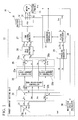
- FIG. 2 is a block diagram of the position sensor according to a first embodiment of the present invention.
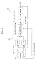
- FIG. 3 is a diagram showing an example of the time variation in the period of the interrupt counter and the rotational period of the motor according to a first embodiment of the present invention.
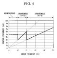
- FIG. 4 is a diagram showing an example of the relationship between the control frequency and the motor frequency according to a first embodiment of the present invention.
- FIG. 5 is a flowchart showing the control decision processing according to a first embodiment of the present invention.
- FIG. 6 is a flowchart showing the synchronization control processing according to a first embodiment of the present invention.
- FIG. 7 is a diagram showing an example of the conditions for transitioning between synchronous control and asynchronous control, and the respective transitioning conditions for processing to increase or decrease the multiplier in synchronization processing.
- FIG. 8 is a flowchart showing the processing for phase difference detection according to a first embodiment of the present invention.
- FIG. 9 is a flowchart showing the control interrupt processing according to a first embodiment of the present invention.
- FIGS. 10A through 10C are diagrams showing the phase of the carrier signal and the change in the induction voltage of the motor according to a first embodiment of the present invention.
- FIGS. 11A through 11C are diagrams showing the time variation in the current amplitude of the various phase currents of the motor according to a first embodiment of the present invention.
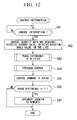
- FIG. 12 is a flowchart showing the control interrupt processing according to a modification of the embodiments of the present invention.
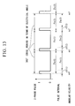
- FIG. 13 is a diagram showing one example of the Z-phase pulse according to a modification of the embodiments of the present invention.
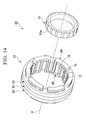
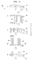
- FIG. 14 is a disassembled diagonal perspective of a claw pole type motor according to a modification of the embodiments of the present invention.
- FIG. 15 is a radial cross-sectional view of the essential components of the stator in a claw pole type motor according to a modification of the embodiments of the present invention.
- FIG. 16 is a disassembled diagonal perspective of an essential component of the stator in a claw pole type motor according to a modification of the embodiments of the present invention.
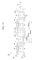
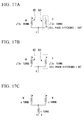
- FIG. 17A is a diagram showing the connection state of the respective annular coils of the stator in the claw pole type motor shown in FIG. 14 ;
- FIG. 17B is a diagram showing the connection state of the respective annular coils of the stator in the claw pole type motor shown in FIG. 14 ;
- FIG. 17C is a diagram showing the connection state of the respective annular coils of a three-phase (U-phase, V-phase and W-phase) stator.
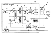
- a motor control apparatus 10 is provided with a power drive unit (PDU) 12 , which employs a battery 11 as a direct current source, and a controller 13 , as shown in FIG. 1 .
- PDU power drive unit
- This motor control apparatus 10 is installed in a hybrid vehicle or electric vehicle that is equipped with a motor M as the drive source, for example.
- the power drive unit (PDU) 12 receives control commands output from the controller 13 and carries out the driving and regenerating operations of the motor M.
- the PDU 12 includes, for example, a PWM inverter by pulse width modulation (PWM) having a bridge circuit with a plurality of switching elements of transistors connected by bridges, and the high voltage battery 11 for supplying and receiving electric energy to and from the motor M is connected to the PDU 12 .
- PWM pulse width modulation
- the PDU 12 switches the ON (conducting)/OFF (cutoff) state of the respective paired transistors at each phase at the PWM inverter, based on a gate signal (i.e., PWM signal), which is a switching command that is input from the controller 13 .
- PWM signal a gate signal
- the PDU 12 converts DC power supplied from the battery 11 to three-phase AC power, performs successive communication of current to three-phase stator windings, and thus passes alternating currents of U-phase current Iu, V-phase current Iv and W-phase current Iw through the each phase of the stator windings.
- the controller 13 carries out feedback control of current on d-q coordinates that form rotating orthogonal coordinates. For example, the controller 13 calculates the d-axis target current Idc and the q-axis target current Iqc from a torque command Tqc which is set in response to the initiation of acceleration relating to an acceleration operation by the driver; calculates the three-phase output voltages Vu, Vv and Vw based on the d-axis target current Idc and the q-axis target current Iqc; inputs a PWM signal, which is a gate signal, to the PDU 12 in accordance with the respective phase output voltages Vu, Vv and Vw; and controls so that the respective deviations between the d-axis current Id and the q-axis current Iq, which are obtained by converting the detection values of the respective phase currents Iu, Iv and Iw that are actually supplied from the PDU 12 to the motor control apparatus 10 on the d-q coordinates, and the d-axis target current
- the controller 13 when driving of the motor M, the controller 13 generates gate signals (i.e., pulse width modulating signals) which are switching commands consisting of pulses for ON/OFF driving of the switching elements of the PWM inverter.
- gate signals i.e., pulse width modulating signals
- These gate signals are generated by using pulse width modulation based on the respective phase output voltages Vu, Vv and Vw, which have a sinusoidal waveform, and a carrier signal, which is a triangular wave or the like, and has a phase and frequency in accordance with the control of a synchronous controller 31 explained below.
- duty cycle of the pulse for ON/OFF driving of each transistor UH/UL, VH/VL, and WH/WL using pulse width modulation (PWM), i.e., the map (data) of the ON/OFF ratio, is stored in advance in the controller 13 .
- the controller 13 receives the input of the detection signals (U-phase detection current Ius, W-phase detection current Iws, etc., for example) output from a current sensor 14 which detects at least any two of the respective phase currents Iu, Iv and Iw supplied from the PDU 12 to the each phase of the stator windings of the motor M (U-phase current Iu, W-phase current Iw, etc., for example); the detection signals output from a position sensor 15 that detects the rotation angle ⁇ m of the rotor of the motor M (i.e., the rotational position of the rotation axis of motor M, which is the rotation angle of the magnetic pole of the rotor from a specific standard rotational position) which is used in coordinate conversion processing, etc.; and the detection signals output from a voltage sensor (not shown in the figures) that detects the terminal voltage (power source voltage) of the battery 11 .
- a voltage sensor not shown in the figures
- the position sensor 15 is provided with a resolver 15 a and a R/D (resolver/digital) converter 15 b .
- An exciting voltage E sinc ⁇ t is supplied from an exciting circuit (not shown in the figures) to the resolver 15 a , and two output signals (K ⁇ E sin ⁇ t ⁇ sin ⁇ and K ⁇ E sin ⁇ t ⁇ cos ⁇ ) in accordance with the rotation angle ⁇ output from the resolver 15 a are input to the R/D converter 15 b .
- the difference (K ⁇ E sin ⁇ t ⁇ sin( ⁇ )) between the value obtained by multiplying (cos ⁇ ) to one of the output signals (K ⁇ E sin ⁇ t ⁇ sin ⁇ ), and the value obtained by multiplying (sin ⁇ ) to the other output signal (K ⁇ E sin ⁇ t ⁇ cos ⁇ ), is input to a synchronous rectification circuit.
- the signal (K ⁇ E ⁇ sin( ⁇ )) which is output after synchronous rectification in accordance with the exciting voltage E sin ⁇ t in the synchronous rectification circuit is input to a voltage controlled oscillator (VCO), and the signal output from this voltage controlled oscillator is input to a counter.
- the R/D (resolver/digital) converter 15 b outputs a pulse train for the Z-phase, which is the origin phase.
- the controller 13 executes current feedback control on a control period which is the same as the period of the carrier signal that is employed in pulse width modulation processing at a PWM signal generator 27 , explained below, and obtains detection values for the respective phase currents Iu, Iv and Iw at a sampling period that is the same as the period of the carrier signal.
- the controller 13 When repeatedly executing sequential control processing in current feedback control, the controller 13 carries out synchronization control to synchronize this control period to the rotational period of the motor M.
- This controller 13 is provided with, for example, a target current setting unit 21 ; a current deviation calculator 22 ; a current controller 23 , a non-interference controller 24 ; a voltage corrector 25 , a dq-3 phase converter 26 ; a PWM signal generator 27 ; a filter processor 28 ; a 3 phase-dq converter 29 ; a rotational speed calculator 30 ; and a synchronization controller 31 .
- the target current setting member 21 calculates a current command for specifying the respective phase currents Iu, Iv and Iw that are supplied from the PDU 12 to the motor M.
- This current command is output to the current deviation calculator 22 as the d-axis target current Idc and the q-axis target current Iqc on the rotating orthogonal coordinates.
- the d-q coordinates that form these rotating orthogonal coordinates sets, for example, a direction of a magnetic flux of a field pole by the permanent magnet of the rotor in a d-axis (a field axis) and sets a direction orthogonal to this d-axis in a q-axis (a torque axis), and rotates in synchrony with the rotation phase of the rotor.
- the d-axis target current Idc and the q-axis target current Iqc which are DC signals, are provided as current commands to the AC signals supplied from the PDU 12 to the respective phases of motor M.
- the current deviation calculator 22 is provided with a d-axis current deviation calculator 22 a for calculating the deviation ⁇ Id between the d-axis target current Idc and the d-axis current Id; and a q-axis current deviation calculator 22 b for calculating the deviation ⁇ Iq between the q-axis target current Iqc and the q-axis current Iq.
- the current controller 23 is provided with a d-axis current PI controller 23 a which uses PI (proportional-plus-integral) operations to control and amplify the deviation ⁇ Id and calculate the d-axis voltage command ⁇ Vd; and a q-axis current PI controller 23 b which uses PI (proportional-plus-integral) operations to control and amplify the deviation ⁇ Iq and calculate the q-axis voltage command ⁇ Vq.
- PI proportional-plus-integral
- the non-interference controller 24 calculates the d-axis compensatory term Vdc and the q-axis compensatory term Vqc for canceling out the various interference components imparted on the d-axis and the q-axis, in order to independently control the d-axis and the q-axis by canceling out the motional electromotive forces that interfere between the d-axis and the q-axis.
- the voltage corrector 25 is provided with a d-axis voltage adder 25 a which adds the d-axis voltage command ⁇ Vd and the d-axis compensatory term Vdc, and employs the obtained value as the d-axis voltage command Vd; and a q-axis voltage adder 25 b which adds the q-axis voltage command ⁇ Vq and the q-axis compensatory term Vqc, and employs the obtained value as the q-axis voltage command Vq.
- the dq-3 phase converter 26 uses an rotation angle ⁇ m which corresponds to the rotational position of the motor M that is input from the position sensor 15 to convert the d-axis voltage command Vd and the q-axis voltage command Vq on the d-q coordinates, to a U-phase output voltage Vu, a V-phase output voltage Vv and a W-phase output voltage Vw, which are the voltage command values, on a three-phase AC coordinates which are static coordinates.
- the PWM signal generator 27 generates a gate signal (i.e., a PWM signal) which is a switching command consisting of pulses for ON/OFF driving of the switching elements of the PWM inverter of the PDU 12 , using pulse width modulation based on the sinusoidal respective phase output voltages Vu, Vv and Vw, and the carrier signal which consists of a triangular wave.
- a gate signal i.e., a PWM signal
- the filter processor 28 carries out filter processing, such as the removal of high frequency components and the like, of the detection signals Ius and Iws for the respective phase currents that are detected by the respective current sensors 14 , 14 , and extracts the respective phase currents Iu and Iw as physical quantities in response to the control of the synchronous controller 31 , explained below.
- the 3 phase-dq converter 29 calculates the d-axis current Id and the q-axis current Iq on the rotating coordinates by rotation phase of the motor M, i.e., on the d-q coordinates.
- the rotational speed calculator 30 calculates the revolutions NM of the motor M from the detection signal output by the position sensor 15 .
- the synchronous controller 31 When repeatedly executing the sequential control processing in current feedback control, the synchronous controller 31 detects the phase difference between the Z-phase pulse output from the position sensor 15 , which is the origin phase, i.e., the pulse output at a 360° (edeg) period in terms of electrical angle synchronized with the rotation of the motor M, and the interrupt counter which is based on a specified multiplier set in advance in response to the revolutions of the motor M and the control period for current feedback control. The synchronous controller 31 then executes synchronous control when the rotational frequency of the motor M (i.e., the product of revolutions and polar pairs) is equal to or greater than a specific frequency and the phase difference is equal to or less than a specific value.
- the rotational frequency of the motor M i.e., the product of revolutions and polar pairs
- the synchronous controller 31 is provided with an addition-type interrupt counter in which data of specific multipliers N in response to the revolutions of the motor M are recorded in advance, and the counter value of which is initialized at each period of the carrier signal.
- a period of the carrier signal i.e., a period of the interrupt counter
- Tc ( T ⁇ k ⁇ t )/ N [Equation 7]
- phase differences ⁇ t (n) and ⁇ t (n+1), which are adjacent on a time series and where n is an optional natural number, can be described as shown in equation (8) below.
- the specified coefficient k is set to 1
- the phase difference ⁇ t becomes zero in the subsequent processing in which the period Tc of the carrier signal is set in accordance with equation (7) above.
- the specified multiplier N which is preset in response to the revolutions of the motor M, is set so as to change in a decreasing trend toward a specified lower limit value, as the rotational frequency of the motor M (i.e., motor frequency) increases a specified upper limit period and above.
- the control frequency of the current feedback control i.e., the carrier signal frequency
- the specified value 5e without synchronous control being carried out.
- the multiplier N is decreased to 6 while maintaining execution of synchronous control, and the control frequency of the current feedback control, i.e., the carrier signal frequency, changes in accordance with equation (7).
- the synchronous controller 31 sets specific upper limit and lower limit frequencies for the control frequency (or specific lower limit and upper limit periods for the control period) for each specified multiplier N in response to the revolutions of the motor M.
- the multiplier N is decreased when the control frequency exceeds a specified upper limit frequency (or when the control period is less than a specified lower limit period) and the multiplier N is equal to or greater than a specified lower limit.
- the multiplier N is increased when the control frequency is equal to or less than a lower limit frequency (or when the control period is equal to or greater than the specific upper limit period).
- the synchronous controller 31 sets the multiplier N so that the control frequency of the current feedback control, i.e., the frequency of the carrier signal, does not exceed the specified response thresholds of the control apparatus or the various switching elements of the PDU 12 for example, even in the case where the control frequency is increasing accompanying an increase in the motor frequency in accordance with equation (7).
- the synchronous controller 31 prohibits execution of synchronous control when the control period of the current feedback control is less than a specified lower limit period and the multiplier N in response to the revolutions of motor M is less than a specified lower limit value.
- the synchronous controller 31 When executing synchronous control, the synchronous controller 31 extracts average values for the respective phase currents Iu and Iw over a specified period (a 360° (edeg) period in terms of electrical angle, for example) as physical quantities at the filter processor 28 , based on the detection signals Ius and Iws for respective phase currents that are detected by the respective current sensors 14 , 14 over a specified period (a 360° (edeg) period in terms of electrical angle, for example) that relates to the rotational period of the motor M. Next, based on these average values, the synchronous controller 31 provides settings so that current feedback control is performed.
- the motor control apparatus 10 according to this embodiment is provided with the above-described design. The operations thereof will now be explained with reference to the accompanying figures.
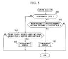
- step S 01 shown in FIG. 5 a decision is made as to whether or not a synchronous control non-execution state, wherein the control frequency of current feedback control is being maintained at a suitable value, is present.
- step S 04 the process proceeds to step S 04 .
- step S 02 the process proceeds to step S 02 .
- step S 02 a decision is made as to whether or not the motor frequency, which is detected in accordance with the detection signals output from the position sensor 15 , is equal to or greater than the specified frequency and the phase difference is equal to or less than a specified value.
- step S 03 synchronous control is initiated and sequential processing is then concluded.
- step S 04 a decision is made as to whether or not the control period of the current feedback control is less than a specified lower limit period and the multiplier in response to the revolutions of the motor M are less than a specified lower limit value.
- step S 05 a synchronous control non-execution state is set, and sequential processing is concluded.
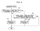
- step S 03 The processing for setting the multiplier in the synchronous control in step S 03 will now be explained.
- step S 11 shown in FIG. 6 for example, a decision is made as to whether or not the control period of current feedback control is equal to or greater than a specified upper limit period that is preset in accordance with the multiplier at that time point.
- step S 13 the process proceeds to step S 13 .
- step S 12 the process proceeds to step S 12 .
- step S 12 a multiplier map or the like which was preset in accordance with the motor frequency and the control frequency is referenced, the multiplier is increased and sequential processing is concluded.
- step S 13 a decision is made as to whether or not the control period of current feedback control is less than a specified lower limit period that is preset in accordance with the multiplier at that time point, and whether or not the multiplier corresponding to the motor frequency and the control period at that time point is equal to or greater than a specified lower limit value.
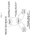
- FIG. 7 shows an example of the conditions when transitioning between synchronous and asynchronous control, and an example of the conditions for the various transitions with respect to increasing and decreasing the multiplier in synchronous control.
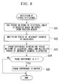
- step S 21 shown in FIG. 8 for example, one period in terms of electrical angle of the rotational period of the motor M is detected based on the Z-phase pulse output from the position sensor 15 .
- step S 22 the specified multiplier set in response to the revolutions of the motor M is obtained, and the period of the interrupt counter (i.e., the period of the carrier signal) is multiplied by the multiplier, to calculate the multiplier period.
- the period of the interrupt counter i.e., the period of the carrier signal
- step S 23 the phase difference between one period in terms of electrical angle of the rotational period of the motor M and the multiplier period of the interrupt counter is detected.
- step S 24 A decision is then made in step S 24 as to whether or not the phase difference is a value other than zero.
- step S 25 data on the phase difference is output in step S 25 .
- Control interrupt processing is processing performed during synchronous control execution, in which sequential control processing in current feedback control is repeatedly executed for each control period that is the same as the period of the carrier signal.
- a decision is made as to whether or not it is the timing for initializing the counter value based on the counter value of the interrupt counter reaching a specified upper limit value, i.e., a decision is made as to whether or not a control interrupt timing is present.
- step S 31 the decision processing in step S 31 is repeated.
- step S 32 the process proceeds to step S 32 .
- step S 32 the detection signals Ius and Iws for the respective phase currents that were detected by respective current sensors 14 , 14 , and various control quantity data such as phase difference etc., detected in the above steps S 21 to S 25 are acquired.
- step S 33 current feedback control is executed using the average values of the respective phase currents Iu and Iw over a specified period (a 360° (edeg) period in terms of electrical angle, for example), based on the detection signals Ius and Iws acquired over a specified period (a 360° (edeg) period in terms of electrical angle, for example) relating to the rotational period of the motor M.
- step S 34 the control commands under current feedback control are output, i.e., the U-phase output voltage Vu, V-phase output voltage Vv and W-phase output voltage Vw, which are the voltage command values on three-phase AC coordinates which are static coordinates, are output.
- step S 35 a decision is made as to whether or not the acquired phase difference is a value other than zero.
- step S 36 the process proceeds to step S 36 , and the counter value of the interrupt counter is initialized and the interrupt counter period (i.e., the period of the carrier signal) is newly set according to the above equation (7) for example, after which sequential processing is concluded.
- the carrier signal frequency so that it becomes the specified multiplier for one period in terms of electrical angle of the rotational period of the motor M, it is possible to prevent the frequency of the carrier signal from becoming excessively large accompanying an increase in the rotational frequency of the motor M, and to prevent a deterioration in the stability of motor control caused by the induction voltage of motor M and higher harmonic components that are included in the various phase currents of motor M. As a result, it is possible to suitably increase the output while decreasing the size of the motor M.
- the control period is synchronized with the rotational period of the motor M.
- current feedback control is carried out using the average values of the respective phase currents Iu and Iw over a specified period (a 360° (edeg) period in terms of electrical angle, for example), based on the detection signals Ius and Iws acquired over a specified period (a 360° (edeg) period in terms of electrical angle, for example) relating to the rotational period of the motor M.
- a 360° (edeg) period in terms of electrical angle for example
- the period Tc of the carrier signal is set based on a specified coefficient k that is equal to or less than 1 and greater than zero in the above equation (7). Accordingly, by setting the specified coefficient k to be less than one when the rotation speed of the motor M varies, it is possible to suitably set the control gain when converging the phase difference ⁇ t to zero, and to prevent oscillations, etc., from arising in the phase difference ⁇ t.
- the carrier signal frequency i.e., the interrupt counter frequency
- the current amplitudes of the respective phase currents U, V, W phase currents
- the period of the carrier signal changes from a suitable period T 1 to a period T 2 (>T 1 ) and, as shown in FIGS. 10B and 11B for example, the deviation in the current amplitude of the respective phase currents (U, V, W phase currents) increases due to the phase difference between the rotational period of the motor M and the period of the carrier signal, i.e., the timing at which the counter value of the interrupt counter becomes zero. As a result, current feedback control becomes unstable.
- the phase difference detected in steps S 21 to S 25 was obtained in the control interrupt processing.
- the present invention is not limited thereto; rather, it is also acceptable to detect the phase difference in the control interrupt processing, for example.
- a decision is first made in step S 41 as to whether or not the timing is present for initializing the counter value because the counter value of the interrupt counter has reached a specified upper limit value, i.e., a decision is made as to whether or not a control interrupt timing is present.
- step S 41 When the decision result is [NO], the decision processing of step S 41 is repeated.
- step S 42 the process proceeds to step S 42 .
- step S 42 various control quantity data, such as the detection signals Ius and Iws for the respective phase currents detected by the respective current sensors 14 , 14 and the detection signals output from position sensor 15 , are acquired.
- step S 43 the phase difference between the rotation angle ⁇ m of the motor M and a specified origin position is detected based on the detection signals output from the position sensor 15 .
- step S 44 current feedback control is executed using the average values of the respective phase currents Iu and Iw over a specified period (the 360° (edeg) period, for example), based on the detection signals Ius and Iws obtained over a specified period (the 360° (edeg) period, for example) relating to the rotational period of the motor M.
- step S 45 the control command in current feedback control is output, i.e., the U-phase output voltage Vu, V-phase output voltage Vv and W-phase output voltage Vw, which are the voltage command values on three-phase AC coordinates which are static coordinates, are output.
- step S 46 a decision is made as to whether or not the detected phase difference is a value other than zero.
- step S 47 the process proceeds to step S 47 , and the counter value of the interrupt counter is initialized and the interrupt counter period (i.e., the period of the carrier signal) is newly set according to the above equation (7) for example, after which sequential processing is concluded.
- synchronous controller 31 is designed to converge the phase difference ⁇ t to zero.
- the present invention is not limited thereto. Rather, for example, the phase difference ⁇ t can be converged to a specified phase difference.
- synchronous controller 31 detected the rotational period of the motor M based on a pulse output from the position sensor 15 .
- the present invention is not limited thereto. Rather, it is acceptable to detect the rotational period of the motor M based on a signal which is synchronized to the rotational period of the motor M.
- the rotational period of the motor M may be detected based on pulses which are output from various sensors such as pulse sensors that are equipped to the internal combustion engine and are capable of outputting a relatively high precision signal.
- synchronous controller 31 it is acceptable for synchronous controller 31 to estimate the rotational period of the motor M in the case where the angular velocity relating to the rotation angle corresponding to the rotational position of the motor M changes, and to carry out synchronous control based on this estimated rotational period.
- the interval between adjacent Z-phase pulses (pulse interval Tw(m), where m is an optional positive integer) on the time series, the pulse which is output from the position sensor 15 , constricts in a manner inversely proportional to the increasing angular velocity (angular velocity ⁇ 0 , ⁇ 1 , ⁇ 2 , ⁇ 3 , . . . ).
- pulse interval Tw(0) is described analytically by the following equation (10) for example, from equation (9), where ⁇ is the angular velocity, ⁇ is the rotation angle, t is time, and a, ⁇ 0 are specified coefficients.
- synchronous controller 31 it is acceptable for synchronous controller 31 to estimate an estimated rotational period of the motor M by assuming that the amount of change in the intervals between adjacent pulses on a time series changes in accordance with a specified ratio k, as shown in the following equation (13) for example.
- synchronous controller 31 it is acceptable for synchronous controller 31 to estimate an estimated rotational period of the motor M by assuming that the interval between adjacent pulses on a time series changes in accordance with a specific ratio, as shown in the following equation (14) for example.
- Tw ⁇ ( n ) Tw ⁇ ( n - 1 ) ⁇ Tw ⁇ ( n - 1 ) Tw ⁇ ( n - 2 ) [ Equation ⁇ ⁇ 14 ]
- motor M is not particularly restricted in the preceding embodiments, and may be, for example, a claw pole type motor, or the like, such as shown in FIGS. 14 through 16 .
- This claw pole type motor 50 is provided with a rotor 51 having a plurality of permanent magnets 51 a , . . . , 51 a , and a multiphase (U-phase, V-phase, W-phase of three phases, for example) stator 52 that generates a rotating magnetic field for rotating the rotor 51 .
- a plurality of approximately rectangular, plate-shaped permanent magnets 51 a , . . . , 51 a are disposed at a specified interval in the circumferential direction on the outer circumferential surface of the rotor 51 , for example.
- the permanent magnets are magnetized in its thickness direction (i.e., in the radial direction of rotor 51 ) with the magnetization directions of the permanent magnets adjacent in the circumferential direction disposed so as to be reversed between adjacent magnets. That is, a permanent magnet 51 a whose outer circumferential side serves as an N-pole is adjacent to another permanent magnet 51 a whose outer circumferential side serves as an S-pole.
- each permanent magnet 51 a is exposed to the inner circumferential surface of the tube-shaped stator 52 which is disposed opposing the outer circumferential of the rotor 51 .
- the stator 52 which generates a rotating magnetic field for rotating a rotor 51 , is provided with a U-phase stator ring 61 , a V-phase stator ring 62 , and a W-phase stator ring 63 for the respective A, B, and C phases, and a U-phase annular coil 64 and a W-phase annular coil 65 for the respective U and W phases.
- the U-phase stator ring 61 is provided with a ring-shaped U-phase yoke 71 and U-phase teeth 72 .
- the U-phase teeth 72 project inward in the radical direction R from positions spaced at a specified interval in the circumferential direction C on the inner circumferential side of the U-phase yoke 71 , and project toward the other direction along the axial direction P, with the cross-sectional shape in the radical direction R being substantially rectangular.
- the U-phase stator ring 61 consisting of the U-phase yoke 71 and U-phase teeth 72 is formed so that its cross-sectional shape in the circumferential direction C is L-shaped.
- the V-phase stator ring 62 is provided with a ring-shaped V-phase yoke 73 and V-phase teeth 74 .
- the V-phase teeth 74 project inward in the radical direction R from positions spaced at a specified interval in the circumferential direction C on the inner circumferential side of the V-phase yoke 73 , and project toward one and the other directions along the axial direction P, with the cross-sectional shape in the radical direction R being substantially rectangular.
- the V-phase stator ring 62 consisting of the V-phase yoke 73 and V-phase teeth 74 is formed so that its cross-sectional shape in the circumferential direction C is T-shaped.
- the W-phase stator ring 63 is provided with a ring-shaped W-phase yoke 75 and W-phase teeth 76 .
- the W-phase teeth 76 project inward in the radical direction R from positions spaced at a specified interval in the circumferential direction C on the inner circumferential side of the W-phase yoke 75 , and project toward one direction along the axial direction P, with the cross-sectional shape in the radical direction R being substantially rectangular.
- the W-phase stator ring 63 consisting of the W-phase yoke 75 and W-phase teeth 76 is formed so that its cross-sectional shape in the circumferential direction C is L-shaped.
- the stator rings 61 , 62 , 63 are connected so that the yokes 71 , 73 , 75 are superimposed along the axial direction P. Further, as shown in FIG. 15 for example, the plurality of teeth 72 , . . . 72 ; 74 , . . . 74 ; 76 , . . . 76 are arranged in the circumferential direction C in a specified order (for example, in the order of U-phase tooth 72 , V-phase tooth 74 , W-phase tooth 76 , etc.). Slots where single phase of the U-phase annular coil 74 is to be disposed are formed between the teeth 72 and 74 that are adjacent in the circumferential direction C.
- Slots where single phase of the W-phase annular coil 65 is to be disposed are formed between the teeth 74 and 76 that are adjacent in the circumferential direction C. Slots where two phases of the U-phase annular coil 64 and W-phase annular coil 65 are to be disposed are formed between the teeth 72 and 76 that are adjacent in the circumferential direction C.
- the respective teeth 72 , 74 , and 76 of the respective stator rings 61 , 62 , and 63 have identical widths in the axial direction and the circumferential direction, for example.
- the interval between the respective teeth 72 , 74 , and 76 adjacent in the circumferential direction C is set to a value corresponding to the number of annular coils 64 and 65 disposed in the slots (for example, a value proportional to the number of coils).
- the interval C 1 between the teeth 72 and 74 and between the teeth 74 and 76 in which the annular coils 64 and 65 are singly disposed is set to a value less than an interval C 2 between the teeth 72 and 76 in which both annular coils 314 and 315 of two phases are disposed (for example, 1 ⁇ 2 of the interval C 2 between the teeth 72 and 76 ).
- the annular coils 64 and 65 surround the circumference around the axis while meandering in a crank shape within the circumferential surface, to be thereby provided with a plurality of U-phase meandering portions 81 and W-phase meandering portions 82 , respectively.
- the width of the meandering portions 81 and 82 in the circumferential direction C is set to an electrical angle of 120°, as shown, for example, in FIG. 14 .
- the meandering portions 81 and 82 are configured to project in mutually different directions (that is, the one side and the other side along the axis P, which are mutually opposing directions).
- the U-phase annular coil 64 and the W-phase annular coil 65 are disposed at relatively shifted positions along the circumferential direction C so as to have a phase difference of 240° (edeg) in terms of electrical angle.
- the W-phase meandering portion 82 that is adjacent on the one side in the circumferential direction C has a phase difference of 240° (edeg) in terms of electrical angle
- the W-phase meandering portion 82 that is adjacent on the other side in the circumferential direction C has a phase difference of 120° (edeg) in terms of electrical angle.
- the meandering portions 81 and 82 which project in mutually opposite directions, are alternately arranged along the circumferential direction C so that the annular coils 64 and 65 of the two phases are disposed so as not to mutually cross.
- One U-phase tooth 72 of the U-phase stator ring 61 is disposed in U-phase meandering portion 81 of the U-phase annular coil 64 .
- One W-phase tooth 76 of the W-phase stator ring 63 is disposed in W-phase meandering portion 82 of the W-phase annular coil 65 .
- One V-phase tooth 74 of the V-phase stator ring 62 is disposed between U-phase meandering portion 81 and W-phase meandering portion 82 that are adjacent in the circumferential direction C.
- the annular coils 64 and 65 of two phases which are disposed so as to weave between the teeth 72 and 74 , between the teeth 74 and 76 , or between the teeth 72 and 76 adjacent in the circumferential direction C, are formed so as to have so-called short-pitch wave windings of not more than 120° (edeg) in terms of electrical angle.
- the annular coils 64 and 65 of two phases having a phase difference (coil phase difference) of 240° (edeg) in terms of electrical angle are, as shown in FIG. 17A for example, connected in a V-shape, and energized with sinusoidal waves having a mutual phase difference of 120°.
- a rotating magnetic field is produced similar to that of a three-phase stator having three-phase coils of, U, V, and W phases are connected in a Y-shape and energized by sinusoidal waves with a mutual phase difference of 120°.
- a rotating magnetic field can be produced similarly to that of a three-phase stator in which its coils of U, V, and W phases are connected in a Y-shape and energized by sinusoidal waves with a mutual phase difference of 120°.
Landscapes
- Engineering & Computer Science (AREA)
- Power Engineering (AREA)
- Control Of Ac Motors In General (AREA)
- Control Of Motors That Do Not Use Commutators (AREA)
Abstract
Description
Tc=(T−k·Δt)/N [Equation 7]
Δt(n+1)=(1−k)·Δt(n) [Equation 8]
ΔT(n)=0 [Equation 11]
ΔT(n)=ΔT(n−1) [Equation 12]
Claims (12)
Applications Claiming Priority (2)
| Application Number | Priority Date | Filing Date | Title |
|---|---|---|---|
| JP2007114047A JP4909797B2 (en) | 2007-04-24 | 2007-04-24 | Motor control device |
| JP2007-114047 | 2007-04-24 |
Publications (2)
| Publication Number | Publication Date |
|---|---|
| US20080265831A1 US20080265831A1 (en) | 2008-10-30 |
| US7872435B2 true US7872435B2 (en) | 2011-01-18 |
Family
ID=39886135
Family Applications (1)
| Application Number | Title | Priority Date | Filing Date |
|---|---|---|---|
| US12/107,358 Expired - Fee Related US7872435B2 (en) | 2007-04-24 | 2008-04-22 | Motor control apparatus |
Country Status (2)
| Country | Link |
|---|---|
| US (1) | US7872435B2 (en) |
| JP (1) | JP4909797B2 (en) |
Cited By (6)
| Publication number | Priority date | Publication date | Assignee | Title |
|---|---|---|---|---|
| US20100013467A1 (en) * | 2008-07-18 | 2010-01-21 | Aisin Seiki Kabushiki Kaisha | Rotation sensor |
| US20110056771A1 (en) * | 2009-09-08 | 2011-03-10 | Kabushiki Kaisha Yaskawa Denki | Elevator control device |
| US20110248656A1 (en) * | 2010-04-08 | 2011-10-13 | Omron Automotive Electronics Co., Ltd. | Motor drive device |
| US20130076128A1 (en) * | 2011-09-28 | 2013-03-28 | Caterpillar, Inc. | Active Switching Frequency Modulation |
| US20130133498A1 (en) * | 2010-08-13 | 2013-05-30 | Bizerba Gmbh & Co. Kg | Slicer |
| US20150015171A1 (en) * | 2013-07-12 | 2015-01-15 | Denso Corporation | Apparatus for carrying out improved control of rotary machine |
Families Citing this family (20)
| Publication number | Priority date | Publication date | Assignee | Title |
|---|---|---|---|---|
| JP5176594B2 (en) * | 2008-02-27 | 2013-04-03 | 株式会社デンソー | Rotating machine control device |
| JP5396910B2 (en) * | 2009-02-25 | 2014-01-22 | 日産自動車株式会社 | Motor control device |
| JP2010202332A (en) * | 2009-03-03 | 2010-09-16 | Murata Machinery Ltd | Textile machine |
| JP5428460B2 (en) * | 2009-03-30 | 2014-02-26 | 日産自動車株式会社 | Electric motor control device and electric motor control method |
| JP4803286B2 (en) | 2009-07-31 | 2011-10-26 | 株式会社デンソー | Vehicle drive motor control device |
| US9071188B2 (en) * | 2009-09-04 | 2015-06-30 | Black & Decker Inc. | Protective redundant subsystem for power tools |
| US8487563B2 (en) | 2009-11-27 | 2013-07-16 | Denso Corporation | Drive motor control apparatus for vehicle, motor control system, method for correcting rotation angle of motor, program for performing the same, rotation detecting apparatus |
| JP5035641B2 (en) | 2009-11-30 | 2012-09-26 | アイシン・エィ・ダブリュ株式会社 | Control device for motor drive device |
| KR101101471B1 (en) * | 2010-01-08 | 2012-01-03 | 엘에스산전 주식회사 | Apparatus and method for controlling operation of inverter system |
| ES2736164T3 (en) * | 2011-01-18 | 2019-12-26 | Siemens Ag | Controller device for the control of a power converter device |
| JP2016046859A (en) * | 2014-08-20 | 2016-04-04 | 株式会社リコー | Motor drive control apparatus and motor drive control method |
| JP6447530B2 (en) * | 2016-01-29 | 2019-01-09 | オムロン株式会社 | Signal processing apparatus, signal processing apparatus control method, control program, and recording medium |
| JP2019161704A (en) * | 2018-03-07 | 2019-09-19 | 本田技研工業株式会社 | Motor controller |
| US10913550B2 (en) | 2018-03-23 | 2021-02-09 | The Boeing Company | System and method for position and speed feedback control |
| US10830591B2 (en) | 2018-03-23 | 2020-11-10 | The Boeing Company | System and method for dual speed resolver |
| US10911061B2 (en) * | 2018-03-23 | 2021-02-02 | The Boeing Company | System and method for demodulation of resolver outputs |
| DE102018130972A1 (en) * | 2018-12-05 | 2020-06-10 | HELLA GmbH & Co. KGaA | Device, arrangement and method for determining an angle between a rotor and a stator |
| WO2020161786A1 (en) * | 2019-02-05 | 2020-08-13 | 東芝三菱電機産業システム株式会社 | Power converter |
| US10587185B1 (en) * | 2019-04-16 | 2020-03-10 | Ford Global Technology, Llc | Dynamic carrier waveform modification to avoid concurrent turn-on/turn-off switching |
| CN115327891B (en) * | 2022-09-16 | 2024-05-24 | 成都奥瑞科电子科技有限公司 | Motor drive control system based on sense and calculation integration |
Citations (6)
| Publication number | Priority date | Publication date | Assignee | Title |
|---|---|---|---|---|
| JPH05161364A (en) | 1991-12-03 | 1993-06-25 | Toshiba Corp | Inverter |
| JPH07163189A (en) | 1993-12-08 | 1995-06-23 | Toyota Motor Corp | Pwm controller for motor |
| US5532569A (en) * | 1987-06-03 | 1996-07-02 | Hitachi, Ltd. | Inverter control apparatus |
| US20050201129A1 (en) * | 2004-03-12 | 2005-09-15 | Hitachi, Ltd. | Control apparatus, dual chip inverter and single chip inverter of AC motors |
| US20060184213A1 (en) * | 2005-02-15 | 2006-08-17 | Griffith Glen A | Integrated phase-shift power control transmitter for use with implantable device and method for use of the same |
| US7166975B2 (en) * | 2005-02-18 | 2007-01-23 | Matsushita Electric Industrial Co., Ltd. | Apparatus and method for driving the multiphase motor using the magnetic pole position detector |
Family Cites Families (3)
| Publication number | Priority date | Publication date | Assignee | Title |
|---|---|---|---|---|
| JPS6055884A (en) * | 1983-09-05 | 1985-04-01 | Shinko Electric Co Ltd | Controller of commutatorless motor |
| JP4217384B2 (en) * | 2001-03-28 | 2009-01-28 | 東芝マイクロエレクトロニクス株式会社 | Motor drive device by PWM control system |
| JP2006034022A (en) * | 2004-07-20 | 2006-02-02 | Nissan Motor Co Ltd | Ac motor controller |
-
2007
- 2007-04-24 JP JP2007114047A patent/JP4909797B2/en active Active
-
2008
- 2008-04-22 US US12/107,358 patent/US7872435B2/en not_active Expired - Fee Related
Patent Citations (6)
| Publication number | Priority date | Publication date | Assignee | Title |
|---|---|---|---|---|
| US5532569A (en) * | 1987-06-03 | 1996-07-02 | Hitachi, Ltd. | Inverter control apparatus |
| JPH05161364A (en) | 1991-12-03 | 1993-06-25 | Toshiba Corp | Inverter |
| JPH07163189A (en) | 1993-12-08 | 1995-06-23 | Toyota Motor Corp | Pwm controller for motor |
| US20050201129A1 (en) * | 2004-03-12 | 2005-09-15 | Hitachi, Ltd. | Control apparatus, dual chip inverter and single chip inverter of AC motors |
| US20060184213A1 (en) * | 2005-02-15 | 2006-08-17 | Griffith Glen A | Integrated phase-shift power control transmitter for use with implantable device and method for use of the same |
| US7166975B2 (en) * | 2005-02-18 | 2007-01-23 | Matsushita Electric Industrial Co., Ltd. | Apparatus and method for driving the multiphase motor using the magnetic pole position detector |
Cited By (11)
| Publication number | Priority date | Publication date | Assignee | Title |
|---|---|---|---|---|
| US20100013467A1 (en) * | 2008-07-18 | 2010-01-21 | Aisin Seiki Kabushiki Kaisha | Rotation sensor |
| US8164324B2 (en) * | 2008-07-18 | 2012-04-24 | Aisin Seiki Kabushiki Kaisha | Rotation sensor |
| US20110056771A1 (en) * | 2009-09-08 | 2011-03-10 | Kabushiki Kaisha Yaskawa Denki | Elevator control device |
| US8348020B2 (en) * | 2009-09-08 | 2013-01-08 | Kabushiki Kaisha Yaskawa Denki | Elevator control device with carrier frequency switch circuit |
| US20110248656A1 (en) * | 2010-04-08 | 2011-10-13 | Omron Automotive Electronics Co., Ltd. | Motor drive device |
| US8446115B2 (en) * | 2010-04-08 | 2013-05-21 | Omron Automotive Electronics Co., Ltd. | Motor drive device |
| US20130133498A1 (en) * | 2010-08-13 | 2013-05-30 | Bizerba Gmbh & Co. Kg | Slicer |
| US9815218B2 (en) * | 2010-08-13 | 2017-11-14 | Bizerba Gmbh & Co. Kg | Slicer with pulse-width modulation control unit |
| US20130076128A1 (en) * | 2011-09-28 | 2013-03-28 | Caterpillar, Inc. | Active Switching Frequency Modulation |
| US20150015171A1 (en) * | 2013-07-12 | 2015-01-15 | Denso Corporation | Apparatus for carrying out improved control of rotary machine |
| US9325274B2 (en) * | 2013-07-12 | 2016-04-26 | Denso Corporation | Apparatus for carrying out improved control of rotary machine |
Also Published As
| Publication number | Publication date |
|---|---|
| JP2008271740A (en) | 2008-11-06 |
| US20080265831A1 (en) | 2008-10-30 |
| JP4909797B2 (en) | 2012-04-04 |
Similar Documents
| Publication | Publication Date | Title |
|---|---|---|
| US7872435B2 (en) | Motor control apparatus | |
| EP2770627B1 (en) | Motor control device and motor control method | |
| US7514896B2 (en) | Method of estimating magnetic pole position in synchronous motor | |
| JP4205157B1 (en) | Electric motor control device | |
| US9350282B2 (en) | Motor control device and motor control method | |
| JP4754417B2 (en) | Control device for permanent magnet type rotating electrical machine | |
| US6771039B2 (en) | Motor control apparatus and method | |
| EP2770630B1 (en) | Motor control device and motor control method | |
| KR101046802B1 (en) | Control device of AC rotor and electric constant measurement method of AC rotor using this controller | |
| US9112436B2 (en) | System for controlling controlled variable of rotary machine | |
| WO2013021998A1 (en) | Control device | |
| JP5488845B2 (en) | AC motor control device | |
| JP2010093931A (en) | Device and method for controlling permanent magnet-type synchronous motor | |
| JP4923962B2 (en) | Control device for multi-phase rotating machine | |
| US11309817B2 (en) | Control device of rotating machine, and control device of electric vehicle | |
| US20130278186A1 (en) | Ac motor control apparatus | |
| JP5222630B2 (en) | Motor control device | |
| JP2006050705A (en) | Motor control unit | |
| JP6422796B2 (en) | Synchronous machine control device and drive system | |
| JP4485840B2 (en) | Control device for claw pole type motor | |
| JP4526628B2 (en) | AC motor control device | |
| US20240305233A1 (en) | Control device for electric motor | |
| JP5038008B2 (en) | Motor control device | |
| JP2009296834A (en) | Motor controller | |
| JP2010233390A (en) | Motor control drive device |
Legal Events
| Date | Code | Title | Description |
|---|---|---|---|
| AS | Assignment |
Owner name: HONDA MOTOR CO., LTD, JAPAN Free format text: ASSIGNMENT OF ASSIGNORS INTEREST;ASSIGNORS:IMAI, NOBUYUKI;MURAYAMA, YOSHINARI;INOUE, JUNJI;REEL/FRAME:020839/0740 Effective date: 20080408 |
|
| FEPP | Fee payment procedure |
Free format text: PAYOR NUMBER ASSIGNED (ORIGINAL EVENT CODE: ASPN); ENTITY STATUS OF PATENT OWNER: LARGE ENTITY |
|
| STCF | Information on status: patent grant |
Free format text: PATENTED CASE |
|
| FPAY | Fee payment |
Year of fee payment: 4 |
|
| MAFP | Maintenance fee payment |
Free format text: PAYMENT OF MAINTENANCE FEE, 8TH YEAR, LARGE ENTITY (ORIGINAL EVENT CODE: M1552) Year of fee payment: 8 |
|
| FEPP | Fee payment procedure |
Free format text: MAINTENANCE FEE REMINDER MAILED (ORIGINAL EVENT CODE: REM.); ENTITY STATUS OF PATENT OWNER: LARGE ENTITY |
|
| LAPS | Lapse for failure to pay maintenance fees |
Free format text: PATENT EXPIRED FOR FAILURE TO PAY MAINTENANCE FEES (ORIGINAL EVENT CODE: EXP.); ENTITY STATUS OF PATENT OWNER: LARGE ENTITY |
|
| STCH | Information on status: patent discontinuation |
Free format text: PATENT EXPIRED DUE TO NONPAYMENT OF MAINTENANCE FEES UNDER 37 CFR 1.362 |
|
| FP | Lapsed due to failure to pay maintenance fee |
Effective date: 20230118 |