JP4909797B2 - Motor control device - Google Patents
Motor control device Download PDFInfo
- Publication number
- JP4909797B2 JP4909797B2 JP2007114047A JP2007114047A JP4909797B2 JP 4909797 B2 JP4909797 B2 JP 4909797B2 JP 2007114047 A JP2007114047 A JP 2007114047A JP 2007114047 A JP2007114047 A JP 2007114047A JP 4909797 B2 JP4909797 B2 JP 4909797B2
- Authority
- JP
- Japan
- Prior art keywords
- motor
- period
- rotation
- phase
- control
- Prior art date
- Legal status (The legal status is an assumption and is not a legal conclusion. Google has not performed a legal analysis and makes no representation as to the accuracy of the status listed.)
- Active
Links
Images
Classifications
-
- H—ELECTRICITY
- H02—GENERATION; CONVERSION OR DISTRIBUTION OF ELECTRIC POWER
- H02P—CONTROL OR REGULATION OF ELECTRIC MOTORS, ELECTRIC GENERATORS OR DYNAMO-ELECTRIC CONVERTERS; CONTROLLING TRANSFORMERS, REACTORS OR CHOKE COILS
- H02P6/00—Arrangements for controlling synchronous motors or other dynamo-electric motors using electronic commutation dependent on the rotor position; Electronic commutators therefor
- H02P6/14—Electronic commutators
- H02P6/16—Circuit arrangements for detecting position
- H02P6/18—Circuit arrangements for detecting position without separate position detecting elements
- H02P6/183—Circuit arrangements for detecting position without separate position detecting elements using an injected high frequency signal
-
- H—ELECTRICITY
- H02—GENERATION; CONVERSION OR DISTRIBUTION OF ELECTRIC POWER
- H02P—CONTROL OR REGULATION OF ELECTRIC MOTORS, ELECTRIC GENERATORS OR DYNAMO-ELECTRIC CONVERTERS; CONTROLLING TRANSFORMERS, REACTORS OR CHOKE COILS
- H02P21/00—Arrangements or methods for the control of electric machines by vector control, e.g. by control of field orientation
- H02P21/06—Rotor flux based control involving the use of rotor position or rotor speed sensors
-
- H—ELECTRICITY
- H02—GENERATION; CONVERSION OR DISTRIBUTION OF ELECTRIC POWER
- H02P—CONTROL OR REGULATION OF ELECTRIC MOTORS, ELECTRIC GENERATORS OR DYNAMO-ELECTRIC CONVERTERS; CONTROLLING TRANSFORMERS, REACTORS OR CHOKE COILS
- H02P21/00—Arrangements or methods for the control of electric machines by vector control, e.g. by control of field orientation
- H02P21/22—Current control, e.g. using a current control loop
Landscapes
- Engineering & Computer Science (AREA)
- Power Engineering (AREA)
- Control Of Ac Motors In General (AREA)
- Control Of Motors That Do Not Use Commutators (AREA)
Description
本発明は、モータ制御装置に関する。 The present invention relates to a motor control device.
従来、例えばモータを小型化しつつ出力を増大させるために、モータを高周波化することが望まれている。
例えばモータの極対数を増大させると、ステータの各ティースの周方向幅が小さくなることに伴い、各ティースを支持するバックヨークの厚さが小さくなることから、モータの小型化に伴い、モータの制御周波数が高周波化される。また、モータの出力可能なトルクは、モータ体格に応じて増減することから、到達可能な回転数を増大させることによって、モータを小型化しつつ出力(つまり、トルク×回転数)を増大させることができる。
しかしながら、モータを高周波化すると、回転位相の検出誤差やモータに通電される電流の高調波成分に起因して制御系の安定性が低下してしまうことから、例えば回転位相の検出誤差を補正したり、モータに通電される電流に含まれる高調波成分を抑制する制御装置が知られている(例えば、特許文献1および特許文献2参照)。
For example, when the number of pole pairs of the motor is increased, the circumferential width of each tooth of the stator is reduced, and the thickness of the back yoke supporting each tooth is reduced. The control frequency is increased. Further, since the torque that can be output from the motor increases or decreases according to the motor size, increasing the number of revolutions that can be reached can increase the output (that is, torque × number of revolutions) while reducing the size of the motor. it can.
However, increasing the frequency of the motor reduces the stability of the control system due to the rotational phase detection error and the harmonic component of the current applied to the motor. In addition, there is known a control device that suppresses harmonic components contained in the current that is passed through the motor (see, for example,
ところで、上記従来技術に係るモータにおいて、モータの誘起電圧には多数種の高調波が含まれており、モータに流れる電流は高調波成分を含んでいる。このため、例えば電流フィードバック制御等の一連の制御処理の制御周期毎にサンプリングされた電流値は、制御周期と高調波成分の周期との最小公倍数の周期で変動するので、制御周期が高調波成分の周期に近くなると、低周波の変動や定常的なオフセットを生じ、制御系の安定性を低下させるという問題が生じる。
また、モータの回転角度に応じたパルスを出力するレゾルバ等の角度センサは、検出系の誤差等により、電気角での360°(edeg)もしくは180°(edeg)周期の誤差を発生することから、制御周期が電気角での360°(edeg)周期に近づくと、低周波の変動や定常的なオフセットを生じ、制御系の安定性を低下させるという問題が生じる。
By the way, in the motor according to the above prior art, the induced voltage of the motor includes many types of harmonics, and the current flowing through the motor includes harmonic components. For this reason, for example, the current value sampled for each control cycle of a series of control processes such as current feedback control fluctuates in a cycle of the least common multiple of the control cycle and the harmonic component cycle. When this period is approached, there arises a problem that low-frequency fluctuations and steady offset occur, and the stability of the control system is lowered.
In addition, an angle sensor such as a resolver that outputs a pulse corresponding to the rotation angle of the motor generates an error of a 360 ° (edeg) or 180 ° (edeg) period in an electrical angle due to an error of a detection system or the like. When the control cycle approaches the 360 ° (edeg) cycle in electrical angle, there arises a problem that low-frequency fluctuations and steady offset occur, and the stability of the control system is lowered.
例えばレゾルバおよびR/D(レゾルバ/デジタル)変換器では、励磁電圧Esinωtと、変圧比Kと、レゾルバの回転角度θと、出力カウンタ値Φとに基づく、下記数式(1)に示す信号において、θ=φとなるようにフィードバック制御が実行されている。
ここで、例えばレゾルバの検出信号に適宜のオフセットαが加わると、下記数式(2),(3)に示すように、電気角での360°(edeg)周期の誤差(θ−Φ)が発生する。
また、例えばレゾルバの検出信号の振幅に適宜のずれβが生じると、下記数式(4)〜(6)に示すように、電気角での180°(edeg)周期の誤差(θ−Φ)が発生する。
For example, in the resolver and the R / D (resolver / digital) converter, in the signal expressed by the following formula (1) based on the excitation voltage Esinωt, the transformation ratio K, the resolver rotation angle θ, and the output counter value Φ, Feedback control is performed so that θ = φ.
Here, for example, when an appropriate offset α is added to the resolver detection signal, an error (θ−Φ) of a 360 ° (edeg) period in electrical angle is generated as shown in the following formulas (2) and (3). To do.
For example, when an appropriate shift β occurs in the amplitude of the detection signal of the resolver, as shown in the following formulas (4) to (6), an error (θ−Φ) of a 180 ° (edeg) period in electrical angle is generated. appear.

本発明は上記事情に鑑みてなされたもので、モータを小型化しつつ出力を適切に増大させることが可能なモータ制御装置を提供することを目的とする。 The present invention has been made in view of the above circumstances, and an object thereof is to provide a motor control device capable of appropriately increasing an output while reducing the size of a motor.
上記課題を解決して係る目的を達成するために、本発明の第1態様に係るモータ制御装置は、パルス幅変調信号によりモータへの通電を順次転流させるインバータ(例えば、実施の形態でのPDU12)と、周波数および位相を変更可能なキャリア信号により前記パルス幅変調信号を生成するパルス幅変調信号生成手段(例えば、実施の形態でのPWM信号生成部27)と、前記モータの回転周期に係る回転状態量を検出する回転状態量センサ(例えば、実施の形態での位置センサ15)と、前記回転状態量に基づき、前記キャリア信号と前記回転周期との位相差を検知する位相差検知手段(例えば、実施の形態での同期制御部31、ステップS21〜ステップS23)と、前記モータの回転周波数が所定周波数以上かつ前記位相差が所定値以下である場合に、前記モータの回転数に応じて変化する逓倍数に基づき、前記キャリア信号の周波数を、前記モータの回転周期の電気角での1周期あたりで前記逓倍数に応じた値に設定する周波数設定手段(例えば、実施の形態での同期制御部31が兼ねる、ステップS36)、および、前記キャリア信号に係る制御周期を前記モータの回転周期に同期させる同期手段(例えば、実施の形態での同期制御部31が兼ねる、ステップS36)とを備える。
In order to solve the above-described problems and achieve the object, the motor control device according to the first aspect of the present invention includes an inverter (for example, in the embodiment) that sequentially commutates the motor with a pulse width modulation signal. PDU 12), pulse width modulation signal generation means (for example, PWM
さらに、本発明の第2態様に係るモータ制御装置は、前記周波数設定手段および前記同期手段は、前記制御周期と前記モータの回転周期との間に所定位相差を設定可能である。 Further, in the motor control device according to the second aspect of the present invention, the frequency setting means and the synchronization means can set a predetermined phase difference between the control cycle and the rotation cycle of the motor.
さらに、本発明の第3態様に係るモータ制御装置は、前記制御周期に応じて前記モータの通電電流を検出可能な電流センサ(例えば、実施の形態での電流センサ14)と、前記モータの回転周期に係る所定周期に亘って前記電流センサにより検出された電流検出値の平均値に基づき、前記モータの電流制御を実行する電流制御手段(例えば、実施の形態でのステップS33)とを備える。 Furthermore, the motor control device according to the third aspect of the present invention includes a current sensor (for example, the current sensor 14 in the embodiment) capable of detecting the energization current of the motor according to the control cycle, and the rotation of the motor. Current control means (for example, step S33 in the embodiment) that performs current control of the motor based on an average value of current detection values detected by the current sensor over a predetermined period of the period.
さらに、本発明の第4態様に係るモータ制御装置では、前記回転状態量センサは、前記モータの回転周期に同期した信号を出力する。 Furthermore, in the motor control device according to the fourth aspect of the present invention, the rotational state quantity sensor outputs a signal synchronized with the rotation period of the motor.
さらに、本発明の第5態様に係るモータ制御装置は、前記制御周期が所定下限周期未満かつ前記逓倍数が所定下限値未満である場合に、前記同期手段により前記制御周期を前記モータの回転周期に同期させることを禁止する禁止手段(例えば、実施の形態での同期制御部31が兼ねる、ステップS04〜ステップS05)を備える。
Furthermore, in the motor control device according to the fifth aspect of the present invention, when the control cycle is less than a predetermined lower limit cycle and the multiplication number is less than a predetermined lower limit value, the synchronization cycle causes the control cycle to be set to the rotation cycle of the motor. For example (step S04 to step S05, which is also used by the
さらに、本発明の第6態様に係るモータ制御装置では、前記周波数設定手段は、前記制御周期が所定上限周期以上であるときに前記逓倍数を増大させ、前記制御周期が所定下限周期未満かつ前記逓倍数が所定下限値以上であるときに前記逓倍数を減少させる。 Further, in the motor control device according to the sixth aspect of the present invention, the frequency setting means increases the multiplication number when the control cycle is equal to or greater than a predetermined upper limit cycle, and the control cycle is less than a predetermined lower limit cycle and the When the multiplication number is equal to or greater than a predetermined lower limit value, the multiplication number is decreased.
さらに、本発明の第7態様に係るモータ制御装置では、前記周波数設定手段は、前記キャリア信号の周期Tcを、前記モータの回転周期の電気角での1周期Tと、1以下かつゼロよりも大きい所定係数kと、前記位相差Δtと、前記逓倍数Nとに基づく所定数式(Tc=(T−k×Δt)/N)により設定する。 Furthermore, in the motor control device according to the seventh aspect of the present invention, the frequency setting means sets the cycle Tc of the carrier signal to 1 cycle T as an electrical angle of the rotation cycle of the motor, less than 1 and less than zero. It is set by a predetermined mathematical formula (Tc = (T−k × Δt) / N) based on a large predetermined coefficient k, the phase difference Δt, and the multiplication factor N.
さらに、本発明の第8態様に係るモータ制御装置では、前記回転状態量センサは、前記モータの回転角度に応じたパルスを出力する角度センサ(例えば、実施の形態での位置センサ15)を備え、前記回転角度に係る角速度が変動する場合に、時系列上で隣り合う前記パルス同士間の間隔が不変であると仮定して、前記モータの予測回転周期を予測し、前記予測回転周期を前記回転周期として設定する近似手段(例えば、実施の形態での同期制御部31が兼ねる)を備える。
Furthermore, in the motor control device according to the eighth aspect of the present invention, the rotational state quantity sensor includes an angle sensor (for example, the
さらに、本発明の第9態様に係るモータ制御装置では、前記回転状態量センサは、前記モータの回転角度に応じたパルスを出力する角度センサ(例えば、実施の形態での位置センサ15)を備え、前記回転角度に係る角速度が変動する場合に、時系列上で隣り合う前記パルス同士間の間隔の変化量が所定変化量であると仮定して、前記モータの予測回転周期を予測し、前記予測回転周期を前記回転周期として設定する近似手段(例えば、実施の形態での同期制御部31が兼ねる)を備える。
Furthermore, in the motor control device according to the ninth aspect of the present invention, the rotational state quantity sensor includes an angle sensor (for example, the
さらに、本発明の第10態様に係るモータ制御装置では、前記回転状態量センサは、前記モータの回転角度に応じたパルスを出力する角度センサ(例えば、実施の形態での位置センサ15)を備え、前記回転角度に係る角速度が変動する場合に、時系列上で隣り合う前記パルス同士間の間隔の変化量が所定比率に応じて変化すると仮定して、前記モータの予測回転周期を予測し、前記予測回転周期を前記回転周期として設定する近似手段(例えば、実施の形態での同期制御部31が兼ねる)を備える。
Further, in the motor control device according to the tenth aspect of the present invention, the rotational state quantity sensor includes an angle sensor (for example, the
さらに、本発明の第11態様に係るモータ制御装置では、前記回転状態量センサは、前記モータの回転角度に応じたパルスを出力する角度センサ(例えば、実施の形態での位置センサ15)を備え、前記回転角度に係る角速度が変動する場合に、時系列上で隣り合う前記パルス同士間の間隔が所定比率に応じて変化すると仮定して、前記モータの予測回転周期を予測し、前記予測回転周期を前記回転周期として設定する近似手段(例えば、実施の形態での同期制御部31が兼ねる)を備える。
Furthermore, in the motor control apparatus according to the eleventh aspect of the present invention, the rotational state quantity sensor includes an angle sensor (for example, the
さらに、本発明の第12態様に係るモータ制御装置では、前記モータは、永久磁石を有する回転子(例えば、実施の形態でのロータ51)と、径方向において前記回転子に対向配置されると共に周方向に配列された複数相の爪状誘導極(例えば、実施の形態でのU相ティース72、V相ティース74、W相ティース76)および複数相の環状巻線(例えば、実施の形態でのU相環状巻線64およびW相環状巻線65)を有する固定子(例えば、実施の形態でのステータ52)とを備えるクローポール型モータである。
Further, in the motor control device according to the twelfth aspect of the present invention, the motor is disposed opposite to the rotor having a permanent magnet (for example, the
本発明の第1態様に係るモータ制御装置によれば、キャリア信号の周期に応じた制御周期(例えば、キャリア信号の周期と同等の制御周期)によって、モータの電流フィードバック制御等の一連の制御処理を実行する際に、例えばモータに通電される電流およびモータの回転状態量等の検出値を取得するサンプリング周期をモータの回転周期に同期させることができ、検出系の誤差に起因してモータ制御の安定性が低下しまうことを抑制することができる。しかも、キャリア信号の周波数を、モータの回転周期の電気角での1周期あたりで逓倍数に応じた値(例えば、逓倍数と同等の値)となるように設定することで、モータの回転周波数の増大に伴い、キャリア信号の周波数が過剰に増大することを防止することができ、モータの誘起電圧およびモータに通電される電流に含まれる高調波成分に起因してモータ制御の安定性が低下しまうことを抑制することができる。
また、モータの回転周波数が所定周波数以上かつ位相差(例えば、位相差の初期値)が所定値以下である場合に制御周期をモータの回転周期に同期させることから、モータの回転周波数が所定周波数未満である場合に、制御周期をモータの回転周期に同期させる処理が過剰に実行されてしまうことを防止することができると共に、位相差の初期値が所定値よりも大きい場合に、制御周期をモータの回転周期に同期させることが困難となってしまうことを防止することができる。
According to the motor control device according to the first aspect of the present invention, a series of control processing such as current feedback control of the motor is performed at a control period corresponding to the period of the carrier signal (for example, a control period equivalent to the period of the carrier signal). For example, the sampling period for obtaining detected values such as the current supplied to the motor and the rotation state quantity of the motor can be synchronized with the rotation period of the motor, and the motor control is performed due to an error in the detection system. It can suppress that stability of this falls. Moreover, by setting the frequency of the carrier signal to be a value corresponding to the multiplication number (for example, a value equivalent to the multiplication number) per cycle in the electrical angle of the motor rotation cycle, the rotation frequency of the motor As a result, the frequency of the carrier signal can be prevented from increasing excessively, and the stability of the motor control is reduced due to the harmonic components contained in the induced voltage of the motor and the current applied to the motor. Can be suppressed.
In addition, when the rotational frequency of the motor is equal to or higher than the predetermined frequency and the phase difference (for example, the initial value of the phase difference) is equal to or lower than the predetermined value, the control frequency is synchronized with the rotational frequency of the motor. In the case where the initial value of the phase difference is larger than a predetermined value, it is possible to prevent the process of synchronizing the control period with the rotation period of the motor from being excessively executed. It can be prevented that it becomes difficult to synchronize with the rotation period of the motor.
さらに、本発明の第2態様に係るモータ制御装置によれば、制御周期とモータの回転周期との間に、例えばゼロを含む所定位相差を設定した状態でキャリア信号に係る制御周期をモータの回転周期に同期させることができ、周波数設定手段および同期手段による処理の汎用性を向上させることができる。 Furthermore, according to the motor control device of the second aspect of the present invention, the control cycle related to the carrier signal is set between the control cycle and the rotation cycle of the motor, for example, with a predetermined phase difference including zero being set. It can synchronize with a rotation period, and can improve the versatility of the processing by the frequency setting means and the synchronization means.
さらに、本発明の第3態様に係るモータ制御装置によれば、モータの回転周期に係る所定周期(例えば、モータの回転周期と同等の周期)に亘る電流検出値の平均値によってモータの電流制御を実行することにより、電流センサの検出誤差に起因して制御系の安定性が低下してしまうことを防止することができる。
さらに、本発明の第4態様に係るモータ制御装置によれば、回転状態量センサは、モータの回転周期に同期した信号を出力すればよいことから、例えばレゾルバ等のモータに具備されるセンサに加えて、例えば駆動源としてのモータおよび内燃機関が直列に直結されたハイブリッド車両等においては、内燃機関に具備されて相対的に高精度の信号を出力可能なパルスセンサ等の各種のセンサを、回転状態量センサとして採用することができる。
Further, according to the motor control device of the third aspect of the present invention, the current control of the motor is performed based on the average value of the current detection values over a predetermined period (for example, a period equivalent to the rotation period of the motor) related to the rotation period of the motor. By executing this, it is possible to prevent the stability of the control system from being lowered due to the detection error of the current sensor.
Furthermore, according to the motor control device of the fourth aspect of the present invention, the rotation state quantity sensor only needs to output a signal synchronized with the rotation period of the motor, and therefore, for example, a sensor provided in a motor such as a resolver. In addition, for example, in a hybrid vehicle in which a motor as a drive source and an internal combustion engine are directly connected in series, various sensors such as a pulse sensor that is provided in the internal combustion engine and can output a relatively high-accuracy signal, It can be employed as a rotational state quantity sensor.
さらに、本発明の第5態様に係るモータ制御装置によれば、制御周期をモータの回転周期に同期させる処理が過剰に実行されてしまうことを防止することができる。
さらに、本発明の第6態様に係るモータ制御装置によれば、モータの回転周期が変動した際に制御周期が、例えば各種素子および制御装置等の応答限界に到達してしまうことを防止することができる。
Furthermore, according to the motor control device of the fifth aspect of the present invention, it is possible to prevent the process of synchronizing the control cycle with the rotation cycle of the motor from being performed excessively.
Furthermore, according to the motor control device of the sixth aspect of the present invention, when the rotation cycle of the motor fluctuates, the control cycle is prevented from reaching the response limit of, for example, various elements and the control device. Can do.
さらに、本発明の第7態様に係るモータ制御装置によれば、所定数式(Tc=(T−k×Δt)/N)において、1以下かつゼロよりも大きい所定係数kに基づき、キャリア信号の周期Tcを設定することから、例えばモータの回転周期が変動する場合には、所定係数kを1未満とすることで、位相差Δtをゼロに収束させる際の制御ゲインを適切に設定することができ、例えば位相差Δtに振動等が発生してしまうことを防止することができる。 Furthermore, according to the motor control device of the seventh aspect of the present invention, based on the predetermined coefficient k that is equal to or less than 1 and greater than zero in the predetermined formula (Tc = (T−k × Δt) / N), Since the period Tc is set, for example, when the rotation period of the motor fluctuates, the control gain for converging the phase difference Δt to zero can be appropriately set by setting the predetermined coefficient k to less than 1. For example, it is possible to prevent the occurrence of vibration or the like in the phase difference Δt.
さらに、本発明の第8態様から第11態様の何れかひとつに係るモータ制御装置によれば、モータの回転角度に係る角速度が変動する場合に、煩雑な解析処理を実行する必要無しに、精度の良い回転周期を容易に予測することができる。
さらに、本発明の第12態様に係るモータ制御装置によれば、クローポール型モータを小型化しつつ出力を適切に増大させることができる。
Furthermore, according to the motor control device according to any one of the eighth aspect to the eleventh aspect of the present invention, when the angular velocity related to the rotation angle of the motor fluctuates, there is no need to execute complicated analysis processing. A good rotation period can be easily predicted.
Further, according to the motor control device of the twelfth aspect of the present invention, the output can be appropriately increased while downsizing the claw pole type motor.
以下、本発明のモータ制御装置の一実施形態について添付図面を参照しながら説明する。
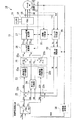
本実施の形態によるモータ制御装置10は、例えば図1に示すように、バッテリ11を直流電源とするパワードライブユニット(PDU)12と、制御部13とを備えて構成され、例えばモータMを駆動源として備えるハイブリッド車両や電動車両等の車両に搭載されている。
Hereinafter, an embodiment of a motor control device of the present invention will be described with reference to the accompanying drawings.
As shown in FIG. 1, for example, the
このモータ制御装置10において、モータMの駆動および回生作動は制御部13から出力される制御指令を受けてパワードライブユニット(PDU)12により行われる。
PDU12は、例えばトランジスタのスイッチング素子を複数用いてブリッジ接続してなるブリッジ回路を具備するパルス幅変調(PWM)によるPWMインバータを備え、各モータMと電気エネルギーの授受を行う高圧系のバッテリ11が接続されている。
PDU12は、例えばモータ制御装置10の駆動時等において制御部13から入力されるスイッチング指令であるゲート信号(つまり、PWM信号)に基づき、PWMインバータにおいて各相毎に対をなす各トランジスタのオン(導通)/オフ(遮断)状態を切り替えることによって、バッテリ11から供給される直流電力を3相交流電力に変換し、3相の固定子巻線への通電を順次転流させることで、各相の固定子巻線に交流のU相電流IuおよびV相電流IvおよびW相電流Iwを通電する。
In the
The
The
制御部13は、回転直交座標をなすdq座標上で電流のフィードバック制御を行うものであり、例えば運転者のアクセル操作に係るアクセル開度等に応じて設定されるトルク指令Tqcから目標d軸電流Idcおよび目標q軸電流Iqcを演算し、目標d軸電流Idc及び目標q軸電流Iqcに基づいて3相の各相出力電圧Vu,Vv,Vwを算出し、各相出力電圧Vu,Vv,Vwに応じてPDU12へゲート信号であるPWM信号を入力すると共に、実際にPDU12からモータ制御装置10に供給される各相電流Iu,Iv,Iwの検出値をdq座標上に変換して得たd軸電流Id及びq軸電流Iqと、目標d軸電流Idc及び目標q軸電流Iqcとの各偏差がゼロとなるように制御を行う。
The
例えばモータMの駆動時に、制御部13は、正弦波状の各相出力電圧Vu,Vv,Vwと、後述する同期制御部31の制御に応じた周波数および位相を有する三角波等のキャリア信号とに基づくパルス幅変調により、PWMインバータの各スイッチング素子をオン/オフ駆動させる各パルスからなるスイッチング指令であるゲート信号(つまり、パルス幅変調信号)を生成する。そして、PWMインバータにおいて3相の各相毎に対をなす各トランジスタのオン(導通)/オフ(遮断)状態を切り替えることによって、バッテリ11から供給される直流電力を3相交流電力に変換し、3相のモータMの各固定子巻線への通電を順次転流させることで、各固定子巻線12aに交流のU相電流IuおよびV相電流IvおよびW相電流Iwを通電する。
なお、各トランジスタUH,ULおよびVH,VLおよびWH,WLを、パルス幅変調(PWM)によりオン/オフ駆動させるためのパルスのデューティ、つまりオン/オフの比率のマップ(データ)は予め制御部13に記憶されている。
For example, when the motor M is driven, the
It should be noted that a map (data) of the pulse duty for turning on / off the transistors UH, UL and VH, VL and WH, WL by pulse width modulation (PWM); 13 is stored.
このため、制御部13には、PDU12からモータMの各相の固定子巻線毎に供給される各相電流Iu,Iv,Iwの少なくとも何れか2つ(例えば、U相電流Iu,W相電流Iw等)を検出する電流センサ14から出力される検出信号(例えば、U相検出電流Ius,W相検出電流Iws等)と、例えば座標変換の処理等において用いられるモータMのロータの回転角θm(つまり、所定の基準回転位置からのロータの磁極の回転角度であって、モータMの回転軸の回転位置)を検出する位置センサ15から出力される検出信号と、バッテリ11の端子電圧(電源電圧)を検出する電圧センサ(図示略)から出力される検出信号とが入力されている。
For this reason, the
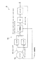
なお、位置センサ15は、例えば図2に示すように、レゾルバ15aおよびR/D(レゾルバ/デジタル)変換器15bを備えて構成され、レゾルバ15aに励磁回路(図示略)から励磁電圧Esinωtが供給され、レゾルバ15aから出力される回転角度θに応じた2つの出力信号(K・Esinωt・sinθおよびK・Esinωt・cosθ)がR/D変換器15bに入力されている。R/D変換器15bでは、一方の出力信号(K・Esinωt・sinθ)に(cosΦ)が乗算されて得られた値と、他方の出力信号(K・Esinωt・cosθ)に(sinΦ)が乗算されて得られた値との差((K・Esinωt・sin(θ−Φ))が同期整流回路に入力され、この同期整流回路での励磁電圧Esinωtに応じた同期整流を介して出力される信号(K・E・sin(θ−Φ))が電圧可変発振器(VCO)に入力され、この電圧可変発振器から出力される信号がカウンタに入力され、このカウンタから絶対電気角度として出力カウンタ値Φが出力されている。そして、θ=φとなるようにフィードバック制御が実行されている。
また、R/D(レゾルバ/デジタル)変換器15bは、原点相であるZ相のパルス列を出力している。
For example, as shown in FIG. 2, the
The R / D (resolver / digital)
制御部13は、電流のフィードバック制御を、後述するPWM信号生成部27でのパルス幅変調の処理で用いられるキャリア信号の周期と同等の制御周期で実行しており、このキャリア信号の周期と同等のサンプリング周期によって各相電流Iu,Iv,Iwの検出値を取得している。
そして、制御部13は、電流のフィードバック制御の一連の制御処理を繰り返し実行している際に、この制御周期をモータMの回転周期に同期させる同期制御を実行する。
The
And the
この制御部13は、例えば、目標電流設定部21と、電流偏差算出部22と、電流制御部23と、非干渉制御器24と、電圧補正部25と、dq−3相変換部26と、PWM信号生成部27と、フィルタ処理部28と、3相−dq変換29と、回転数演算部30と、同期制御部31とを備えて構成されている。
The
目標電流設定部21は、トルク指令Tqc(例えば、運転者によるアクセルペダルの踏み込み操作量に応じて必要とされるトルクをモータMに発生させるための指令値)と、回転数演算部30から入力されるモータMの回転数NMとに基づき、PDU12からモータMに供給される各相電流Iu,Iv,Iwを指定するための電流指令を演算しており、この電流指令は、回転する直交座標上でのd軸目標電流Idc及びq軸目標電流Iqcとして電流偏差算出部22へ出力されている。
The target
この回転直交座標をなすdq座標は、例えばロータの永久磁石による界磁極の磁束方向をd軸(界磁軸)とし、このd軸と直交する方向をq軸(トルク軸)としており、ロータの回転位相に同期して回転している。これにより、PDU12からモータMの各相に供給される交流信号に対する電流指令として、直流的な信号であるd軸目標電流Idcおよびq軸目標電流Iqcを与えるようになっている。
The dq coordinates forming the rotation orthogonal coordinates are, for example, a field magnetic flux direction of a rotor permanent magnet as a d axis (field axis) and a direction orthogonal to the d axis as a q axis (torque axis). It rotates in synchronization with the rotation phase. As a result, the d-axis target current Idc and the q-axis target current Iqc, which are DC signals, are given as current commands for the AC signal supplied from the
電流偏差算出部22は、d軸目標電流Idcとd軸電流Idとの偏差ΔIdを算出するd軸電流偏差算出部22aと、q軸目標電流Iqcとq軸電流Iqとの偏差ΔIqを算出するq軸電流偏差算出部22bとを備えて構成されている。
The current
電流制御部23は、例えばPI(比例積分)動作により、偏差ΔIdを制御増幅してd軸電圧指令値ΔVdを算出するd軸電流PI制御器23aと、偏差ΔIqを制御増幅してq軸電圧指令値Vqを算出するq軸電流PI制御器23bとを備えて構成されている。
The
また、非干渉制御器24は、例えばd軸目標電流Idcおよびq軸目標電流Iqcと、予め記憶されているd軸インダクタンスLdおよびq軸インダクタンスLqとに基づき、d軸とq軸との間で干渉し合う速度起電力成分を相殺してd軸及びq軸を独立して制御するために、d軸及びq軸に対する各干渉成分を相殺するd軸補償項Vdc及びq軸補償項Vqcを算出する。
Further, the
電圧補正部25は、d軸電圧指令値ΔVdとd軸補償項Vdcとを加算して得た値をd軸電圧指令値Vdとするd軸電圧加算部25aと、q軸電圧指令値ΔVqとq軸補償項Vqcとを加算して得た値をq軸電圧指令値Vqとするq軸電圧加算部25bとを備えて構成されている。
The
dq−3相変換部26は、位置センサ15から入力されるモータMの回転位置に相当する回転角θmにより、dq座標上でのd軸電圧指令値Vdおよびq軸電圧指令値Vqを、静止座標である3相交流座標上での電圧指令値であるU相出力電圧VuおよびV相出力電圧VvおよびW相出力電圧Vwに変換する。
The dq-3
PWM信号生成部27は、例えば、正弦波状の各相出力電圧Vu,Vv,Vwと、三角波からなるキャリア信号とに基づくパルス幅変調により、PDU12のPWMインバータの各スイッチング素子をオン/オフ駆動させる各パルスからなるスイッチング指令であるゲート信号(つまり、PWM信号)を生成する。
The PWM
フィルタ処理部28は、各電流センサ14,14により検出された各相電流に対する検出信号Ius,Iwsに対して、高周波成分の除去等のフィルタ処理を行い、後述する同期制御部31の制御に応じた物理量としての各相電流Iu,Iwを抽出する。
The
3相−dq変換29は、フィルタ処理部28により抽出された各相電流Iu,Iwと、位置センサ15から入力されるモータMの回転位置に相当する回転角θmとにより、モータMの回転位相による回転座標すなわちdq座標上でのd軸電流Idおよびq軸電流Iqを算出する。
The three-phase-
回転数演算部30は、位置センサ15から出力される検出信号からモータMの回転数NMを算出する。
The rotation
同期制御部31は、電流のフィードバック制御の一連の制御処理を繰り返し実行している際に、位置センサ15から出力される原点相であるZ相のパルス、つまりモータMの回転に同期して電気角での360°(edeg)周期で出力されるパルスと、予めモータMの回転数に応じて設定された所定の逓倍数および電流のフィードバック制御の制御周期に基づく割り込みカウンタとの位相差を検知し、モータMの回転周波数(つまり、回転数と極対数との積)が所定周波数以上かつ位相差が所定値以下である場合に、同期制御を実行する。
同期制御部31は、予めモータMの回転数に応じて設定された所定の逓倍数Nのデータを記憶すると共に、キャリア信号の周期毎にカウンタ値が初期化される加算型の割り込みカウンタを備え、例えば図3に示すように、位置センサ15から出力されるZ相のパルスと割り込みカウンタのカウンタ値がゼロとなるタイミングとの位相差Δtと、逓倍数Nと、1以下かつゼロよりも大きい所定係数kと、位置センサ15から出力されるZ相のパルスに応じたモータMの回転周期の電気角での1周期Tとに基づき、例えば下記数式(7)によって、キャリア信号の周期(つまり、割り込みカウンタの周期)Tcを設定する。
The
The
例えばモータMの速度変動が無視できる状態において、任意の自然数nによる時系列上で隣り合う位相差Δt(n)および位相差Δt(n+1)は、例えば下記数式(8)に示すように記述されることから、所定係数kを1とした場合には、上記数式(7)に応じてキャリア信号の周期Tcを設定する次回の処理において位相差Δtはゼロとなる。
また、例えば所定係数kを1未満かつゼロよりも大きい値とした場合には、上記数式(7)に応じてキャリア信号の周期Tcを繰り返し設定することによって、位相差Δtはゼロに収束することになる。
For example, in a state where the speed fluctuation of the motor M can be ignored, the phase difference Δt (n) and the phase difference Δt (n + 1) adjacent on the time series by an arbitrary natural number n are expressed by, for example, the following formula (8). As described above, when the predetermined coefficient k is 1, the phase difference Δt is zero in the next processing for setting the carrier signal cycle Tc according to the equation (7).
For example, when the predetermined coefficient k is set to a value less than 1 and greater than zero, the phase difference Δt converges to zero by repeatedly setting the cycle Tc of the carrier signal according to the equation (7). become.
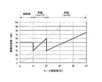
予めモータMの回転数に応じて設定された所定の逓倍数Nは、例えばモータMの回転周波数(モータ周波数)が所定上限周期以上で増大することに伴い、所定下限値に向かい減少傾向に変化するように設定されており、例えば図4に示す一例では、モータ周波数が所定値1f未満においては、同期制御は実行されず、電流のフィードバック制御の制御周波数、つまりキャリア信号の周波数は所定値5eに維持される。
そして、モータ周波数が所定値1f以上かつ所定値2f(>1f)未満においては、同期制御が実行され、逓倍数N=12とされ、電流のフィードバック制御の制御周波数、つまりキャリア信号の周波数は、上記数式(7)に応じて変化する。
そして、モータ周波数が所定値2f(>1f)以上に増大すると、同期制御の実行は維持されつつ、逓倍数Nは減少して、逓倍数N=6とされ、電流のフィードバック制御の制御周波数、つまりキャリア信号の周波数は、上記数式(7)に応じて変化する。
The predetermined multiplication number N set in advance according to the rotational speed of the motor M changes in a decreasing tendency toward the predetermined lower limit value, for example, as the rotational frequency (motor frequency) of the motor M increases at a predetermined upper limit period or more. For example, in the example shown in FIG. 4, when the motor frequency is less than the predetermined value 1f, the synchronous control is not executed, and the control frequency of the current feedback control, that is, the frequency of the carrier signal is the predetermined value 5e. Maintained.
When the motor frequency is equal to or higher than the predetermined value 1f and lower than the
When the motor frequency increases to a
つまり、同期制御部31は、モータMの回転数に応じて設定された所定の各逓倍数N毎に、制御周波数に対する所定の上限周波数および下限周波数(あるいは、制御周期に対する所定の下限周期および上限周期)を設定しており、同期制御の実行時において、制御周波数が所定の上限周波数よりも大きくなる(あるいは、制御周期が所定の下限周期未満になる)と共に逓倍数Nが所定下限値以上であると、逓倍数Nを減少させ、制御周波数が所定の下限周波数以下になる(あるいは、制御周期が所定の上限周期以上になる)と、逓倍数Nを増大させる。
That is, the
なお、同期制御部31は、同期制御の実行時において、上記数式(7)に応じて電流のフィードバック制御の制御周波数、つまりキャリア信号の周波数が、モータ周波数の増大に伴って増大する場合であっても、例えばPDU12のスイッチング素子等の各種の素子や制御装置等に対する所定の応答限界を超えないようにして、逓倍数Nを設定している。
The
また、同期制御部31は、電流のフィードバック制御の制御周期が所定下限周期未満、かつ、モータMの回転数に応じた逓倍数Nが所定下限値未満である場合には、同期制御の実行を禁止する。
The
そして、同期制御部31は、同期制御の実行時に、フィルタ処理部28において、モータMの回転周期に係る所定周期(例えば、電気角での360°(edeg)周期)に亘って各電流センサ14,14により検出された各相電流に対する検出信号Ius,Iwsに基づき、物理量としての各相電流Iu,Iwの所定周期(例えば、電気角での360°(edeg)周期)に亘る各平均値を抽出させる。そして、これらの各平均値によって電流のフィードバック制御が行われるように設定する。
Then, the
本実施形態によるモータ制御装置10は上記構成を備えており、次に、このモータ制御装置10の動作について添付図面を参照しながら説明する。
The
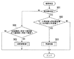
以下に、同期制御の実行要否を判定する制御判定の処理について説明する。
先ず、例えば図5に示すステップS01においては、電流のフィードバック制御の制御周波数が適宜の値に維持される同期制御の非実行状態であるか否かを判定する。
この判定結果が「NO」の場合には、後述するステップS04に進む。
一方、この判定結果が「YES」の場合には、ステップS02に進む。
そして、ステップS02においては、位置センサ15から出力される検出信号に基づき検知されるモータ周波数が所定周波数以上、かつ、位相差が所定値以下であるか否かを判定する。
この判定結果が「NO」の場合には、一連の処理を終了する。
一方、この判定結果が「YES」の場合には、ステップS03に進み、このステップS03においては、同期制御の実行を開始し、一連の処理を終了する。
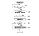
In the following, the control determination process for determining whether or not to execute the synchronous control will be described.
First, for example, in step S01 shown in FIG. 5, it is determined whether or not a synchronous control non-execution state in which the control frequency of the current feedback control is maintained at an appropriate value is determined.
If this determination is “NO”, the flow proceeds to step
On the other hand, if this determination is “YES”, the flow proceeds to step S 02.
In step S02, it is determined whether the motor frequency detected based on the detection signal output from the
When the determination result is “NO”, the series of processes is terminated.
On the other hand, if this determination is “YES”, the flow proceeds to step S 03, where synchronous control execution is started and the series of processing is terminated.
また、ステップS04においては、電流のフィードバック制御の制御周期が所定下限周期未満、かつ、モータMの回転数に応じた逓倍数が所定下限値未満であるか否かを判定する。
この判定結果が「NO」の場合には、一連の処理を終了する。
一方、この判定結果が「YES」の場合には、ステップS05に進み、このステップS05においては、同期制御の非実行状態として、一連の処理を終了する。
In step S04, it is determined whether or not the control period of the current feedback control is less than a predetermined lower limit period, and the multiplication number corresponding to the rotation speed of the motor M is less than the predetermined lower limit value.
When the determination result is “NO”, the series of processes is terminated.
On the other hand, if this determination is “YES”, the flow proceeds to step
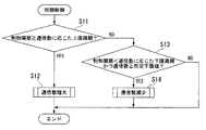
以下に、上述したステップS03の同期制御において、逓倍数を設定する処理について説明する。
先ず、例えば図6に示すステップS11においては、電流のフィードバック制御の制御周期が、この時点での逓倍数に応じて予め設定された所定の上限周期以上であるか否かを判定する。
この判定結果が「NO」の場合には、後述するステップS13に進む。
一方、この判定結果が「YES」の場合には、ステップS12に進む。
そして、ステップS12においては、例えばモータ周波数および制御周波数に応じて予め設定された逓倍数のマップ等を参照して、逓倍数を増大させ、一連の処理を終了する。
Below, the process which sets the multiplication number in the synchronous control of step S03 mentioned above is demonstrated.
First, for example, in step S11 shown in FIG. 6, it is determined whether or not the control period of the current feedback control is equal to or greater than a predetermined upper limit period preset according to the multiplication number at this time.
If this determination is “NO”, the flow proceeds to step
On the other hand, if this determination is “YES”, the flow proceeds to step S12.
In step S12, for example, referring to a map of multiplication numbers set in advance according to the motor frequency and the control frequency, the multiplication number is increased, and the series of processing ends.
また、ステップS13においては、電流のフィードバック制御の制御周期が、この時点での逓倍数に応じて予め設定された所定の下限周期未満、かつ、この時点での制御周期およびモータ周波数に応じた逓倍数が所定下限値以上であるか否かを判定する。
この判定結果が「NO」の場合には、一連の処理を終了する。
一方、この判定結果が「YES」の場合には、例えばモータ周波数および制御周波数に応じて予め設定された逓倍数のマップ等を参照して、逓倍数を減少させ、一連の処理を終了する。
Further, in step S13, the control period of the current feedback control is less than a predetermined lower limit period preset according to the multiplication number at this time, and the multiplication according to the control period and the motor frequency at this time. It is determined whether the number is equal to or greater than a predetermined lower limit value.
When the determination result is “NO”, the series of processes is terminated.
On the other hand, when the determination result is “YES”, for example, referring to a map of multiplication numbers set in advance according to the motor frequency and the control frequency, the multiplication number is decreased, and the series of processes is ended.
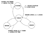
なお、図7には、同期制御と非同期制御との状態間の遷移条件、および、同期制御での逓倍数の増大処理および逓倍数の減少処理に対する各遷移条件の一例を示した。 FIG. 7 shows an example of the transition condition between the states of the synchronous control and the asynchronous control, and each transition condition for the multiplication number increase process and the multiplication number decrease process in the synchronous control.
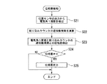
以下に、同期制御の実行時において位相差を検知する処理について説明する。
先ず、例えば図8に示すステップS21においては、位置センサ15から出力されるZ相のパルスに基づき、モータMの回転周期の電気角での1周期を検出する。
次に、ステップS22においては、モータMの回転数に応じて設定された所定の逓倍数を取得し、割り込みカウンタの周期(つまり、キャリア信号の周期)に逓倍数を乗算して逓倍数周期を演算する。
次に、ステップS23においては、モータMの回転周期の電気角での1周期と、割り込みカウンタの逓倍数周期との位相差を検出する。
そして、ステップS24においては、位相差がゼロ以外であるか否かを判定する。
この判定結果が「NO」の場合には、一連の処理を終了する。
一方、この判定結果が「YES」の場合には、ステップS25に進み、このステップS25においては、位相差のデータを出力する。
Below, the process which detects a phase difference at the time of execution of synchronous control is demonstrated.
First, for example, in step S21 shown in FIG. 8, one cycle at the electrical angle of the rotation cycle of the motor M is detected based on the Z-phase pulse output from the
Next, in step S22, a predetermined multiplication number set in accordance with the number of rotations of the motor M is obtained, and the multiplication counter period is obtained by multiplying the interruption counter period (that is, the carrier signal period) by the multiplication number. Calculate.
Next, in step S23, a phase difference between one cycle in the electrical angle of the rotation cycle of the motor M and a multiplication cycle of the interrupt counter is detected.
In step S24, it is determined whether or not the phase difference is other than zero.
When the determination result is “NO”, the series of processes is terminated.
On the other hand, if this determination is “YES”, the flow proceeds to step
以下に、同期制御の実行時において、電流のフィードバック制御の一連の制御処理をキャリア信号の周期と同等の制御周期毎に繰り返し実行する処理である制御割り込みの処理について説明する。
先ず、例えば図9に示すステップS31においては、割り込みカウンタのカウンタ値が所定の上限値に到達することでカウンタ値が初期化されるタイミング、つまり制御割り込みのタイミングであるか否かを判定する。
この判定結果が「NO」の場合には、このステップS31の判定処理を繰り返す。
一方、この判定結果が「YES」の場合には、ステップS32に進む。
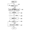
In the following, a control interrupt process, which is a process of repeatedly executing a series of control processes of current feedback control for each control period equivalent to the period of the carrier signal when executing synchronous control, will be described.
First, for example, in step S31 shown in FIG. 9, it is determined whether or not it is the timing at which the counter value is initialized when the counter value reaches the predetermined upper limit value, that is, the control interrupt timing.
If the determination result is “NO”, the determination process of step S31 is repeated.
On the other hand, if this determination is “YES”, the flow proceeds to step S32.
そして、ステップS32においては、各電流センサ14,14により検出された各相電流に対する検出信号Ius,Iws、および、上述したステップS21〜ステップS25にて検知された位相差等の各種の制御量のデータを取得する。
そして、ステップS33においては、モータMの回転周期に係る所定周期(例えば、電気角での360°(edeg)周期)に亘って取得された各検出信号Ius,Iwsに基づく、各相電流Iu,Iwの所定周期(例えば、電気角での360°(edeg)周期)に亘る各平均値によって、電流のフィードバック制御を実行する。
In step S32, the detection signals Ius and Iws for the phase currents detected by the current sensors 14 and 14 and various control amounts such as the phase differences detected in steps S21 to S25 described above. Get the data.
In step S33, each phase current Iu, based on each detection signal Ius, Iws acquired over a predetermined period (for example, 360 ° (edeg) period in electrical angle) related to the rotation period of the motor M. Current feedback control is executed by each average value over a predetermined cycle of Iw (for example, 360 ° (edeg) cycle in electrical angle).
そして、ステップS34においては、電流のフィードバック制御における制御指令、つまり静止座標である3相交流座標上での電圧指令値であるU相出力電圧VuおよびV相出力電圧VvおよびW相出力電圧Vwを出力する。
そして、ステップS35においては、取得した位相差がゼロ以外であるか否かを判定する。
この判定結果が「NO」の場合には、一連の処理を終了する。
一方、この判定結果が「YES」の場合には、ステップS36に進み、このステップS36においては、割り込みカウンタのカウンタ値を初期化すると共に、割り込みカウンタの周期(つまり、キャリア信号の周期)を、例えば上記数式(7)によって新たに設定し、一連の処理を終了する。
In step S34, the control command in the current feedback control, that is, the U-phase output voltage Vu, the V-phase output voltage Vv, and the W-phase output voltage Vw, which are voltage command values on the three-phase AC coordinates that are stationary coordinates, are obtained. Output.
In step S35, it is determined whether or not the acquired phase difference is other than zero.
When the determination result is “NO”, the series of processes is terminated.
On the other hand, if this determination result is "YES", the process proceeds to step S36, where the counter value of the interrupt counter is initialized and the period of the interrupt counter (that is, the period of the carrier signal) is For example, a new setting is made by the above equation (7), and the series of processing ends.
上述したように、本実施の形態によるモータ制御装置10によれば、キャリア信号の周期に応じた制御周期(例えば、キャリア信号の周期と同等の制御周期)によって、モータMの電流のフィードバック制御を実行する際に、この制御周期をモータMの回転周期に同期させることができ、検出系の誤差に起因してモータ制御の安定性が低下しまうことを抑制することができる。しかも、キャリア信号の周波数を、モータMの回転周期の電気角での1周期あたりで所定の逓倍数となるように設定することで、モータMの回転周波数の増大に伴い、キャリア信号の周波数が過剰に増大することを防止することができ、モータMの誘起電圧およびモータMの各相電流に含まれる高調波成分に起因してモータ制御の安定性が低下しまうことを抑制することができる。これにより、モータMを小型化しつつ出力を適切に増大させることができる。
また、モータMの回転周波数が所定周波数以上かつ位相差が所定値以下である場合に制御周期をモータMの回転周期に同期させることから、モータMの回転周波数が所定周波数未満である場合に、制御周期をモータの回転周期に同期させる処理が過剰に実行されてしまうことを防止することができると共に、位相差の初期値が所定値よりも大きい場合に、制御周期をモータMの回転周期に同期させることが困難となってしまうことを防止することができる。
As described above, according to the
Further, when the rotational frequency of the motor M is equal to or higher than the predetermined frequency and the phase difference is equal to or lower than the predetermined value, the control cycle is synchronized with the rotational cycle of the motor M. It is possible to prevent the process of synchronizing the control period with the rotation period of the motor from being excessively executed, and when the initial value of the phase difference is larger than a predetermined value, the control period is set to the rotation period of the motor M. It can be prevented that it is difficult to synchronize.
さらに、同期制御の実行時においては、モータMの回転周期に係る所定周期(例えば、電気角での360°(edeg)周期)に亘って取得された各検出信号Ius,Iwsに基づく、各相電流Iu,Iwの所定周期(例えば、電気角での360°(edeg)周期)に亘る各平均値によって、電流のフィードバック制御を実行することにより、各電流センサ14,14の検出誤差に起因して制御系の安定性が低下してしまうことを防止することができる。
さらに、上記数式(7)において、1以下かつゼロよりも大きい所定係数kに基づき、キャリア信号の周期Tcを設定することから、例えばモータMの回転速度が変動する場合には、所定係数kを1未満とすることで、位相差Δtをゼロに収束させる際の制御ゲインを適切に設定することができ、位相差Δtに振動等が発生してしまうことを防止することができる。
Furthermore, at the time of execution of synchronous control, each phase based on each detection signal Ius, Iws acquired over a predetermined period (for example, 360 ° (edeg) period in electrical angle) related to the rotation period of the motor M. Due to the detection error of each of the current sensors 14 and 14 by executing feedback control of the current according to each average value over a predetermined period (for example, 360 ° (edeg) period in electrical angle) of the currents Iu and Iw. Thus, it is possible to prevent the stability of the control system from being lowered.
Further, in the above formula (7), since the cycle Tc of the carrier signal is set based on a predetermined coefficient k that is equal to or less than 1 and greater than zero, for example, when the rotational speed of the motor M varies, the predetermined coefficient k is set to By setting it to less than 1, it is possible to appropriately set the control gain when the phase difference Δt converges to zero, and it is possible to prevent the occurrence of vibration or the like in the phase difference Δt.
以下に、上述した実施の形態によるモータ制御装置10によって電流のフィードバック制御を実行した試験結果について説明する。
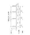
この試験においては、モータMの回転周波数を増大させることに相当する処理として、キャリア信号の周波数を低下させ、この状態で電流のフィードバック制御の制御周期と、モータMの回転周期との位相差がゼロとなるように同期制御を実行した。
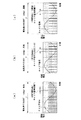
先ず、10極のモータMの回転数を3000rpmとし、通電電流を30Armsとして、モータMの回転周波数が相対的に低い状態に対応する非同期制御の状態では、例えば図10(a),図11(a)に示すように、キャリア信号の周波数(つまり、割り込みカウンタの周波数)は10KHzに維持され、各相電流(U,V,W相電流)の電流振幅はほぼ同等の値となっている。
そして、モータMの回転周波数が相対的に高い状態に変化した場合に対応して、キャリア信号の周波数を10kHzから6kHzに低下させると、キャリア信号の周期は適宜の周期T1から周期T2(>T1)へと変化し、例えば図10(b),図11(b)に示すように、キャリア信号の周期つまり割り込みカウンタのカウンタ値がゼロになるタイミングと、モータMの回転周期との位相差に起因して、各相電流(U,V,W相電流)の電流振幅のばらつきが増大し、電流のフィードバック制御が不安定となる。
ここで、同期制御を実行し、モータMの回転周期に係る所定周期(例えば、電気角での360°(edeg)周期)において逓倍数を12とした状態(つまり、12個のキャリア信号が含まれる状態)で、キャリア信号の周期つまり割り込みカウンタのカウンタ値がゼロになるタイミングと、モータMの回転周期との位相差をゼロとすることにより、例えば図10(c),図11(c)に示すように、各相電流(U,V,W相電流)の電流振幅はほぼ同等の値となり、電流のフィードバック制御を安定化させることができる。
Below, the test result which performed the feedback control of the electric current by the
In this test, as a process corresponding to increasing the rotation frequency of the motor M, the frequency of the carrier signal is decreased, and in this state, the phase difference between the control period of the current feedback control and the rotation period of the motor M is Synchronous control was executed so that it would be zero.
First, in the asynchronous control state corresponding to the state where the rotational frequency of the motor M is set to 3000 rpm, the energization current is set to 30 Arms, and the rotational frequency of the motor M is relatively low, for example, FIG. As shown in a), the frequency of the carrier signal (that is, the frequency of the interrupt counter) is maintained at 10 KHz, and the current amplitude of each phase current (U, V, W phase current) is almost the same value.
Then, when the frequency of the carrier signal is decreased from 10 kHz to 6 kHz corresponding to the case where the rotational frequency of the motor M is changed to a relatively high state, the period of the carrier signal is changed from an appropriate period T1 to a period T2 (> T1). For example, as shown in FIGS. 10B and 11B, the phase difference between the carrier signal cycle, that is, the timing at which the counter value of the interrupt counter becomes zero, and the rotation cycle of the motor M is changed. As a result, the variation in the current amplitude of each phase current (U, V, W phase current) increases, and the current feedback control becomes unstable.
Here, the synchronous control is executed, and a state where the multiplication number is 12 in a predetermined cycle (for example, 360 ° (edeg) cycle in electrical angle) related to the rotation cycle of the motor M (that is, 12 carrier signals are included). 10 (c) and FIG. 11 (c), for example, by setting the phase difference between the carrier signal cycle, that is, the timing at which the counter value of the interrupt counter becomes zero, and the rotation cycle of the motor M to zero. As shown in FIG. 5, the current amplitude of each phase current (U, V, W phase current) becomes substantially the same value, and the current feedback control can be stabilized.
なお、上述した実施の形態では、制御割り込みの処理において、上述したステップS21〜ステップS25にて検知された位相差を取得するとしたが、これに限定されず、例えば制御割り込みの処理において位相差を検知してもよい。
この変形例に係る制御割り込みの処理では、例えば図12に示すように、先ず、ステップS41において、割り込みカウンタのカウンタ値が所定の上限値に到達することでカウンタ値が初期化されるタイミング、つまり制御割り込みのタイミングであるか否かを判定する。
この判定結果が「NO」の場合には、このステップS41の判定処理を繰り返す。
一方、この判定結果が「YES」の場合には、ステップS42に進む。
In the above-described embodiment, the phase difference detected in steps S21 to S25 described above is acquired in the control interrupt processing. However, the present invention is not limited to this. For example, the phase difference is determined in the control interrupt processing. It may be detected.
In the control interrupt processing according to this modification, for example, as shown in FIG. 12, first, in step S41, the timing at which the counter value is initialized when the counter value of the interrupt counter reaches a predetermined upper limit value, that is, It is determined whether it is the timing of the control interrupt.
If the determination result is “NO”, the determination process of step S41 is repeated.
On the other hand, if this determination is “YES”, the flow proceeds to step S42.
そして、ステップS42においては、各電流センサ14,14により検出された各相電流に対する検出信号Ius,Iws、および、位置センサ15から出力される検出信号等の各種の制御量のデータを取得する。
そして、ステップS43においては、位置センサ15から出力される検出信号に基づき、例えばモータMの回転角θmと所定の原点位置との位相差を検知する。
そして、ステップS44においては、モータMの回転周期に係る所定周期(例えば、電気角での360°(edeg)周期)に亘って取得された各検出信号Ius,Iwsに基づく、各相電流Iu,Iwの所定周期(例えば、電気角での360°(edeg)周期)に亘る各平均値によって、電流のフィードバック制御を実行する。
In step S42, data of various control amounts such as detection signals Ius and Iws for each phase current detected by the current sensors 14 and 14 and a detection signal output from the
In step S43, based on the detection signal output from the
In step S44, each phase current Iu, based on each detection signal Ius, Iws acquired over a predetermined period (eg, 360 ° (edeg) period in electrical angle) related to the rotation period of the motor M. Current feedback control is executed by each average value over a predetermined cycle of Iw (for example, 360 ° (edeg) cycle in electrical angle).
そして、ステップS45においては、電流のフィードバック制御における制御指令、つまり静止座標である3相交流座標上での電圧指令値であるU相出力電圧VuおよびV相出力電圧VvおよびW相出力電圧Vwを出力する。
そして、ステップS46においては、検知した位相差がゼロ以外であるか否かを判定する。
この判定結果が「NO」の場合には、一連の処理を終了する。
一方、この判定結果が「YES」の場合には、ステップS47に進み、このステップS47においては、割り込みカウンタのカウンタ値を初期化すると共に、割り込みカウンタの周期(つまり、キャリア信号の周期)を、例えば上記数式(7)によって新たに設定し、一連の処理を終了する。
In step S45, the control command in the current feedback control, that is, the U-phase output voltage Vu, the V-phase output voltage Vv, and the W-phase output voltage Vw, which are voltage command values on the three-phase AC coordinates that are stationary coordinates, are obtained. Output.
In step S46, it is determined whether or not the detected phase difference is other than zero.
When the determination result is “NO”, the series of processes is terminated.
On the other hand, if this determination is “YES”, the flow proceeds to step S 47, in which the counter value of the interrupt counter is initialized, and the interrupt counter cycle (that is, the carrier signal cycle) is For example, a new setting is made by the above equation (7), and the series of processing ends.
なお、上述した実施の形態では、同期制御部31は位相差Δtをゼロに収束させるとしたが、これに限定されず、例えば位相差Δtを所定位相差に収束させてもよい。
In the above-described embodiment, the
なお、上述した実施の形態では、同期制御部31は位置センサ15から出力されるパルスに基づきモータMの回転周期を検出するとしたが、これに限定されず、モータMの回転周期に同期した信号に基づきモータMの回転周期を検出すればよく、例えば駆動源としてのモータMおよび内燃機関が直列に直結されたハイブリッド車両等においては、内燃機関に具備されて相対的に高精度の信号を出力可能なパルスセンサ等の各種のセンサから出力されるパルスに基づき、モータMの回転周期を検出してもよい。
In the above-described embodiment, the
なお、上述した実施の形態では、同期制御部31はモータMの回転位置に相当する回転角に係る角速度が変動する場合に、モータMの回転周期を予測し、この予測回転周期に基づき、同期制御を実行してもよい。
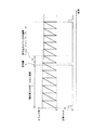
例えばモータMの回転状態が等角加速度回転である場合には、図13に示すように、位置センサ15から出力されるZ相のパルスの時系列上で隣り合うパルス同士間の間隔(パルス間隔Tw(m),(mは任意の正の整数)は、増大する角速度(角速度ω0,ω1,ω2,ω3,…)に反比例して短縮される。
例えばパルス間隔Tw(0)は、角速度ωと、回転角θと、時間tと、所定係数a,ω0とに基づく下記数式(9)から、解析的には、例えば下記数式(10)に示すように記述される。
In the above-described embodiment, the
For example, when the rotation state of the motor M is equiangular acceleration rotation, as shown in FIG. 13, an interval (pulse interval) between adjacent pulses in the time series of Z-phase pulses output from the
For example, the pulse interval Tw (0) is analytically expressed by, for example, the following formula (10) from the following formula (9) based on the angular velocity ω, the rotation angle θ, the time t, and the predetermined coefficients a and ω0. Is described as follows.
しかしながら、各パルス間隔Tw(m),(mは任意の正の整数)に対して解析解を演算する場合には演算負荷が過剰に増大することになる。
このため、同期制御部31は、例えば下記数式(11)に示すように、時系列上で隣り合うパルス同士間の間隔が不変である(つまり、差分ΔT(n)=0,(nは任意の自然数))と仮定して、モータMの予測回転周期を予測してもよい。
However, when an analytical solution is calculated for each pulse interval Tw (m), (m is an arbitrary positive integer), the calculation load increases excessively.
For this reason, as shown in the following formula (11), for example, the
また、同期制御部31は、例えば下記数式(12)に示すように、時系列上で隣り合うパルス同士間の間隔の変化量が所定変化量であると仮定して、モータMの予測回転周期を予測してもよい。
Further, the
また、同期制御部31は、例えば下記数式(13)に示すように、時系列上で隣り合うパルス同士間の間隔の変化量が所定比率kに応じて変化すると仮定して、モータMの予測回転周期を予測してもよい。
In addition, the
また、同期制御部31は、例えば下記数式(14)に示すように、時系列上で隣り合うパルス同士間の間隔が所定比率に応じて変化すると仮定して、モータMの予測回転周期を予測してもよい。
The
これらの変形例によれば、モータMの回転角度に係る角速度が変動するであっても、煩雑な解析処理を実行する必要無しに、精度の良い予測回転周期に基づき、同期制御を適切に実行することができる。 According to these modified examples, even if the angular velocity related to the rotation angle of the motor M fluctuates, the synchronous control is appropriately executed based on the accurate predicted rotation cycle without the need for performing complicated analysis processing. can do.
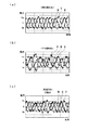
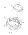
なお、上述した実施の形態では、モータMは、特に限定されず、例えば図13から図15に示すようにクローポール型モータ等であってもよい。
このクローポール型モータ50は、例えば複数の永久磁石51a,…,51aを有するロータ51と、このロータ51を回転させる回転磁界を発生する複数相(例えば、U相,V相,W相の3相)のステータ52とを備えて構成されている。
In the embodiment described above, the motor M is not particularly limited, and may be, for example, a claw pole type motor or the like as shown in FIGS.
The claw
このロータ51において、複数の略長方形板状の永久磁石51a,…,51aは、例えばロータ51の外周部に周方向に所定間隔をおいて配置され、各永久磁石51aは厚さ方向(つまりロータ51の径方向)に磁化され、周方向で隣り合う永久磁石51a,51aは互いに磁化方向が異方向となるように、すなわち外周側がN極とされた永久磁石51aには、外周側がS極とされた永久磁石51aが周方向で隣接するように配置されている。
また、各永久磁石51aの外周面は、ロータ51の外周部に対向配置される略円筒状のステータ52の内周面に向かい露出している。
In this
Further, the outer peripheral surface of each
ロータ51を回転させる回転磁界を発生するステータ52は、U相およびV相およびW相からなる3相の各相毎のU相ステータリング61と、V相ステータリング62と、W相ステータリング63と、U相およびW相からなる2相のU相環状巻線64およびW相環状巻線65とを備えて構成されている。
The
U相ステータリング61は、例えば図15に示すように、略円環状のU相ヨーク71と、このU相ヨーク71の内周部の周方向Cに所定間隔を置いた位置から径方向R内方および軸線方向Pの他方に向かい突出し、径方向Rに対する断面形状が略長方形状に形成されたU相ティース72とを備えて構成され、U相ヨーク71およびU相ティース72からなるU相ステータリング61の周方向Cに対する断面形状が略L字状となるように構成されている。
For example, as shown in FIG. 15, the
V相ステータリング62は、例えば図15に示すように、略円環状のV相ヨーク73と、このV相ヨーク73の内周部の周方向Cに所定間隔を置いた位置から径方向R内方および軸線方向Pの一方および他方に向かい突出し、径方向Rに対する断面形状が略長方形状に形成されたV相ティース74とを備えて構成され、V相ヨーク73およびV相ティース24からなるV相ステータリング62の周方向Cに対する断面形状が略T字状となるように構成されている。
For example, as shown in FIG. 15, the V-
W相ステータリング63は、例えば図15に示すように、略円環状のW相ヨーク75と、このW相ヨーク75の内周部の周方向Cに所定間隔を置いた位置から径方向R内方および軸線方向Pの一方に向かい突出し、径方向Rに対する断面形状が略長方形状に形成されたW相ティース76とを備えて構成され、W相ヨーク75およびW相ティース76からなるW相ステータリング63の周方向Cに対する断面形状が略L字状となるように構成されている。
For example, as shown in FIG. 15, the W-
そして、各ステータリング61,62,63は、各ヨーク71,73,75が軸線方向Pに沿って積み重ねられるようにして接続されている。そして、例えば図15に示すように、複数の各ティース72,…,72および74,…,74および76,…,76が所定順序(例えば、順次、U相ティース72,V相ティース74,W相ティース76等)で周方向Cに沿って配列され、周方向Cで隣り合う各ティース72,74間には1相のU相環状巻線64が配置されるスロットが形成され、周方向Cで隣り合う各ティース74,76間には1相のW相環状巻線65が配置されるスロットが形成され、周方向Cで隣り合う各ティース72,76間には2相のU相環状巻線64およびW相環状巻線65が配置されるスロットが形成されている。
The stator rings 61, 62, 63 are connected such that the
そして、各ステータリング61,62,63の各ティース72,74、76は、例えば互いに同等の軸方向幅および周方向幅を有し、周方向Cで隣り合う各ティース72,74,76間の間隔(つまり、各スロットの周方向幅)は、各スロットに配置される各環状巻線64,65の本数に応じた値(例えば、本数に比例した値等)に設定されている。つまり、単一の各環状巻線64,65が配置される各ティース72,74間および各ティース74,76間の間隔C1は、2相の各環状巻線64,65が配置される各ティース72,76間の間隔C2よりも小さな値(例えば、各ティース72,76間の間隔C2の1/2の値等)に設定されている。
And each
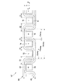
各環状巻線64,65は、例えば軸線周りの周面内でクランク状に蛇行しつつ周回するようにして、複数の各U相蛇行部81,…,81およびW相蛇行部82,…,82を備えて構成されている。
各蛇行部81,82の周方向Cの幅つまりコイルピッチは、例えば図14に示すように、電気角で120°に設定され、各蛇行部81,82は互いに異なる方向(つまり互いの対向方向であって軸線方向Pの一方および他方)に向かい突出するように設けられ、U相環状巻線64とW相環状巻線65とは、電気角で240°(edeg)の位相差を有するようにして周方向Cに沿って相対的にずれた位置に配置されている。これにより、例えばU相蛇行部81に対して、周方向Cの一方側で隣り合うW相蛇行部82は電気角で240°(edeg)の位相差を有し、周方向Cの他方側で隣り合うW相蛇行部82は電気角で120°(edeg)の位相差を有することになる。そして、2相の各環状巻線64,65は、互いの対向方向に突出する互いの各蛇行部81,82が周方向Cに沿って交互に配列され、互いに交差しないように配置されている。
Each of the
For example, as shown in FIG. 14, the width of each meandering
そして、U相環状巻線64のU相蛇行部81にはU相ステータリング61の1つのU相ティース72が配置され、W相環状巻線65のW相蛇行部82にはW相ステータリング63の1つのW相ティース76が配置され、周方向Cで隣り合うU相蛇行部81とW相蛇行部82との間にはV相ステータリング62の1つのV相ティース74が配置されている。
これにより、周方向Cで隣り合う各ティース72,74または74,76または72,76間を縫うようにして配置された2相の各環状巻線64,65は所謂電気角で120°(edeg)の短節波巻きをなすように形成されている。
One
Thus, the two-phase
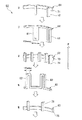
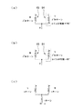
そして、互いに電気角で240°(edeg)の位相差(コイル位相差)を有する2相の各環状巻線64,65は、例えば図16(a)に示すように、V字状に結線され、互いに120°の位相差の正弦波で通電されることにより、例えば漏れ磁束が無視できる場合には、図16(c)に示すように、U相,V相,W相の3相巻線がY字状に結線され、互いに120°の位相差の正弦波で通電される3相のステータと同等の回転磁界を発生するように構成されている。
The two-phase
なお、例えば図16(b)に示すように、各蛇行部31,32が同等の方向(つまり軸線方向Pの一方または他方)に向かい突出する状態で互いに電気角で60°(edeg)の位相差を有する2相の各環状巻線64,65をV字状に結線する状態は、図16(a)に示すように、各蛇行部81,82が互いに異なる方向(つまり軸線方向Pの一方および他方)に向かい突出する状態で互いに電気角で240°(edeg)の位相差を有する2相の各環状巻線64,65をV字状に結線する状態と同様に、互いに120°の位相差の正弦波で通電された際に、例えば漏れ磁束が無視できる場合には、図16(c)に示すように、U相,V相,W相の3相巻線がY字状に結線され、互いに120°の位相差の正弦波で通電される3相のステータと同等の回転磁界を発生可能である。
For example, as shown in FIG. 16 (b), each meandering
10 モータ制御装置
12 PDU(インバータ)
14 電流センサ
15 位置センサ(回転状態量センサ、角度センサ)
27 PWM信号生成部(パルス幅変調信号生成手段)
31 同期制御部(位相差検知手段、周波数設定手段、同期手段、禁止手段、近似手段)
51 ロータ(回転子)
52 ステータ(固定子)
64 U相環状巻線(環状巻線)
65 W相環状巻線(環状巻線)
72 U相ティース(爪状誘導極)
74 V相ティース(爪状誘導極)
76 W相ティース(爪状誘導極)
ステップS04〜ステップS05 禁止手段
ステップS21〜ステップS23 位相差検知手段
ステップS33 電流制御手段
ステップS36 周波数設定手段、同期手段
10
14
27 PWM signal generator (pulse width modulation signal generator)
31 Synchronization control unit (phase difference detection means, frequency setting means, synchronization means, prohibition means, approximation means)
51 Rotor
52 Stator
64 U-phase annular winding (annular winding)
65 W-phase annular winding (annular winding)
72 U-phase teeth (nail-shaped induction pole)
74 V-phase teeth (nail-shaped induction pole)
76 W-phase teeth (nail-shaped induction pole)
Step S04 to Step S05 Inhibiting means Step S21 to Step S23 Phase difference detecting means Step S33 Current control means Step S36 Frequency setting means, synchronization means
Claims (12)
周波数および位相を変更可能なキャリア信号により前記パルス幅変調信号を生成するパルス幅変調信号生成手段と、
前記モータの回転周期に係る回転状態量を検出する回転状態量センサと、
前記回転状態量に基づき、前記キャリア信号と前記回転周期との位相差を検知する位相差検知手段と、
前記モータの回転周波数が所定周波数以上かつ前記位相差が所定値以下である場合に、前記モータの回転数に応じて変化する逓倍数に基づき、前記キャリア信号の周波数を、前記モータの回転周期の電気角での1周期あたりで前記逓倍数に応じた値に設定する周波数設定手段、および、前記キャリア信号に係る制御周期を前記モータの回転周期に同期させる同期手段と
を備えることを特徴とするモータ制御装置。 An inverter that sequentially commutates the energization of the motor with a pulse width modulation signal;
Pulse width modulation signal generating means for generating the pulse width modulation signal by a carrier signal whose frequency and phase can be changed; and
A rotational state quantity sensor for detecting a rotational state quantity relating to the rotational period of the motor;
Phase difference detection means for detecting a phase difference between the carrier signal and the rotation period based on the rotation state quantity;
When the rotational frequency of the motor is equal to or higher than a predetermined frequency and the phase difference is equal to or lower than a predetermined value, the frequency of the carrier signal is determined based on the multiplication number that changes according to the rotational speed of the motor. Frequency setting means for setting a value corresponding to the multiplication number per cycle in an electrical angle, and synchronization means for synchronizing a control cycle related to the carrier signal with a rotation cycle of the motor. Motor control device.
前記モータの回転周期に係る所定周期に亘って前記電流センサにより検出された電流検出値の平均値に基づき、前記モータの電流制御を実行する電流制御手段と
を備えることを特徴とする請求項1または請求項2に記載のモータ制御装置。 A current sensor capable of detecting an energization current of the motor according to the control period;
2. A current control unit that performs current control of the motor based on an average value of current detection values detected by the current sensor over a predetermined period related to the rotation period of the motor. Or the motor control apparatus of Claim 2.
前記回転角度に係る角速度が変動する場合に、時系列上で隣り合う前記パルス同士間の間隔が不変であると仮定して、前記モータの予測回転周期を予測し、前記予測回転周期を前記回転周期として設定する近似手段を備えることを特徴とする請求項1から請求項7の何れかひとつに記載のモータ制御装置。 The rotational state quantity sensor includes an angle sensor that outputs a pulse corresponding to a rotation angle of the motor,
When the angular velocity related to the rotation angle fluctuates, the predicted rotation period of the motor is predicted assuming that the interval between the adjacent pulses on the time series is unchanged, and the predicted rotation period is rotated. The motor control apparatus according to claim 1, further comprising an approximation unit that sets the period.
前記回転角度に係る角速度が変動する場合に、時系列上で隣り合う前記パルス同士間の間隔の変化量が所定変化量であると仮定して、前記モータの予測回転周期を予測し、前記予測回転周期を前記回転周期として設定する近似手段を備えることを特徴とする請求項1から請求項7の何れかひとつに記載のモータ制御装置。 The rotational state quantity sensor includes an angle sensor that outputs a pulse corresponding to a rotation angle of the motor,
When the angular velocity related to the rotation angle fluctuates, it is assumed that the change amount of the interval between the pulses adjacent in time series is a predetermined change amount, and predicts the predicted rotation period of the motor, and the prediction The motor control apparatus according to claim 1, further comprising an approximation unit that sets a rotation period as the rotation period.
前記回転角度に係る角速度が変動する場合に、時系列上で隣り合う前記パルス同士間の間隔の変化量が所定比率に応じて変化すると仮定して、前記モータの予測回転周期を予測し、前記予測回転周期を前記回転周期として設定する近似手段を備えることを特徴とする請求項1から請求項7の何れかひとつに記載のモータ制御装置。 The rotational state quantity sensor includes an angle sensor that outputs a pulse corresponding to a rotation angle of the motor,
When the angular velocity related to the rotation angle varies, assuming that the amount of change in the interval between the pulses adjacent in time series changes according to a predetermined ratio, predict the predicted rotation period of the motor, The motor control apparatus according to claim 1, further comprising an approximation unit that sets a predicted rotation period as the rotation period.
前記回転角度に係る角速度が変動する場合に、時系列上で隣り合う前記パルス同士間の間隔が所定比率に応じて変化すると仮定して、前記モータの予測回転周期を予測し、前記予測回転周期を前記回転周期として設定する近似手段を備えることを特徴とする請求項1から請求項7の何れかひとつに記載のモータ制御装置。 The rotational state quantity sensor includes an angle sensor that outputs a pulse corresponding to a rotation angle of the motor,
When the angular velocity related to the rotation angle fluctuates, the predicted rotation cycle of the motor is predicted assuming that the interval between the pulses adjacent in time series changes according to a predetermined ratio, and the predicted rotation cycle The motor control apparatus according to claim 1, further comprising an approximation unit that sets the rotation period as the rotation period.
Priority Applications (2)
| Application Number | Priority Date | Filing Date | Title |
|---|---|---|---|
| JP2007114047A JP4909797B2 (en) | 2007-04-24 | 2007-04-24 | Motor control device |
| US12/107,358 US7872435B2 (en) | 2007-04-24 | 2008-04-22 | Motor control apparatus |
Applications Claiming Priority (1)
| Application Number | Priority Date | Filing Date | Title |
|---|---|---|---|
| JP2007114047A JP4909797B2 (en) | 2007-04-24 | 2007-04-24 | Motor control device |
Publications (2)
| Publication Number | Publication Date |
|---|---|
| JP2008271740A JP2008271740A (en) | 2008-11-06 |
| JP4909797B2 true JP4909797B2 (en) | 2012-04-04 |
Family
ID=39886135
Family Applications (1)
| Application Number | Title | Priority Date | Filing Date |
|---|---|---|---|
| JP2007114047A Active JP4909797B2 (en) | 2007-04-24 | 2007-04-24 | Motor control device |
Country Status (2)
| Country | Link |
|---|---|
| US (1) | US7872435B2 (en) |
| JP (1) | JP4909797B2 (en) |
Families Citing this family (26)
| Publication number | Priority date | Publication date | Assignee | Title |
|---|---|---|---|---|
| JP5176594B2 (en) * | 2008-02-27 | 2013-04-03 | 株式会社デンソー | Rotating machine control device |
| JP5191296B2 (en) * | 2008-07-18 | 2013-05-08 | アイシン精機株式会社 | Rotation detection sensor |
| JP5396910B2 (en) * | 2009-02-25 | 2014-01-22 | 日産自動車株式会社 | Motor control device |
| JP2010202332A (en) * | 2009-03-03 | 2010-09-16 | Murata Machinery Ltd | Textile machine |
| JP5428460B2 (en) * | 2009-03-30 | 2014-02-26 | 日産自動車株式会社 | Electric motor control device and electric motor control method |
| JP4803286B2 (en) | 2009-07-31 | 2011-10-26 | 株式会社デンソー | Vehicle drive motor control device |
| US9071188B2 (en) * | 2009-09-04 | 2015-06-30 | Black & Decker Inc. | Protective redundant subsystem for power tools |
| JP5446627B2 (en) * | 2009-09-08 | 2014-03-19 | 株式会社安川電機 | Elevator control device and control method thereof |
| US8487563B2 (en) | 2009-11-27 | 2013-07-16 | Denso Corporation | Drive motor control apparatus for vehicle, motor control system, method for correcting rotation angle of motor, program for performing the same, rotation detecting apparatus |
| JP5035641B2 (en) * | 2009-11-30 | 2012-09-26 | アイシン・エィ・ダブリュ株式会社 | Control device for motor drive device |
| KR101101471B1 (en) * | 2010-01-08 | 2012-01-03 | 엘에스산전 주식회사 | Apparatus and method for controlling operation of inverter system |
| JP5574790B2 (en) * | 2010-04-08 | 2014-08-20 | オムロンオートモーティブエレクトロニクス株式会社 | Motor drive device |
| DE102010034299A1 (en) * | 2010-08-13 | 2012-02-16 | Bizerba Gmbh & Co. Kg | cutting machine |
| ES2736164T3 (en) * | 2011-01-18 | 2019-12-26 | Siemens Ag | Controller device for the control of a power converter device |
| US20130076128A1 (en) * | 2011-09-28 | 2013-03-28 | Caterpillar, Inc. | Active Switching Frequency Modulation |
| JP6032143B2 (en) * | 2013-07-12 | 2016-11-24 | 株式会社デンソー | Rotating machine control device |
| JP2016046859A (en) * | 2014-08-20 | 2016-04-04 | 株式会社リコー | Motor drive control apparatus and motor drive control method |
| JP6447530B2 (en) * | 2016-01-29 | 2019-01-09 | オムロン株式会社 | Signal processing apparatus, signal processing apparatus control method, control program, and recording medium |
| JP2019161704A (en) * | 2018-03-07 | 2019-09-19 | 本田技研工業株式会社 | Motor controller |
| US10911061B2 (en) * | 2018-03-23 | 2021-02-02 | The Boeing Company | System and method for demodulation of resolver outputs |
| US10830591B2 (en) | 2018-03-23 | 2020-11-10 | The Boeing Company | System and method for dual speed resolver |
| US10913550B2 (en) | 2018-03-23 | 2021-02-09 | The Boeing Company | System and method for position and speed feedback control |
| DE102018130972A1 (en) * | 2018-12-05 | 2020-06-10 | HELLA GmbH & Co. KGaA | Device, arrangement and method for determining an angle between a rotor and a stator |
| WO2020161786A1 (en) * | 2019-02-05 | 2020-08-13 | 東芝三菱電機産業システム株式会社 | Power converter |
| US10587185B1 (en) * | 2019-04-16 | 2020-03-10 | Ford Global Technology, Llc | Dynamic carrier waveform modification to avoid concurrent turn-on/turn-off switching |
| CN115327891B (en) * | 2022-09-16 | 2024-05-24 | 成都奥瑞科电子科技有限公司 | Motor drive control system based on sense and calculation integration |
Family Cites Families (9)
| Publication number | Priority date | Publication date | Assignee | Title |
|---|---|---|---|---|
| JPS6055884A (en) * | 1983-09-05 | 1985-04-01 | Shinko Electric Co Ltd | Controller of commutatorless motor |
| US5532569A (en) * | 1987-06-03 | 1996-07-02 | Hitachi, Ltd. | Inverter control apparatus |
| JPH05161364A (en) | 1991-12-03 | 1993-06-25 | Toshiba Corp | Inverter |
| JPH07163189A (en) | 1993-12-08 | 1995-06-23 | Toyota Motor Corp | Pwm controller for motor |
| JP4217384B2 (en) * | 2001-03-28 | 2009-01-28 | 東芝マイクロエレクトロニクス株式会社 | Motor drive device by PWM control system |
| JP4552466B2 (en) * | 2004-03-12 | 2010-09-29 | 株式会社日立製作所 | AC motor control device, 2-chip inverter and one-chip inverter. |
| JP2006034022A (en) * | 2004-07-20 | 2006-02-02 | Nissan Motor Co Ltd | Ac motor controller |
| US8027732B2 (en) * | 2005-02-15 | 2011-09-27 | Advanced Bionics, Llc | Integrated phase-shift power control transmitter for use with implantable device and method for use of the same |
| JP4294602B2 (en) * | 2005-02-18 | 2009-07-15 | パナソニック株式会社 | Rotor magnetic pole position detecting device for multiphase motor, motor driving device including the same, and motor driving method |
-
2007
- 2007-04-24 JP JP2007114047A patent/JP4909797B2/en active Active
-
2008
- 2008-04-22 US US12/107,358 patent/US7872435B2/en not_active Expired - Fee Related
Also Published As
| Publication number | Publication date |
|---|---|
| JP2008271740A (en) | 2008-11-06 |
| US20080265831A1 (en) | 2008-10-30 |
| US7872435B2 (en) | 2011-01-18 |
Similar Documents
| Publication | Publication Date | Title |
|---|---|---|
| JP4909797B2 (en) | Motor control device | |
| US9819289B2 (en) | Control apparatus for rotating electric machine | |
| KR101046802B1 (en) | Control device of AC rotor and electric constant measurement method of AC rotor using this controller | |
| JP4754417B2 (en) | Control device for permanent magnet type rotating electrical machine | |
| EP2770627B1 (en) | Motor control device and motor control method | |
| US6771039B2 (en) | Motor control apparatus and method | |
| EP2770630B1 (en) | Motor control device and motor control method | |
| US7548038B2 (en) | Controller for motor | |
| US6051946A (en) | Electrical angle detection apparatus, method of detecting electrical angle, and motor control apparatus | |
| JP5488845B2 (en) | AC motor control device | |
| JP2008048541A (en) | Method and device for controlling feedback of electric motor | |
| JP5330652B2 (en) | Permanent magnet motor control device | |
| JP3661864B2 (en) | Stepping motor drive device | |
| JP2004032907A (en) | Controller for permanent magnet type synchronous motor | |
| JP5605312B2 (en) | Rotating machine control device | |
| JP2010035352A (en) | Device for estimating rotor position of synchronous electric motor | |
| JP2008206330A (en) | Device and method for estimating magnetic pole position of synchronous electric motor | |
| JP2008072858A (en) | Controller of vehicle rotary electric machine | |
| JP5222630B2 (en) | Motor control device | |
| JP3735836B2 (en) | Vector control method for permanent magnet synchronous motor | |
| JP2007330074A (en) | Motor controller and motor control method | |
| JP2006050705A (en) | Motor control unit | |
| JP5652701B2 (en) | Motor drive control device | |
| JP4485840B2 (en) | Control device for claw pole type motor | |
| JP6422796B2 (en) | Synchronous machine control device and drive system |
Legal Events
| Date | Code | Title | Description |
|---|---|---|---|
| A621 | Written request for application examination |
Free format text: JAPANESE INTERMEDIATE CODE: A621 Effective date: 20091127 |
|
| A977 | Report on retrieval |
Free format text: JAPANESE INTERMEDIATE CODE: A971007 Effective date: 20111130 |
|
| TRDD | Decision of grant or rejection written | ||
| A01 | Written decision to grant a patent or to grant a registration (utility model) |
Free format text: JAPANESE INTERMEDIATE CODE: A01 Effective date: 20111220 |
|
| A01 | Written decision to grant a patent or to grant a registration (utility model) |
Free format text: JAPANESE INTERMEDIATE CODE: A01 |
|
| A61 | First payment of annual fees (during grant procedure) |
Free format text: JAPANESE INTERMEDIATE CODE: A61 Effective date: 20120116 |
|
| FPAY | Renewal fee payment (event date is renewal date of database) |
Free format text: PAYMENT UNTIL: 20150120 Year of fee payment: 3 |
|
| R150 | Certificate of patent or registration of utility model |
Ref document number: 4909797 Country of ref document: JP Free format text: JAPANESE INTERMEDIATE CODE: R150 Free format text: JAPANESE INTERMEDIATE CODE: R150 |