US7863837B2 - Drive system for electrically driven dump truck - Google Patents
Drive system for electrically driven dump truck Download PDFInfo
- Publication number
- US7863837B2 US7863837B2 US12/091,995 US9199507A US7863837B2 US 7863837 B2 US7863837 B2 US 7863837B2 US 9199507 A US9199507 A US 9199507A US 7863837 B2 US7863837 B2 US 7863837B2
- Authority
- US
- United States
- Prior art keywords
- horsepower
- prime mover
- revolution speed
- target motor
- target
- Prior art date
- Legal status (The legal status is an assumption and is not a legal conclusion. Google has not performed a legal analysis and makes no representation as to the accuracy of the status listed.)
- Active, expires
Links
Images


Classifications
-
- B—PERFORMING OPERATIONS; TRANSPORTING
- B60—VEHICLES IN GENERAL
- B60W—CONJOINT CONTROL OF VEHICLE SUB-UNITS OF DIFFERENT TYPE OR DIFFERENT FUNCTION; CONTROL SYSTEMS SPECIALLY ADAPTED FOR HYBRID VEHICLES; ROAD VEHICLE DRIVE CONTROL SYSTEMS FOR PURPOSES NOT RELATED TO THE CONTROL OF A PARTICULAR SUB-UNIT
- B60W20/00—Control systems specially adapted for hybrid vehicles
- B60W20/10—Controlling the power contribution of each of the prime movers to meet required power demand
-
- B—PERFORMING OPERATIONS; TRANSPORTING
- B60—VEHICLES IN GENERAL
- B60K—ARRANGEMENT OR MOUNTING OF PROPULSION UNITS OR OF TRANSMISSIONS IN VEHICLES; ARRANGEMENT OR MOUNTING OF PLURAL DIVERSE PRIME-MOVERS IN VEHICLES; AUXILIARY DRIVES FOR VEHICLES; INSTRUMENTATION OR DASHBOARDS FOR VEHICLES; ARRANGEMENTS IN CONNECTION WITH COOLING, AIR INTAKE, GAS EXHAUST OR FUEL SUPPLY OF PROPULSION UNITS IN VEHICLES
- B60K6/00—Arrangement or mounting of plural diverse prime-movers for mutual or common propulsion, e.g. hybrid propulsion systems comprising electric motors and internal combustion engines
- B60K6/20—Arrangement or mounting of plural diverse prime-movers for mutual or common propulsion, e.g. hybrid propulsion systems comprising electric motors and internal combustion engines the prime-movers consisting of electric motors and internal combustion engines, e.g. HEVs
- B60K6/42—Arrangement or mounting of plural diverse prime-movers for mutual or common propulsion, e.g. hybrid propulsion systems comprising electric motors and internal combustion engines the prime-movers consisting of electric motors and internal combustion engines, e.g. HEVs characterised by the architecture of the hybrid electric vehicle
- B60K6/46—Series type
-
- B—PERFORMING OPERATIONS; TRANSPORTING
- B60—VEHICLES IN GENERAL
- B60L—PROPULSION OF ELECTRICALLY-PROPELLED VEHICLES; SUPPLYING ELECTRIC POWER FOR AUXILIARY EQUIPMENT OF ELECTRICALLY-PROPELLED VEHICLES; ELECTRODYNAMIC BRAKE SYSTEMS FOR VEHICLES IN GENERAL; MAGNETIC SUSPENSION OR LEVITATION FOR VEHICLES; MONITORING OPERATING VARIABLES OF ELECTRICALLY-PROPELLED VEHICLES; ELECTRIC SAFETY DEVICES FOR ELECTRICALLY-PROPELLED VEHICLES
- B60L50/00—Electric propulsion with power supplied within the vehicle
- B60L50/10—Electric propulsion with power supplied within the vehicle using propulsion power supplied by engine-driven generators, e.g. generators driven by combustion engines
- B60L50/13—Electric propulsion with power supplied within the vehicle using propulsion power supplied by engine-driven generators, e.g. generators driven by combustion engines using AC generators and AC motors
-
- B—PERFORMING OPERATIONS; TRANSPORTING
- B60—VEHICLES IN GENERAL
- B60W—CONJOINT CONTROL OF VEHICLE SUB-UNITS OF DIFFERENT TYPE OR DIFFERENT FUNCTION; CONTROL SYSTEMS SPECIALLY ADAPTED FOR HYBRID VEHICLES; ROAD VEHICLE DRIVE CONTROL SYSTEMS FOR PURPOSES NOT RELATED TO THE CONTROL OF A PARTICULAR SUB-UNIT
- B60W10/00—Conjoint control of vehicle sub-units of different type or different function
- B60W10/04—Conjoint control of vehicle sub-units of different type or different function including control of propulsion units
- B60W10/08—Conjoint control of vehicle sub-units of different type or different function including control of propulsion units including control of electric propulsion units, e.g. motors or generators
-
- B—PERFORMING OPERATIONS; TRANSPORTING
- B60—VEHICLES IN GENERAL
- B60K—ARRANGEMENT OR MOUNTING OF PROPULSION UNITS OR OF TRANSMISSIONS IN VEHICLES; ARRANGEMENT OR MOUNTING OF PLURAL DIVERSE PRIME-MOVERS IN VEHICLES; AUXILIARY DRIVES FOR VEHICLES; INSTRUMENTATION OR DASHBOARDS FOR VEHICLES; ARRANGEMENTS IN CONNECTION WITH COOLING, AIR INTAKE, GAS EXHAUST OR FUEL SUPPLY OF PROPULSION UNITS IN VEHICLES
- B60K7/00—Disposition of motor in, or adjacent to, traction wheel
- B60K7/0007—Disposition of motor in, or adjacent to, traction wheel the motor being electric
-
- B—PERFORMING OPERATIONS; TRANSPORTING
- B60—VEHICLES IN GENERAL
- B60L—PROPULSION OF ELECTRICALLY-PROPELLED VEHICLES; SUPPLYING ELECTRIC POWER FOR AUXILIARY EQUIPMENT OF ELECTRICALLY-PROPELLED VEHICLES; ELECTRODYNAMIC BRAKE SYSTEMS FOR VEHICLES IN GENERAL; MAGNETIC SUSPENSION OR LEVITATION FOR VEHICLES; MONITORING OPERATING VARIABLES OF ELECTRICALLY-PROPELLED VEHICLES; ELECTRIC SAFETY DEVICES FOR ELECTRICALLY-PROPELLED VEHICLES
- B60L2240/00—Control parameters of input or output; Target parameters
- B60L2240/40—Drive Train control parameters
- B60L2240/42—Drive Train control parameters related to electric machines
- B60L2240/421—Speed
-
- B—PERFORMING OPERATIONS; TRANSPORTING
- B60—VEHICLES IN GENERAL
- B60L—PROPULSION OF ELECTRICALLY-PROPELLED VEHICLES; SUPPLYING ELECTRIC POWER FOR AUXILIARY EQUIPMENT OF ELECTRICALLY-PROPELLED VEHICLES; ELECTRODYNAMIC BRAKE SYSTEMS FOR VEHICLES IN GENERAL; MAGNETIC SUSPENSION OR LEVITATION FOR VEHICLES; MONITORING OPERATING VARIABLES OF ELECTRICALLY-PROPELLED VEHICLES; ELECTRIC SAFETY DEVICES FOR ELECTRICALLY-PROPELLED VEHICLES
- B60L2240/00—Control parameters of input or output; Target parameters
- B60L2240/40—Drive Train control parameters
- B60L2240/42—Drive Train control parameters related to electric machines
- B60L2240/423—Torque
-
- B—PERFORMING OPERATIONS; TRANSPORTING
- B60—VEHICLES IN GENERAL
- B60L—PROPULSION OF ELECTRICALLY-PROPELLED VEHICLES; SUPPLYING ELECTRIC POWER FOR AUXILIARY EQUIPMENT OF ELECTRICALLY-PROPELLED VEHICLES; ELECTRODYNAMIC BRAKE SYSTEMS FOR VEHICLES IN GENERAL; MAGNETIC SUSPENSION OR LEVITATION FOR VEHICLES; MONITORING OPERATING VARIABLES OF ELECTRICALLY-PROPELLED VEHICLES; ELECTRIC SAFETY DEVICES FOR ELECTRICALLY-PROPELLED VEHICLES
- B60L2250/00—Driver interactions
- B60L2250/26—Driver interactions by pedal actuation
- B60L2250/28—Accelerator pedal thresholds
-
- B—PERFORMING OPERATIONS; TRANSPORTING
- B60—VEHICLES IN GENERAL
- B60L—PROPULSION OF ELECTRICALLY-PROPELLED VEHICLES; SUPPLYING ELECTRIC POWER FOR AUXILIARY EQUIPMENT OF ELECTRICALLY-PROPELLED VEHICLES; ELECTRODYNAMIC BRAKE SYSTEMS FOR VEHICLES IN GENERAL; MAGNETIC SUSPENSION OR LEVITATION FOR VEHICLES; MONITORING OPERATING VARIABLES OF ELECTRICALLY-PROPELLED VEHICLES; ELECTRIC SAFETY DEVICES FOR ELECTRICALLY-PROPELLED VEHICLES
- B60L2260/00—Operating Modes
- B60L2260/40—Control modes
- B60L2260/50—Control modes by future state prediction
- B60L2260/54—Energy consumption estimation
-
- B—PERFORMING OPERATIONS; TRANSPORTING
- B60—VEHICLES IN GENERAL
- B60W—CONJOINT CONTROL OF VEHICLE SUB-UNITS OF DIFFERENT TYPE OR DIFFERENT FUNCTION; CONTROL SYSTEMS SPECIALLY ADAPTED FOR HYBRID VEHICLES; ROAD VEHICLE DRIVE CONTROL SYSTEMS FOR PURPOSES NOT RELATED TO THE CONTROL OF A PARTICULAR SUB-UNIT
- B60W20/00—Control systems specially adapted for hybrid vehicles
-
- B—PERFORMING OPERATIONS; TRANSPORTING
- B60—VEHICLES IN GENERAL
- B60W—CONJOINT CONTROL OF VEHICLE SUB-UNITS OF DIFFERENT TYPE OR DIFFERENT FUNCTION; CONTROL SYSTEMS SPECIALLY ADAPTED FOR HYBRID VEHICLES; ROAD VEHICLE DRIVE CONTROL SYSTEMS FOR PURPOSES NOT RELATED TO THE CONTROL OF A PARTICULAR SUB-UNIT
- B60W2300/00—Indexing codes relating to the type of vehicle
- B60W2300/12—Trucks; Load vehicles
- B60W2300/125—Heavy duty trucks
-
- B—PERFORMING OPERATIONS; TRANSPORTING
- B60—VEHICLES IN GENERAL
- B60Y—INDEXING SCHEME RELATING TO ASPECTS CROSS-CUTTING VEHICLE TECHNOLOGY
- B60Y2200/00—Type of vehicle
- B60Y2200/10—Road Vehicles
- B60Y2200/14—Trucks; Load vehicles, Busses
-
- Y—GENERAL TAGGING OF NEW TECHNOLOGICAL DEVELOPMENTS; GENERAL TAGGING OF CROSS-SECTIONAL TECHNOLOGIES SPANNING OVER SEVERAL SECTIONS OF THE IPC; TECHNICAL SUBJECTS COVERED BY FORMER USPC CROSS-REFERENCE ART COLLECTIONS [XRACs] AND DIGESTS
- Y02—TECHNOLOGIES OR APPLICATIONS FOR MITIGATION OR ADAPTATION AGAINST CLIMATE CHANGE
- Y02T—CLIMATE CHANGE MITIGATION TECHNOLOGIES RELATED TO TRANSPORTATION
- Y02T10/00—Road transport of goods or passengers
- Y02T10/60—Other road transportation technologies with climate change mitigation effect
- Y02T10/62—Hybrid vehicles
-
- Y—GENERAL TAGGING OF NEW TECHNOLOGICAL DEVELOPMENTS; GENERAL TAGGING OF CROSS-SECTIONAL TECHNOLOGIES SPANNING OVER SEVERAL SECTIONS OF THE IPC; TECHNICAL SUBJECTS COVERED BY FORMER USPC CROSS-REFERENCE ART COLLECTIONS [XRACs] AND DIGESTS
- Y02—TECHNOLOGIES OR APPLICATIONS FOR MITIGATION OR ADAPTATION AGAINST CLIMATE CHANGE
- Y02T—CLIMATE CHANGE MITIGATION TECHNOLOGIES RELATED TO TRANSPORTATION
- Y02T10/00—Road transport of goods or passengers
- Y02T10/60—Other road transportation technologies with climate change mitigation effect
- Y02T10/64—Electric machine technologies in electromobility
-
- Y—GENERAL TAGGING OF NEW TECHNOLOGICAL DEVELOPMENTS; GENERAL TAGGING OF CROSS-SECTIONAL TECHNOLOGIES SPANNING OVER SEVERAL SECTIONS OF THE IPC; TECHNICAL SUBJECTS COVERED BY FORMER USPC CROSS-REFERENCE ART COLLECTIONS [XRACs] AND DIGESTS
- Y02—TECHNOLOGIES OR APPLICATIONS FOR MITIGATION OR ADAPTATION AGAINST CLIMATE CHANGE
- Y02T—CLIMATE CHANGE MITIGATION TECHNOLOGIES RELATED TO TRANSPORTATION
- Y02T10/00—Road transport of goods or passengers
- Y02T10/60—Other road transportation technologies with climate change mitigation effect
- Y02T10/70—Energy storage systems for electromobility, e.g. batteries
-
- Y—GENERAL TAGGING OF NEW TECHNOLOGICAL DEVELOPMENTS; GENERAL TAGGING OF CROSS-SECTIONAL TECHNOLOGIES SPANNING OVER SEVERAL SECTIONS OF THE IPC; TECHNICAL SUBJECTS COVERED BY FORMER USPC CROSS-REFERENCE ART COLLECTIONS [XRACs] AND DIGESTS
- Y02—TECHNOLOGIES OR APPLICATIONS FOR MITIGATION OR ADAPTATION AGAINST CLIMATE CHANGE
- Y02T—CLIMATE CHANGE MITIGATION TECHNOLOGIES RELATED TO TRANSPORTATION
- Y02T10/00—Road transport of goods or passengers
- Y02T10/60—Other road transportation technologies with climate change mitigation effect
- Y02T10/7072—Electromobility specific charging systems or methods for batteries, ultracapacitors, supercapacitors or double-layer capacitors
Definitions
- the present invention relates to a drive system for an electrically driven dump truck, and more particularly to a drive system for a large dump truck that drives an electric generator by a prime mover, and that drives an electric motor for traveling by the electric power so as to cause the dump truck to travel, the electric power being generated by the electric generator.
- a drive system for an electrically driven dump truck includes: a prime mover; an electronic governor for controlling the revolution speed and torque of the prime mover; an alternating-current generator driven by the prime mover; two electric motors, each of which is driven by the electric power supplied by the alternating-current generator, the two electric motors driving, for example, right and left rear wheels; two inverters, each of which is connected to the alternating-current generator, and each of which controls each of the electric motors (for example, induction motors); and a control unit for calculating the target revolution speed corresponding to the operation amount of an accelerator pedal to control the electronic governor, and for controlling the two inverters in response to the operation amount of the accelerator pedal to control each of the electric motors.
- Patent document 1 JP-A-2001-107762
- the prime mover drives not only the electric generator for driving the electric motors but also loads other than the electric generator.
- the loads other than the electric generator includes: an oil hydraulic pump for moving a vessel of a dump truck up and down, and for driving hydraulic equipment used for steering operation; a cooling fan for sending air to a radiator; and a second electric generator for driving an electric fan used to cool the electric motors for traveling and a control unit.
- the control unit predetermines, as the loss horsepower, the horsepower required to drive the prime mover loads other than the electric generator, and sets a value obtained by subtracting the loss horsepower from the maximum output horsepower, which can be output by the prime mover, as the available maximum horsepower (an assignment value of the horsepower) for the electric motors for traveling. With the maximum horsepower being used as an upper limit, the control unit calculates the target horsepower of the electric motors so that the target horsepower does not exceed the upper limit.
- the loss horsepower is set at a steady value, there is a possibility that the total consumed horsepower obtained by adding up the consumed horsepower of the electric motors and the consumed horsepower of the other prime mover loads (an actual value of the loss horsepower) will exceed the output horsepower of the prime mover during traveling, causing the prime mover to stall. Therefore, it is necessary to set the loss horsepower at a larger value having a sufficient margin. As a result, there occurs such a malfunction that although the prime mover leaves a sufficient margin for output, it is not possible to make full use of the margin for the output of the electric motors for traveling.
- An object of the present invention is to provide a drive system for an electrically driven dump truck, which is capable of preventing a prime mover from stalling, and which is capable of enabling electric motors for traveling to make full use of the output horsepower of the prime mover up to an output limit of the prime mover.
- a drive system for an electrically driven dump truck comprising: a prime mover; an electronic governor for controlling the revolution speed and torque of the prime mover; an alternating-current generator driven by the prime mover; prime mover loads other than the alternating-current generator, driven by the prime mover; at least two electric motors for traveling, each of which is driven by the electric power supplied by the alternating-current generator; and at least two inverters, each of which is connected to the alternating-current generator, and each of which controls each of the electric motors, wherein the drive system comprises target revolution speed calculation means for calculating the target revolution speed corresponding to the operation amount of an accelerator pedal, and motor control means for controlling the inverters to control the electric motors in response to the operation amount of the accelerator pedal; the electronic governor is configured to control the fuel injection amount for the prime mover on the basis of the target revolution speed and is set such that when the target revolution speed is set at least at the maximum revolution speed, the control of the fuel
- the second target motor horsepower calculation means detects the small consumed horsepower in question by the revolution speed deviation, and then makes a modification so that the available maximum horsepower for the electric motors for traveling is increased. Accordingly, the second target motor horsepower which is a limit value of the target horsepower of the electric motors is increased. As a result, it is possible to make full use of the output horsepower up to the output limit of the prime mover so that the electric motors can be driven by the output horsepower.
- the second target motor horsepower calculation means detects the increase in consumed horsepower by the revolution speed deviation, and then makes a modification so that the maximum horsepower which has been increased is decreased. Accordingly, the second target motor horsepower which is a limit value of the target horsepower of the electric motors is decreased to reduce the consumed horsepower of the electric motors. As a result, it is possible to avoid the overload of the prime mover, and thereby to prevent the prime mover from stalling.
- the second target motor horsepower calculation means modifies the available maximum horsepower for the electric motors for traveling, in response to the revolution speed deviation, and performs the control (speed sensing control) of increasing/decreasing the second target motor horsepower that is a limit value of the target horsepower of the electric motors. Therefore, it is possible to prevent the prime mover from stalling, and to enable the electric motors for traveling to make full use of the output horsepower of the prime mover up to an output limit of the prime mover.
- the second target motor horsepower calculation means calculates the second target motor horsepower without modifying the available maximum horsepower for the electric motors for traveling. Therefore, when the accelerator pedal is pressed down from a half position to increase the amount of pressing, a malfunction is not caused by the speed sensing control. Accordingly, it is possible to smoothly accelerate the electric motors in response to the operation of pressing down the accelerator pedal.
- the second target motor horsepower calculation means further include maximum horsepower calculation means for subtracting, from a maximum output horsepower which can be output by the prime mover, the loss horsepower required to drive the prime mover loads other than the alternating-current generator so as to determine the available maximum horsepower for the electric motors for traveling.
- the maximum horsepower calculation means calculate the maximum output horsepower, and the loss horsepower, corresponding to an instantaneous actual revolution speed on the basis of a first function of the actual revolution speed of the prime mover and the maximum output horsepower thereof, and a second function of the actual revolution speed of the prime mover and the loss horsepower thereof.
- the speed sensing control means calculate a horsepower modification value, which decreases with the decrease in the revolution speed deviation from a positive value to a negative value, on the basis of a third function of the revolution speed deviation and the horsepower modification value, and then modifies the available maximum horsepower for the electric motors by using this horsepower modification value.
- the horsepower modification value be a horsepower coefficient
- the speed sensing control means multiply the horsepower coefficient by the available maximum horsepower for the electric motors, so as to determine the second target motor horsepower.
- the speed sensing control means modifies the available maximum horsepower for the electric motors such that the maximum horsepower is increased by a factor ranging from 1.1 to 1.3 times, when the actual revolution speed of the prime mover is equivalent to the target revolution speed.
- the inverter control means calculates a first target motor torque from the third target motor horsepower and an instantaneous rotational speed of the electric motors, calculates an upper limit of a target motor torque on the basis of an actual rotational speed of the electric motors, limits the first target motor torque so that the first target motor torque does not exceed the upper limit of the target motor torque, thereby to determine a second target motor torque, and then controls the inverters on the basis of the second target motor torque.
- the revolution speed of the prime mover when the revolution speed of the prime mover is set at least at the maximum revolution speed, it is possible to prevent the prime mover from stalling as described above, and to enable the electric motors for traveling to make full use of the output horsepower of the prime mover up to an output limit of the prime mover.
- the revolution speed of the prime mover is at least lower than the maximum revolution speed, it is possible to smoothly accelerate the electric motors in response to the operation of pressing down an accelerator pedal without causing a malfunction.
- FIG. 1 is a diagram illustrating an overall configuration of a drive system for an electrically driven dump truck according to one embodiment of the present invention
- FIG. 2 is a diagram illustrating the relationship between the actual revolution speed of a prime mover and the output torque thereof;
- FIG. 3 is a diagram illustrating fuel injection characteristics of an electronic governor
- FIG. 4 is a functional block diagram illustrating processing steps
- FIG. 5 is a flowchart illustrating processing steps
- FIG. 6 is a flowchart illustrating processing steps
- FIG. 7 is a flowchart illustrating processing steps
- FIG. 8 is a chart illustrating a function Fr(p) of the accelerator operation amount and the target prime mover horsepower
- FIG. 9 is a chart illustrating a function Nr(Fr) of the target horsepower and the target revolution speed
- FIG. 10 is a chart illustrating a function hF(p) of the accelerator operation amount for traveling forward and the target motor horsepower;
- FIG. 11 is a chart illustrating a function hR(p) of the accelerator operation amount for traveling backward and the target motor horsepower;
- FIG. 12 is a chart illustrating both a function f (Ne) of the revolution speed of an prime mover and the output horsepower thereof, and a function g(Ne) of the revolution speed and other prime mover load loss horsepower;
- FIG. 14 is a chart illustrating the relationship among the target motor horsepower Mr, the motor rotational speed ⁇ R, ⁇ L, and the target motor torque Tr 1 R, Tr 1 L;
- FIG. 15 is a chart illustrating a function Mmax( ⁇ ) of the rotation speed of motors and the maximum output torque of the motors;
- FIG. 16 is a functional block diagram illustrating, as a comparative example, a drive system used in a case where the speed sensing total horsepower control is not performed, the functional block diagram being similar to FIG. 4 ;
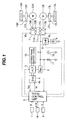
- FIG. 1 is a diagram illustrating an overall configuration of a drive system for an electrically driven dump truck according to one embodiment of the present invention.
- the drive system for the electrically driven dump truck includes: an accelerator pedal 1 ; a retard pedal 2 ; a shift lever 16 ; a total control unit 3 ; a prime mover 4 ; an alternating-current generator 5 ; other prime mover loads 18 ; a rectifying circuit 6 ; an inverter control unit 7 ; a chopper circuit 8 ; a grid resistor 9 ; a capacitor 10 ; a resistor 11 ; right and left electric motors (for example, induction motors) 12 R, 12 L; speed reducers 13 R, 13 L; tires 14 R, 14 L; and electromagnetic pickup sensors 15 R, 15 L.
- an accelerator pedal 1 ; a retard pedal 2 ; a shift lever 16 ; a total control unit 3 ; a prime mover 4 ; an alternating-current generator 5 ; other prime mover loads 18 ; a rectifying circuit 6 ; an inverter control unit 7 ; a chopper circuit 8 ; a grid resistor 9 ; a capacitor 10
- the inverter control unit 7 includes: torque instruction operation units 71 R, 71 L that are used for the right and left electric motors 12 R, 12 L respectively; motor control operation units 72 R, 72 L; and inverters (switching elements) 73 R, 73 L.
- a manipulate signal p of the accelerator pedal 1 and a manipulate signal q of the retard pedal 2 are inputted into the total control unit 3 .
- the manipulate signals p and q become a signal for controlling the magnitude of the driving force, and a signal for controlling the magnitude of the retard force, respectively.
- the total control unit 3 When the accelerator pedal 1 is pressed down to cause the dump truck to move forward or backward, the total control unit 3 outputs, to the prime mover 4 , an instruction indicating the target revolution speed Nr.
- the actual revolution speed Ne On the prime mover 4 side, the actual revolution speed Ne is detected by a revolution speed sensor, which is not illustrated. Then, a signal indicating the actual revolution speed Ne is returned from the prime mover 4 to the total control unit 3 .
- the prime mover 4 is a diesel engine that is equipped with an electronic governor 4 a .
- the electronic governor 4 a receives an instruction indicating the target revolution speed Nr
- the electronic governor 4 a controls the fuel injection amount so that the prime mover 4 revolves at the target revolution speed Nr.
- the alternating-current generator 5 is connected to the prime mover 4 .
- the alternating-current generator 5 performs alternating current generation.
- the electric power obtained by the alternating current generation is rectified by the rectifying circuit 6 before the electric power is accumulated in the capacitor 10 .
- a direct-current voltage value becomes V.
- the alternating-current generator 5 feeds back a voltage value, into which the direct-current voltage V is divided by the detection resistor 11 .
- the total control unit 3 controls the alternating-current generator 5 so that the voltage value in question becomes a specified constant voltage V 0 .
- the electric power generated by the alternating-current generator 5 is supplied to the right and left electric motors 12 R, 12 L through the inverter control unit 7 .
- the total control unit 3 controls the supply of the electric power so that the electric power required for the electric motors 12 R, 12 L is supplied.
- the horsepower MR, ML of the right and left electric motors 12 R, 12 L, which is instructed from the total control unit 3 , and the rotational speed ⁇ R, ⁇ L of the electric motors 12 R, 12 L, which is detected by the electromagnetic pickups 15 R, 15 L, are inputted into the inverter control unit 7 . Then, the inverter control unit 7 drives the electric motors 12 R, 12 L at a slip ratio of greater than 0 through the torque instruction operation units 71 R, 71 L, the motor control operation units 72 R, 72 L, and the inverters (switching elements) 73 R, 73 L respectively.
- the right and left rear wheels (tires) 14 R, 14 L are connected to the electric motors 12 R, 12 L through the speed reducers 13 R, 13 L respectively.
- the electromagnetic pickups 15 R, 15 L are typically sensors for detecting the peripheral speed of one gear teeth included in the speed reducers 13 R, 13 L respectively.
- a gear used for detection may also be given to a driving shaft inside the electric motor 12 R, or to a driving shaft to which the speed reducer 13 R and the tire 14 R are connected, so that the electromagnetic pickup 15 R is located at the position of the gear.
- the total control unit 3 controls the alternating-current generator 5 so that the alternating-current generator 5 does not generate electricity.
- the inverter control unit 7 applies the brake force to a car body which travels by driving each of the electric motors 12 R, 12 L at a slip ratio of greater than 0.
- each of the electric motors 12 R, 12 L acts as an electric generator.
- each of the electric motors 12 R, 12 L works so that the capacitor 10 is charged by a rectifying function that is built-into the inverter control unit 7 .
- the chopper circuit 8 works so that the direct-current voltage value V becomes a predetermined direct-current voltage value V 1 .
- an electric current is fed to the grid resistor 9 to transform the electric energy into the thermal energy.
- FIG. 2 is a diagram illustrating the relationship between the revolution speed Ne (the actual revolution speed) and output torque Te of the prime mover 4 .
- FIG. 3 is a diagram illustrating fuel injection characteristics of the electronic governor 4 a.
- Nr the target revolution speed
- Nrmax the maximum revolution speed (the rated revolution speed) Nrmax
- Nr ⁇ Nrmax the droop control or the isochronous control may be selected.
- straight lines R 1 , R 2 , R 3 indicate torque characteristics of the prime mover 4 in a control area of the electronic governor 4 a .
- the droop control will be described.
- the output torque of the prime mover 4 reaches a point C of an area Y 1 , where the prime mover 4 will stall in a short time.
- the area Y 0 control area of the electronic governor 4 a
- the area Y 1 indicates a state in which the prime mover 4 leaves no margin for output.
- the straight line R 1 of the droop control has specified inclination.
- the electronic governor 4 a controls the fuel injection amount so that the output torque is increased with the revolution speed Ne of the prime mover being decreased.
- the straight line R 2 of the droop control also has specified inclination.
- the electronic governor 4 a controls the fuel injection amount so that the output torque is increased with the revolution speed Ne of the prime mover being decreased.
- the torque is not changed by a range of change in revolution speed.
- an actual electronic governor has a range of change in revolution speed, whose value approximately ranges from 10 to 20 rpm.
- FIG. 3 is a chart illustrating the relationship between the instantaneous revolution speed deviation ⁇ N and the fuel injection amount Q.
- points A 1 , B 1 , Y 1 , C 1 correspond to the points A, B, Y, C shown in FIG. 2 respectively.
- the fuel injection amount increases as follows: A 1 ->B 1 ->Y 1 .
- an operating point of the prime mover 4 changes as follows: A->B->Y. Because the fuel injection amount does not increase to a value that is higher than the point Y 1 , if the load of the prime mover 4 exceeds the point Y 1 , the operating point changes as follows: Y->C. Accordingly, if the load further increases from this state, the prime mover 4 will stall.
- FIG. 4 is a functional block diagram illustrating the processing steps.
- FIGS. 5 through 7 are flowcharts each illustrating the processing steps. The processing steps will be described mainly according to the flowcharts shown in FIGS. 5 through 7 , and supplementarily by use of the functional block diagram shown in FIG. 4 , as below.
- the process starts from START; and when the processing steps are performed up to END, the process returns to START again.
- the operation amount of an accelerator pedal (hereinafter referred to as the accelerator operation amount) p is read out.
- a target prime mover horsepower Fr corresponding to the accelerator operation amount p is calculated with reference to a data map stored in a memory (a block 200 shown in FIG. 4 ).
- the data map shows the relationship between the accelerator operation amount and the target prime mover horsepower, the relationship being expressed by a function Fr(p) shown in FIG. 8 .
- the function Fr(p) is set so that if the accelerator operation amount p changes from 0, which means no operation, to pmax that is the maximum, a target horsepower Fr of the prime mover 4 changes from Fmin to Fmax as shown in FIG. 8 .
- FIG. 8 For example, in FIG.
- the target prime mover horsepower Fr reaches Fmax that is the maximum.
- the accelerator operation amount px at the point X is, for example, about 90% of the maximum operation amount pmax.
- a step 103 from the target prime mover horsepower Fr, the target revolution speed Nr of the prime mover 3 corresponding to the target prime mover horsepower Fr is calculated with reference to a data map stored in the memory (a block 202 shown in FIG. 4 ).
- the data map shows the relationship between the target horsepower and the target revolution speed, and is expressed by a function Nr(Fr) shown in FIG. 9 .
- Nr Nrmax (for example, 2000 rpm).
- the target revolution speed Nr is transmitted to the prime mover 4 as an instruction of the electronic governor 4 a .
- the prime mover 4 is driven so that the prime mover 4 revolves at the target revolution speed Nr.
- a step 104 the state quantity F/R indicating a state of a position of the shift lever 16 is inputted.
- N neutral
- F forward
- R reverse
- step 105 , 106 , 107 fundamental target horsepower Mr 1 of each of the electric motors 12 R, 12 L is calculated on the basis of F/R.
- F/R a data map stored in the memory, which shows the relationship between the accelerator operation amount for traveling forward and the target motor horsepower, is read out. The relationship is expressed by a function hF(p) shown in FIG. 10 .
- a data map stored in the memory which shows the relationship between the accelerator operation amount for traveling backward and the target motor horsepower, is read out.
- the relationship is expressed by a function hR(p) shown in FIG. 11 .
- H increases; an increase rate of H is increased from a point B; and at a point C at which the accelerator operation amount is lower than pmax, H reaches the maximum horsepower HFmax that can be generated by each of the electric motors 12 R, 12 L.
- the target motor horsepower H increases.
- the maximum value HRmax of the target motor horsepower is set at a value that is smaller than the maximum value HFmax of the function hF(p) used for traveling forward.
- the target motor horsepower for traveling backward may also be determined by multiplying the target motor horsepower, which has been determined by the function hF(p) used for traveling forward, by a positive constant whose value is smaller than 1.
- the accelerator operation amount pc at the point C shown in FIG. 10 is, for example, about 95% of the maximum operation amount pmax.
- a step 109 the actual revolution speed Ne of the prime mover 4 is read out.
- a step 110 with reference to a data map of the revolution speed and the maximum output horsepower of the prime mover 4 , the relationship being expressed by a function f(Ne) shown in FIG. 12 , and with reference to a data map of the revolution speed and the other prime mover load loss horsepower, the relationship being expressed by a function g(Ne) shown in FIG.
- the functions f(Ne) and g(Ne) are created in the following manner.
- the function f(Ne) is used to determine the maximum output horsepower that can be generated by the prime mover 4 .
- the function f 1 (Ne), the function f 2 (Ne), and the function f 3 (Ne) are combined into the function f(Ne).
- Nrmin for example, 750 rpm
- Nrmax for example, 2000 rpm
- the maximum output horsepower f(Ne) which can be generated by the prime mover 4 changes from the minimum value Fmin up to the maximum value Fmax.
- the prime mover 4 drives not only the alternating-current generator 5 but also components including: a cooling fan (not illustrated) used for sending air to a radiator; an oil hydraulic pump for driving hydraulic equipment that is used to move a vessel of the dump truck up and down, and that is used to perform steering operation; and a second electric generator (not illustrated) for driving an electric fan (not illustrated) that is used to cool the alternating-current generator 5 , the grid resistor 9 , the electric motors 12 R, 12 L, and the control units 3 , 7 .
- these components are illustrated as the other prime mover loads 18 .
- Horsepower values, which are assigned beforehand to drive the other prime mover loads 18 are expressed by g(Ne) shown in FIG. 12 .
- the horsepower g(Ne) is set at values which are slightly larger than those of the horsepower actually consumed by the other prime mover loads 18 so that a sufficient margin of the horsepower g(Ne) is left. In this specification, this horsepower is called the loss horsepower.
- the function g 1 (Ne), the function g 2 (Ne), and the function g 3 (Ne) are combined into the loss horsepower g(Ne).
- the function g 1 (Nr) if the actual revolution speed Ne of the prime mover 4 changes from Nrmin (for example, 750 rpm) up to Nrmax (for example, 2000 rpm), the loss horsepower g 1 (Ne) changes from the minimum value Gmin up to the maximum value Gmax.
- Mr which is the difference (f(Ne) g(Ne)) between f(Ne) and g(Ne), is the total effective available maximum horsepower for the electric motors 12 R, 12 L.
- Mr (f(Ne) ⁇ g(Ne)) is the available maximum horsepower (an assigned horsepower value) for the electric motors 12 R, 12 L, which are used for traveling, out of the maximum output horsepower f(Ne) that can be generated by the prime mover 4 .
- Mr 2 is used as a limit value for the above-described fundamental target horsepower Mr 1 .
- Mr 2 With respect to the maximum value HFmax of the above-described function hF(P) used for traveling forward, Mr 2 ⁇ HFmax.
- a step 113 the difference (revolution speed deviation) ⁇ N between the target revolution speed Nr of the prime mover 4 and the actual revolution speed Ne of the prime mover 4 is calculated (a block 220 shown in FIG. 4 ).
- ⁇ N Ne ⁇ Nr
- ⁇ N ⁇ 0 is a state in which the output of the prime mover is not sufficient;
- ⁇ N>0 is a state in which the output of the prime mover is sufficient.
- ⁇ N 3 is a value that falls within the range of ⁇ N ⁇ 0, whereas ⁇ N 4 is a value that falls within the range of ⁇ N>0.
- a step 117 the target motor horsepower Mr 2 , which has been calculated in the step 111 , is multiplied by Kp to determine the target motor horsepower Mr 3 (block 226 shown in FIG. 4 ).
- Mr 3 Kp ⁇ Mr 2
- Mr 2 becomes a final limit value for the above-described target motor horsepower Mr 3 , and for the fundamental target motor horsepower Mr 1 that has been calculated in the steps 105 , 106 , 107 .
- Mr min( Mr 1 ,Mr 3)
- the target motor horsepower Mr 3 is used as a limit value for the target motor horsepower Mr 1 ; and a limit is placed so that the target motor horsepower Mr does not exceed Mr 3 that is a final targeted value given to the electric motors 12 R, 12 L.
- Tr 1 R K 1 ⁇ Mr/ ⁇ R
- Tr 1 L K 1 ⁇ Mr/ ⁇ L
- K1 Constant used to calculate the torque from the horsepower and the rotational speed.
- the load torque of the electric motors 12 R, 12 L increases, and accordingly the motor rotational speed ⁇ R, ⁇ L decreases, with the result that the target motor torque Tr 1 R, Tr 1 L increases in response to the increase in load torque respectively.
- the target motor torque Tr 1 R, Tr 1 L decreases respectively.
- the target motor horsepower Mr is increased, the target motor torque Tr 1 R, Tr 1 L increases in response to the increase in target motor horsepower Mr respectively.
- the instantaneous motor load torque is constant, the motor rotational speed ⁇ R, ⁇ L increases respectively.
- the target motor horsepower is decreased in a state in which the motor load torque is kept constant, the motor rotational speed ⁇ R, ⁇ L decreases respectively.
- a step 121 with reference to a data map expressed in a function Mmax( ⁇ ) shown in FIG. 15 , upper limit Mmax( ⁇ R), Mmax( ⁇ L) of motor torque instructions corresponding to the rotational speed ⁇ R, ⁇ L of the electric motors 12 R, 12 L are determined respectively (blocks 234 , 236 shown in FIG. 4 ).
- the upper limit Mmax( ⁇ R), Mmax( ⁇ L) of the motor torque instructions are Mmax( ⁇ 1 ) respectively.
- the function Mmax( ⁇ ) is a data map of the rotational speed of each motor and the maximum output torque of the each motor.
- the function Mmax( ⁇ ) is predetermined on the basis of the following: the maximum value of current, which the inverter 73 R, 73 L can supply to the electric motors 12 R, 12 L respectively; an output limit of a driver element such as IGBT or GTO included in the inverters 73 R, 73 L; and the strength of each motor axis.
- a step 122 the upper limit Mmax( ⁇ R), Mmax( ⁇ L) of the motor torque, which have been determined in the step 121 , are compared with the first target motor torque Tr 1 R, Tr 1 L determined in the step 120 , and then the torque whose value is smaller is used as the second target motor torque TrR, TrL respectively (blocks 238 , 240 shown in FIG. 4 ).
- TrR min( M max( ⁇ R ), Tr 1 R )
- TrL min( M max( ⁇ L ), Tr 1 L )
- Processing performed in the steps 101 through 118 is processing performed by the total control unit 3 .
- Processing performed in the step 119 through 122 is processing performed by the torque instruction operation units 71 R, 71 L of the inverter control unit 7 .
- a step 123 the motor control operation units 72 R, 72 L included in the inverter control unit 7 control the inverters 73 R, 73 L in response to the target motor torque TrR, TrL so that the torque of the electric motors 12 R, 12 L is controlled respectively.
- a processing function executed in the steps 101 through 103 forms target revolution speed calculation means for calculating the target revolution speed Nr in response to the operation amount of the accelerator pedal 1 .
- a processing function executed in the steps 104 through 123 (the blocks 204 through 240 ), and the motor control operation units 72 R, 72 L of the inverter control unit 7 , form motor control means for controlling the inverters 73 R, 73 L in response to the operation amount of the accelerator pedal 1 so as to control the electric motors 12 R, 12 L respectively.
- the electronic governor 4 a controls the fuel injection amount for the prime mover 4 on the basis of the target revolution speed Nr.
- the electronic governor 4 a is so configured that when the target revolution speed Nr is set at least at the maximum revolution Nrmax, the control of the fuel injection amount becomes the droop control.
- a processing function executed in the steps 105 , 106 , 107 forms first target output horsepower calculation means for calculating target motor horsepower Mr 1 (first target motor horsepower) corresponding to the operation amount p of the accelerator pedal 1 .
- a processing function executed in the steps 113 through 117 forms speed sensing control means for modifying the available maximum horsepower (f(Ne) ⁇ g(Ne)) for the electric motors for traveling 12 R, 12 L such that the available maximum horsepower increases when the actual revolution speed Ne of the prime mover is higher than the target revolution speed Nr, and the increased maximum horsepower decreases with the decrease in the actual revolution speed of the prime mover 4 .
- a processing function executed in the steps 110 through 117 includes the speed sensing control means, and forms second target motor horsepower calculation means for determining, as second target motor horsepower Mr 3 , the available maximum horsepower that has been modified by the speed sensing control means.
- a processing function executed in the step 118 forms target motor horsepower limiting means for limiting the first target motor horsepower Mr 1 so that the first target motor horsepower Mr 1 does not exceed the second target motor horsepower Mr 3 , thereby to generate the target motor horsepower Mr (the second target motor horsepower).
- a processing function executed in the steps 119 through 123 (the blocks 230 through 240 shown in FIG.
- inverter control means for determining the first target motor torque Tr 1 R, Tr 1 L of each of the two electric motors 12 R, 12 L on the basis of the third target motor horsepower Mr so as to control the inverters 73 R, 73 L respectively.
- the speed sensing control means (the blocks 220 through 226 shown in FIG. 4 ) functions when the target revolution speed Nr of the prime mover 4 is set at least at the maximum revolution speed, and does not function in all other cases.
- a processing function executed in the steps 110 , 111 forms maximum horsepower calculation means for subtracting the loss horsepower g(Ne), which is required to drive the other prime mover loads 18 other than the alternating-current generator 5 , from the maximum output horsepower f(Ne) that can be output by the prime mover 4 , and thereby for determining the available maximum horsepower (f(Ne) ⁇ g(Ne)) for the electric motors 12 R, 12 L for traveling:
- the control by the speed sensing control means (the steps 113 through 117 , the blocks 220 through 226 shown in FIG. 4 ) is referred to as “speed sensing control”; and the control by the maximum horsepower calculation means (the steps 110 , 111 , the blocks 210 , 212 , 214 shown in FIG. 4 ), and by the target motor horsepower limiting means (the step 118 , the block 228 shown in FIG. 4 ), is referred to as “total horsepower control”. Moreover, the control into which the speed sensing control and the total horsepower control are combined is referred to as “speed sensing total horsepower control”.
- Fmax is calculated as the target horsepower Fr of the prime mover 4 in a block 200 shown in FIG. 4
- the electronic governor 4 a controls the fuel injection amount so that the prime mover 4 revolves at the target revolution speed Nrmax. As described above, if Nr Nrmax, the electronic governor 4 a is kept under the droop control.
- the target motor horsepower HFmax corresponding to nearly the maximum operation amount of the accelerator pedal is calculated as the fundamental target horsepower Mr 1 of the electric motors 12 R, 12 L.
- a revolution speed deviation ⁇ N which is a deviation of the actual revolution speed Ne from the target revolution speed Nr of the prime mover 4 .
- the target motor horsepower Mr 2 is multiplied by the horsepower coefficient Kp to calculate the target motor horsepower Mr 3 .
- the smaller value is selected from values of the target motor horsepower Mr 1 and the target motor horsepower Mr 3 to generate the target motor horsepower Mr.
- the target motor torque TrR, TrL of the right and left electric motors 12 R, 12 L is calculated respectively.
- the target motor torque TrR, TrL is given as the instructed horsepower of the electric motors 12 R, 12 L to the motor control operation units 72 R, 72 L included in the inverter control unit 7 respectively.
- the inverters 73 R, 73 L are controlled according to the target motor torque TrR, TrL so that the torque of the electric motors 12 R, 12 L is controlled respectively.
- the speed sensing total horsepower control is performed in the blocks 220 through 226 .
- the speed sensing total horsepower control makes it possible to make full use of the output horsepower up to the output limit of the prime mover 4 , and thereby to effectively utilize the prime mover horsepower on the motor side (described later).
- the target horsepower Fr whose value is smaller than Frmax is calculated in the block 200 shown in FIG. 4 .
- the target revolution speed Nr whose value is lower than Nrmax is calculated in the block 202 (Nr ⁇ Nrmax) so that the fuel injection amount of the prime mover 4 is controlled in response to the target revolution speed Nr.
- Nr ⁇ Nrmax on the electric motor side, Kp 1, which is set in the block 223 , is selected in the block 222 so that the speed sensing control is disabled.
- the first target motor horsepower is limited not so as to exceed the target motor horsepower Mr 3 thereby to determine the target motor horsepower Mr.
- the torque of the electric motors 12 R, 12 L is controlled in response to the target motor torque TrR, TrL that has been determined by the target motor horsepower Mr respectively.
- Nr ⁇ Nrmax the processing (the speed sensing control) described in the blocks 220 through 226 , which uses the revolution speed deviation ⁇ N, is disabled. Accordingly, the total horsepower control which does not include the speed sensing control is performed.
- the target motor horsepower H for traveling backward is calculated in the block 208 .
- the maximum value HRmax of the target motor horsepower H in the function hR(P) used for traveling backward is set at a slightly smaller value. Accordingly, in the block 228 shown in FIG. 4 , the target motor horsepower Mr 1 is selected, and then the torque of the electric motors 12 R, 12 L is controlled without being limited by the target motor horsepower Mr 3 .
- FIG. 16 is a functional block diagram illustrating, as a comparative example, a drive system used in a case where the total horsepower control which does not include the speed sensing control is performed, the functional block diagram being similar to FIG. 4 . Similar reference numerals are used in FIG. 16 to designate parts that are similar to those shown in FIG. 4 . Because the speed sensing control is not performed in the comparative example shown in FIG. 16 , the blocks 220 through 226 shown in FIG. 4 (the steps 112 through 117 shown in FIG. 6 ) are not included. Therefore, the target motor horsepower Mr 2 , which has been calculated in the blocks 210 through 216 , is compared with the target motor horsepower Mr 1 just as it is in the block 228 .
- fr(Nr) is equivalent to the function f 1 (Ne) of the maximum output horsepower that can be output by the prime mover 4 , the function f 1 (Ne) being shown in FIG. 12 .
- the straight line D indicates horsepower characteristics corresponding to the straight line R 1 of the droop control shown in a diagram illustrating prime mover output torque characteristics in FIG. 2 .
- the actual revolution speed Ne of the prime mover 4 is determined with reference to the functions f(Ne), g(Ne) shown in FIG. 12 to calculate values of f(Ne), g(Ne) corresponding to the maximum revolution speed Nrmax.
- the function f(Ne) expresses the maximum output horsepower that can be generated by the prime mover 4 ; and the function g(Ne) expresses a value of the horsepower (loss horsepower) that is preassigned to drive the other prime mover loads 18 .
- This loss horsepower is determined on the basis of an estimated value of the horsepower to be consumed by the other prime mover loads 18 .
- the actual consumed horsepower of the other prime mover loads 18 is a value that changes in response to operating situations.
- the change ranges from 10 to 20% of the maximum output horsepower of the prime mover 4 , which makes it difficult to estimate the actual consumed horsepower.
- a fan for cooling engine oil automatically repeats operation and stop, and the horsepower consumed by the fan becomes about from 5 to 10% of the output horsepower of the prime mover 4 . Therefore, if the loss horsepower of the other prime mover loads 8 is set at a certain estimated value, the actual consumed horsepower may become larger than the estimated value, and may also become smaller than the estimated value. If the actual consumed horsepower becomes larger than the estimated value, there is a possibility that the prime mover 4 will stall. For this reason, it is necessary to set the loss horsepower g(Ne) at a value that is larger than that of the actual consumed horsepower with a sufficient margin of the loss horsepower g(Ne) being left.
- the loss horsepower g(Ne) is set at about 300 kW.
- FIG. 17 is a chart that indicates, with a X 1 point, an operating point of the prime mover 4 during traveling in a state in which the loss horsepower g(Ne) is set in this manner.
- the total horsepower control which includes the speed sensing control is performed for such a comparative example, it is possible to make full use of the output horsepower up to the output limit of the prime mover 4 , and thereby to effectively utilize the prime mover horsepower on the motor side.
- the operating point of the prime mover 4 moves from X 1 shown in FIG. 17 to the overload side where ⁇ N ⁇ 0.
- the dump track travels as described above, if the consumed horsepower of the other prime mover loads 8 increases for some reason or other (for example, due to a change in temperature), which causes the operating point X 2 shown in FIG. 17 to be further moved to the left side of FIG. 17 , the revolution speed deviation ⁇ N further decreases, causing the horsepower coefficient Kp calculated in the block 222 to decrease.
- the limit value of the target horsepower of each of the electric motors 12 R, 12 L (the target motor horsepower Mr 3 ) is increased to make full use of the horsepower up to the output limit of the prime mover 4 so that each of the electric motors 12 R, 12 L is driven.
- the limit value of the target horsepower of each of the electric motors 12 R, 12 L (the target motor horsepower Mr 3 ) is decreased to reduce the consumed horsepower of each of the electric motors 12 R, 12 L.
- the speed sensing control to be performed by the blocks 220 through 226 as described above may cause a malfunction.
- the accelerator pedal 1 is operated to a half extent, if the dump truck comes to an upward slope during traveling along a flat road at Nr ⁇ Nrmax, the traveling speed decreases. Accordingly, in order to keep the traveling speed constant, an operator increases the extent to which the operator presses down on the accelerator pedal 1 . In this case, a case where the speed sensing control is performed by the blocks 220 through 226 shown in FIG. 4 is considered.
- the prime mover 4 leaves a sufficient margin for output, and accordingly ⁇ N>0.
- the target motor horsepower Mr 1 increases. This causes the loads of the prime mover 4 to increase, and accordingly ⁇ N ⁇ 0.
- the horsepower coefficient Kp calculated in the block 222 decreases, and the target motor horsepower Mr 3 also decreases. Therefore, the target motor horsepower Mr 1 is limited by the target motor horsepower Mr 3 . Even if the accelerator pedal 1 is pressed down, the target torque Mr of the electric motors 12 R, 12 L decreases, which causes the traveling speed to decrease.
- the blocks 210 through 226 , and the block 228 which are shown in FIG. 3 , not the target torque but the target horsepower Mr 1 , Mr 2 , Mr 3 is determined as an instruction value of the electric motors 12 R, 12 L. Then, in the blocks 230 , 232 , the target horsepower Mr 3 is divided by the instantaneous motor rotational speed to calculate the first target motor torque Tr 1 R, Tr 1 L. Moreover, the target motor torque is compared with a value acquired from a function of the maximum torque, which is specific to the inverter, and the motors, so that a smaller value is controlled as the final target torque TrR, TrL.
- the target motor horsepower is calculated as a value to be directly calculated from the operation amount p of the accelerator pedal 1 .
- the operation amount of the accelerator pedal 1 is small, all of the target revolution speed of the prime mover 4 , the horsepower of the electric motors 12 R, 12 L, and the torque decrease. Therefore, in situations in which the operator wants to increase the torque with the operation amount of the accelerator pedal being decreased so that the horsepower to be applied to the electric motors 12 R, 12 L is decreased, the operator cannot properly operate the accelerator pedal. For example, at the time of starting traveling along an upward slope, only pressing down the accelerator pedal 1 to a small extent results in insufficient torque. Therefore, the operator is required to press down on the accelerator pedal 1 to a larger extent. However, while the operator is at a loss, the dump truck may also move backward because of the self-weight of the dump truck, which is dangerous.
- the target horsepower Mr is determined as an instructed value of the electric motors 12 R, 12 L.
- the target motor torque is calculated with reference to the instantaneous rotational speed of the electric motors 12 R, 12 L. so as to control the electric motors 12 r , 12 L.
- the rotational speed of each of the electric motors 12 R, 12 L is low, the operation amount of the accelerator pedal 1 is small. Accordingly, even if the horsepower applied to each of the electric motors 12 R, 12 L is small, it is possible to increase the output torque. Therefore, such a malfunction that the dump truck moves backward at the time of starting traveling along the upward slope does not occur.
- the target revolution speed Nr of the prime mover 4 is not directly determined from the operation amount p of the accelerator pedal 1 .
- the target horsepower Fr of the prime mover 4 is calculated by the function Fr(p) (block 200 ).
- the target revolution speed Nr is calculated by the function Nr(Fr) that is an inverse function of fr(Nr) shown in FIG. 12 (block 202 ). This makes it possible to modify the nonlinearity of the horsepower characteristics of the prime mover 4 .
- the horsepower coefficient Kp is determined as a horsepower modification value in the block 222 , and then the horsepower coefficient Kp is multiplied by the target motor horsepower Mr 2 to determine the target motor horsepower Mr 3 in the block 226 .
- a function of a revolution speed deviation ⁇ N and a function of a horsepower modification value ⁇ M are used as the functions in the block 222 so as to determine the horsepower modification value ⁇ M corresponding to the instantaneous revolution speed deviation ⁇ N, and that this horsepower modification value ⁇ M is added to the target motor horsepower Mr 2 to determine the target motor horsepower Mr 3 .
- the maximum output horsepower and the loss horsepower are determined from the actual revolution speed Ne of the prime mover 4 .
- the revolution speed which is used as the criterion of judgment, is not limited to one point (Nrmax).
- the revolution speed may also approximately range from 0 through 50 rpm.
- the loss horsepower g(Ne) of the other prime mover loads 8 is set at a value with a sufficient margin for an estimated value being left.
- the loss horsepower g(Ne) of the other prime mover loads 8 may also be set at a value, which is the same as, or approximately the same as, the estimated value, without leaving a sufficient margin for the estimated value.
- the target motor horsepower Mr 3 calculated in the block 226 as the result becomes lower than the loss horsepower g(Ne) as the set value, which makes it possible to prevent the prime mover 4 from stalling due to the overload of the prime mover 4 .
- the speed sensing control is not performed when Ne ⁇ Nrmax, it is necessary to set the horsepower coefficient Kp in the block 223 at a value having a sufficient margin (Kp is set at about 0.9) so that the consumed horsepower of the electric motors 12 R, 12 L for traveling does not excessively increase.
- the target motor horsepower Mr 3 in order to determine the target motor horsepower Mr 3 used to perform the speed sensing total horsepower control, is calculated by the following order: in the blocks 210 , 212 , separately determining the maximum output horsepower f(Ne) and the loss horsepower g(Ne); in the block 214 , determining the difference between the maximum output horsepower f(Ne) and the loss horsepower g(Ne); in the block 216 , multiplying the difference by 1 ⁇ 2 to determine the target motor horsepower Mr 2 ; and in the block 226 , multiplying the target motor horsepower Mr 2 by the horsepower coefficient Kp.
- this is merely an example.
- the order of calculation, and how to calculate Mr 3 are not limited to the example so long as Mr 3 whose value is the same is determined as a result of the calculation.
- the maximum output horsepower f(Ne) and the loss horsepower g(Ne) are determined by use of each of the functions f(Ne), g(Ne), and that in the block 214 , instead of determining the difference between the maximum output horsepower f(Ne) and the loss horsepower g(Ne), a function corresponding to f(Ne) ⁇ g(Ne) is provided beforehand so as to determine a value that is equivalent to the difference in question by one processing step.
- the difference f(Ne) ⁇ g(Ne) between the maximum output horsepower f(Ne) and the loss horsepower g(Ne) is determined before the difference is multiplied by 1 ⁇ 2, and by the horsepower coefficient Kp.
- the difference may also be multiplied by 1 ⁇ 2, and by the horsepower coefficient Kp, before the calculation in the block 214 .
- the multiplication may also be performed with the order of either 1 ⁇ 2 or the horsepower coefficient Kp being reversed.
- the electric motors 12 R, 12 L are induction motors, they may also be synchronous motors.
- a function which differs from the functions hF(P), hR(P) for determining the target motor horsepower in the blocks 206 , 208 , is used as the function Fr(P) used in the block 200 .
- a function which is the same as the functions hF(P), hR(P) for determining the target motor horsepower in the blocks 206 , 208 , may also be used.
- the prime mover 4 is driven so that the prime mover 4 outputs only the horsepower required for the electric motors 12 R, 12 L, it becomes possible to achieve the optimum prime mover control without waste.
Landscapes
- Engineering & Computer Science (AREA)
- Transportation (AREA)
- Mechanical Engineering (AREA)
- Chemical & Material Sciences (AREA)
- Combustion & Propulsion (AREA)
- Power Engineering (AREA)
- Automation & Control Theory (AREA)
- Hybrid Electric Vehicles (AREA)
- Electric Propulsion And Braking For Vehicles (AREA)
- Control Of Vehicle Engines Or Engines For Specific Uses (AREA)
Applications Claiming Priority (3)
| Application Number | Priority Date | Filing Date | Title |
|---|---|---|---|
| JP2006144378A JP4230493B2 (ja) | 2006-05-24 | 2006-05-24 | 電気駆動ダンプトラックの駆動システム |
| JP2006-144378 | 2006-05-24 | ||
| PCT/JP2007/059453 WO2007135849A1 (ja) | 2006-05-24 | 2007-05-07 | 電気駆動ダンプトラックの駆動システム |
Publications (2)
| Publication Number | Publication Date |
|---|---|
| US20090251090A1 US20090251090A1 (en) | 2009-10-08 |
| US7863837B2 true US7863837B2 (en) | 2011-01-04 |
Family
ID=38723161
Family Applications (1)
| Application Number | Title | Priority Date | Filing Date |
|---|---|---|---|
| US12/091,995 Active 2027-09-21 US7863837B2 (en) | 2006-05-24 | 2007-05-07 | Drive system for electrically driven dump truck |
Country Status (5)
| Country | Link |
|---|---|
| US (1) | US7863837B2 (enExample) |
| JP (1) | JP4230493B2 (enExample) |
| AU (1) | AU2007252710B2 (enExample) |
| DE (1) | DE112007000061B4 (enExample) |
| WO (1) | WO2007135849A1 (enExample) |
Cited By (4)
| Publication number | Priority date | Publication date | Assignee | Title |
|---|---|---|---|---|
| US20090048064A1 (en) * | 2006-06-06 | 2009-02-19 | Yasuo Tanaka | Drive system for electrically driven dump truck |
| US20090132116A1 (en) * | 2006-06-06 | 2009-05-21 | Yasuo Tanaka | Drive system for electrically driven dump truck |
| US10005355B2 (en) | 2014-01-28 | 2018-06-26 | General Electric Company | Integrated mounting and cooling apparatus, electronic device, and vehicle |
| US10073512B2 (en) | 2014-11-19 | 2018-09-11 | General Electric Company | System and method for full range control of dual active bridge |
Families Citing this family (10)
| Publication number | Priority date | Publication date | Assignee | Title |
|---|---|---|---|---|
| JP5780669B2 (ja) * | 2011-06-10 | 2015-09-16 | ボッシュ株式会社 | エンジン回転制御モード切替方法及びエンジン回転制御装置 |
| US8606448B2 (en) | 2011-06-29 | 2013-12-10 | Caterpillar Inc. | System and method for managing power in machine having electric and/or hydraulic devices |
| US8909434B2 (en) | 2011-06-29 | 2014-12-09 | Caterpillar, Inc. | System and method for controlling power in machine having electric and/or hydraulic devices |
| JP6066880B2 (ja) * | 2013-09-27 | 2017-01-25 | 株式会社クボタ | シリーズハイブリッドコンバイン |
| KR102307094B1 (ko) * | 2013-09-27 | 2021-10-01 | 가부시끼 가이샤 구보다 | 시리즈 하이브리드 콤바인 |
| CN103660971B (zh) * | 2013-12-16 | 2015-09-23 | 航天重型工程装备有限公司 | 一种电动轮矿用自卸车四轮驱动系统 |
| WO2016134319A1 (en) | 2015-02-19 | 2016-08-25 | Enphase Energy, Inc. | Method and apparatus for time-domain droop control with integrated phasor current control |
| JP7105526B2 (ja) | 2018-08-10 | 2022-07-25 | 日立建機株式会社 | 作業車両 |
| CN111431454B (zh) * | 2020-04-28 | 2021-09-21 | 中山大洋电机股份有限公司 | 无位置传感器矢量控制永磁电机估算转速可靠性判断方法 |
| AU2022297526A1 (en) | 2021-06-23 | 2024-02-08 | Outrider Technologies, Inc. | Motor stall and trailer lift |
Citations (9)
| Publication number | Priority date | Publication date | Assignee | Title |
|---|---|---|---|---|
| US5280223A (en) * | 1992-03-31 | 1994-01-18 | General Electric Company | Control system for an electrically propelled traction vehicle |
| US5289890A (en) * | 1991-12-10 | 1994-03-01 | Aisin Aw Co., Ltd. | Drive unit for electric motor vehicle |
| JPH1051905A (ja) | 1996-07-26 | 1998-02-20 | Tech Res & Dev Inst Of Japan Def Agency | 車両駆動装置 |
| US5939846A (en) * | 1997-09-04 | 1999-08-17 | General Electric Company | AC motorized wheel control system |
| US5988307A (en) * | 1995-05-19 | 1999-11-23 | Toyota Jidosha Kabushiki Kaisha | Power transmission apparatus, four-wheel drive vehicle with power transmission apparatus incorporated therein, method of transmitting power, and method of four-wheel driving |
| JP2001107762A (ja) | 1999-10-08 | 2001-04-17 | Tcm Corp | 産業用車両の走行駆動装置 |
| US6340847B1 (en) * | 1999-02-04 | 2002-01-22 | Toyota Jidosha Kabushiki Kaisha | Power output apparatus and method of controlling the same |
| US20030080704A1 (en) | 2001-10-30 | 2003-05-01 | Tsutomu Wakitani | Working machine |
| JP2003143706A (ja) | 2001-10-30 | 2003-05-16 | Honda Motor Co Ltd | 作業機 |
Family Cites Families (1)
| Publication number | Priority date | Publication date | Assignee | Title |
|---|---|---|---|---|
| JP2000115907A (ja) | 1998-10-09 | 2000-04-21 | Mitsubishi Electric Corp | 内燃機関型電気機関車用制御装置 |
-
2006
- 2006-05-24 JP JP2006144378A patent/JP4230493B2/ja active Active
-
2007
- 2007-05-07 DE DE112007000061.9T patent/DE112007000061B4/de not_active Expired - Fee Related
- 2007-05-07 US US12/091,995 patent/US7863837B2/en active Active
- 2007-05-07 WO PCT/JP2007/059453 patent/WO2007135849A1/ja not_active Ceased
- 2007-05-07 AU AU2007252710A patent/AU2007252710B2/en active Active
Patent Citations (9)
| Publication number | Priority date | Publication date | Assignee | Title |
|---|---|---|---|---|
| US5289890A (en) * | 1991-12-10 | 1994-03-01 | Aisin Aw Co., Ltd. | Drive unit for electric motor vehicle |
| US5280223A (en) * | 1992-03-31 | 1994-01-18 | General Electric Company | Control system for an electrically propelled traction vehicle |
| US5988307A (en) * | 1995-05-19 | 1999-11-23 | Toyota Jidosha Kabushiki Kaisha | Power transmission apparatus, four-wheel drive vehicle with power transmission apparatus incorporated therein, method of transmitting power, and method of four-wheel driving |
| JPH1051905A (ja) | 1996-07-26 | 1998-02-20 | Tech Res & Dev Inst Of Japan Def Agency | 車両駆動装置 |
| US5939846A (en) * | 1997-09-04 | 1999-08-17 | General Electric Company | AC motorized wheel control system |
| US6340847B1 (en) * | 1999-02-04 | 2002-01-22 | Toyota Jidosha Kabushiki Kaisha | Power output apparatus and method of controlling the same |
| JP2001107762A (ja) | 1999-10-08 | 2001-04-17 | Tcm Corp | 産業用車両の走行駆動装置 |
| US20030080704A1 (en) | 2001-10-30 | 2003-05-01 | Tsutomu Wakitani | Working machine |
| JP2003143706A (ja) | 2001-10-30 | 2003-05-16 | Honda Motor Co Ltd | 作業機 |
Cited By (5)
| Publication number | Priority date | Publication date | Assignee | Title |
|---|---|---|---|---|
| US20090048064A1 (en) * | 2006-06-06 | 2009-02-19 | Yasuo Tanaka | Drive system for electrically driven dump truck |
| US20090132116A1 (en) * | 2006-06-06 | 2009-05-21 | Yasuo Tanaka | Drive system for electrically driven dump truck |
| US8265849B2 (en) * | 2006-06-06 | 2012-09-11 | Hitachi Construction Machinery Co., Ltd. | Drive system for electrically driven dump truck |
| US10005355B2 (en) | 2014-01-28 | 2018-06-26 | General Electric Company | Integrated mounting and cooling apparatus, electronic device, and vehicle |
| US10073512B2 (en) | 2014-11-19 | 2018-09-11 | General Electric Company | System and method for full range control of dual active bridge |
Also Published As
| Publication number | Publication date |
|---|---|
| AU2007252710B2 (en) | 2010-06-17 |
| DE112007000061T5 (de) | 2008-09-04 |
| AU2007252710A1 (en) | 2007-11-29 |
| US20090251090A1 (en) | 2009-10-08 |
| WO2007135849A1 (ja) | 2007-11-29 |
| DE112007000061B4 (de) | 2024-10-31 |
| JP4230493B2 (ja) | 2009-02-25 |
| JP2007313992A (ja) | 2007-12-06 |
Similar Documents
| Publication | Publication Date | Title |
|---|---|---|
| US7863837B2 (en) | Drive system for electrically driven dump truck | |
| US8265849B2 (en) | Drive system for electrically driven dump truck | |
| US8249765B2 (en) | Drive system for electrically driven dump truck | |
| US20090132116A1 (en) | Drive system for electrically driven dump truck | |
| US8093843B2 (en) | Vehicle controller and control method | |
| US8427086B2 (en) | Brake resistor control | |
| US6692403B2 (en) | Series hybrid vehicle capable of operating without a battery | |
| JP2009011057A (ja) | 車両の制御装置 | |
| JP5637029B2 (ja) | 車両用発電制御装置 | |
| EP3272603B1 (en) | Control device and control method for hybrid vehicle | |
| JP4155962B2 (ja) | ハイブリッド車両 | |
| JP7401021B2 (ja) | ハイブリッド車両 | |
| JP6435968B2 (ja) | 車両の制御装置 | |
| JP2013255342A (ja) | モータ搭載自動車の駆動力制御装置 | |
| JP4311681B2 (ja) | 電気駆動ダンプトラックの駆動システム | |
| KR20120064344A (ko) | 친환경 자동차의 트랙션 제어장치 및 방법 | |
| JP4814202B2 (ja) | 電気駆動ダンプトラックの駆動システム | |
| JP2008044410A (ja) | 電気駆動ダンプトラックの駆動システム | |
| JP2012016188A (ja) | 作業車両の電動式走行駆動装置 | |
| JP2007313994A5 (enExample) | ||
| JP2016116397A (ja) | 回生制御装置 | |
| KR20120124692A (ko) | 하이브리드 차량의 엔진 토크 저감 제어 방법 |
Legal Events
| Date | Code | Title | Description |
|---|---|---|---|
| AS | Assignment |
Owner name: HITACHI CONSTRUCTION MACHINERY CO., LTD., JAPAN Free format text: ASSIGNMENT OF ASSIGNORS INTEREST;ASSIGNORS:TANAKA, YASUO;YASUDA, TOMOHIKO;YAGYU, TAKASHI;AND OTHERS;REEL/FRAME:020872/0603;SIGNING DATES FROM 20071022 TO 20071025 Owner name: HITACHI CONSTRUCTION MACHINERY CO., LTD., JAPAN Free format text: ASSIGNMENT OF ASSIGNORS INTEREST;ASSIGNORS:TANAKA, YASUO;YASUDA, TOMOHIKO;YAGYU, TAKASHI;AND OTHERS;SIGNING DATES FROM 20071022 TO 20071025;REEL/FRAME:020872/0603 |
|
| STCF | Information on status: patent grant |
Free format text: PATENTED CASE |
|
| FPAY | Fee payment |
Year of fee payment: 4 |
|
| MAFP | Maintenance fee payment |
Free format text: PAYMENT OF MAINTENANCE FEE, 8TH YEAR, LARGE ENTITY (ORIGINAL EVENT CODE: M1552) Year of fee payment: 8 |
|
| MAFP | Maintenance fee payment |
Free format text: PAYMENT OF MAINTENANCE FEE, 12TH YEAR, LARGE ENTITY (ORIGINAL EVENT CODE: M1553); ENTITY STATUS OF PATENT OWNER: LARGE ENTITY Year of fee payment: 12 |