US7826983B2 - Instrumented mobility assistance device - Google Patents
Instrumented mobility assistance device Download PDFInfo
- Publication number
- US7826983B2 US7826983B2 US11/650,361 US65036107A US7826983B2 US 7826983 B2 US7826983 B2 US 7826983B2 US 65036107 A US65036107 A US 65036107A US 7826983 B2 US7826983 B2 US 7826983B2
- Authority
- US
- United States
- Prior art keywords
- user
- contact
- sensor
- assistance device
- gait
- Prior art date
- Legal status (The legal status is an assumption and is not a legal conclusion. Google has not performed a legal analysis and makes no representation as to the accuracy of the status listed.)
- Expired - Fee Related, expires
Links
Images


Classifications
-
- A—HUMAN NECESSITIES
- A61—MEDICAL OR VETERINARY SCIENCE; HYGIENE
- A61H—PHYSICAL THERAPY APPARATUS, e.g. DEVICES FOR LOCATING OR STIMULATING REFLEX POINTS IN THE BODY; ARTIFICIAL RESPIRATION; MASSAGE; BATHING DEVICES FOR SPECIAL THERAPEUTIC OR HYGIENIC PURPOSES OR SPECIFIC PARTS OF THE BODY
- A61H3/00—Appliances for aiding patients or disabled persons to walk about
-
- A—HUMAN NECESSITIES
- A61—MEDICAL OR VETERINARY SCIENCE; HYGIENE
- A61B—DIAGNOSIS; SURGERY; IDENTIFICATION
- A61B5/00—Measuring for diagnostic purposes; Identification of persons
- A61B5/103—Detecting, measuring or recording devices for testing the shape, pattern, colour, size or movement of the body or parts thereof, for diagnostic purposes
- A61B5/1036—Measuring load distribution, e.g. podologic studies
- A61B5/1038—Measuring plantar pressure during gait
-
- A—HUMAN NECESSITIES
- A61—MEDICAL OR VETERINARY SCIENCE; HYGIENE
- A61H—PHYSICAL THERAPY APPARATUS, e.g. DEVICES FOR LOCATING OR STIMULATING REFLEX POINTS IN THE BODY; ARTIFICIAL RESPIRATION; MASSAGE; BATHING DEVICES FOR SPECIAL THERAPEUTIC OR HYGIENIC PURPOSES OR SPECIFIC PARTS OF THE BODY
- A61H3/00—Appliances for aiding patients or disabled persons to walk about
- A61H3/04—Wheeled walking aids for disabled persons
-
- B—PERFORMING OPERATIONS; TRANSPORTING
- B62—LAND VEHICLES FOR TRAVELLING OTHERWISE THAN ON RAILS
- B62B—HAND-PROPELLED VEHICLES, e.g. HAND CARTS OR PERAMBULATORS; SLEDGES
- B62B5/00—Accessories or details specially adapted for hand carts
- B62B5/0026—Propulsion aids
-
- G—PHYSICS
- G01—MEASURING; TESTING
- G01C—MEASURING DISTANCES, LEVELS OR BEARINGS; SURVEYING; NAVIGATION; GYROSCOPIC INSTRUMENTS; PHOTOGRAMMETRY OR VIDEOGRAMMETRY
- G01C22/00—Measuring distance traversed on the ground by vehicles, persons, animals or other moving solid bodies, e.g. using odometers, using pedometers
- G01C22/006—Pedometers
-
- A—HUMAN NECESSITIES
- A45—HAND OR TRAVELLING ARTICLES
- A45B—WALKING STICKS; UMBRELLAS; LADIES' OR LIKE FANS
- A45B1/00—Sticks with supporting, hanging or carrying means
- A45B1/02—Walking sticks with rollers for carrying parcels or the like
-
- A—HUMAN NECESSITIES
- A45—HAND OR TRAVELLING ARTICLES
- A45B—WALKING STICKS; UMBRELLAS; LADIES' OR LIKE FANS
- A45B3/00—Sticks combined with other objects
-
- A—HUMAN NECESSITIES
- A45—HAND OR TRAVELLING ARTICLES
- A45B—WALKING STICKS; UMBRELLAS; LADIES' OR LIKE FANS
- A45B3/00—Sticks combined with other objects
- A45B3/08—Sticks combined with other objects with measuring or weighing appliances
-
- A—HUMAN NECESSITIES
- A45—HAND OR TRAVELLING ARTICLES
- A45B—WALKING STICKS; UMBRELLAS; LADIES' OR LIKE FANS
- A45B9/00—Details
-
- A—HUMAN NECESSITIES
- A61—MEDICAL OR VETERINARY SCIENCE; HYGIENE
- A61B—DIAGNOSIS; SURGERY; IDENTIFICATION
- A61B5/00—Measuring for diagnostic purposes; Identification of persons
- A61B5/40—Detecting, measuring or recording for evaluating the nervous system
- A61B5/4005—Detecting, measuring or recording for evaluating the nervous system for evaluating the sensory system
- A61B5/4023—Evaluating sense of balance
-
- A—HUMAN NECESSITIES
- A61—MEDICAL OR VETERINARY SCIENCE; HYGIENE
- A61H—PHYSICAL THERAPY APPARATUS, e.g. DEVICES FOR LOCATING OR STIMULATING REFLEX POINTS IN THE BODY; ARTIFICIAL RESPIRATION; MASSAGE; BATHING DEVICES FOR SPECIAL THERAPEUTIC OR HYGIENIC PURPOSES OR SPECIFIC PARTS OF THE BODY
- A61H1/00—Apparatus for passive exercising; Vibrating apparatus ; Chiropractic devices, e.g. body impacting devices, external devices for briefly extending or aligning unbroken bones
- A61H1/02—Stretching or bending or torsioning apparatus for exercising
- A61H2001/0211—Walking coordination of arms and legs
-
- A—HUMAN NECESSITIES
- A61—MEDICAL OR VETERINARY SCIENCE; HYGIENE
- A61H—PHYSICAL THERAPY APPARATUS, e.g. DEVICES FOR LOCATING OR STIMULATING REFLEX POINTS IN THE BODY; ARTIFICIAL RESPIRATION; MASSAGE; BATHING DEVICES FOR SPECIAL THERAPEUTIC OR HYGIENIC PURPOSES OR SPECIFIC PARTS OF THE BODY
- A61H2201/00—Characteristics of apparatus not provided for in the preceding codes
- A61H2201/01—Constructive details
- A61H2201/0173—Means for preventing injuries
-
- A—HUMAN NECESSITIES
- A61—MEDICAL OR VETERINARY SCIENCE; HYGIENE
- A61H—PHYSICAL THERAPY APPARATUS, e.g. DEVICES FOR LOCATING OR STIMULATING REFLEX POINTS IN THE BODY; ARTIFICIAL RESPIRATION; MASSAGE; BATHING DEVICES FOR SPECIAL THERAPEUTIC OR HYGIENIC PURPOSES OR SPECIFIC PARTS OF THE BODY
- A61H2201/00—Characteristics of apparatus not provided for in the preceding codes
- A61H2201/50—Control means thereof
- A61H2201/5058—Sensors or detectors
- A61H2201/5061—Force sensors
-
- A—HUMAN NECESSITIES
- A61—MEDICAL OR VETERINARY SCIENCE; HYGIENE
- A61H—PHYSICAL THERAPY APPARATUS, e.g. DEVICES FOR LOCATING OR STIMULATING REFLEX POINTS IN THE BODY; ARTIFICIAL RESPIRATION; MASSAGE; BATHING DEVICES FOR SPECIAL THERAPEUTIC OR HYGIENIC PURPOSES OR SPECIFIC PARTS OF THE BODY
- A61H2201/00—Characteristics of apparatus not provided for in the preceding codes
- A61H2201/50—Control means thereof
- A61H2201/5058—Sensors or detectors
- A61H2201/5064—Position sensors
-
- A—HUMAN NECESSITIES
- A61—MEDICAL OR VETERINARY SCIENCE; HYGIENE
- A61H—PHYSICAL THERAPY APPARATUS, e.g. DEVICES FOR LOCATING OR STIMULATING REFLEX POINTS IN THE BODY; ARTIFICIAL RESPIRATION; MASSAGE; BATHING DEVICES FOR SPECIAL THERAPEUTIC OR HYGIENIC PURPOSES OR SPECIFIC PARTS OF THE BODY
- A61H2201/00—Characteristics of apparatus not provided for in the preceding codes
- A61H2201/50—Control means thereof
- A61H2201/5058—Sensors or detectors
- A61H2201/5079—Velocity sensors
-
- A—HUMAN NECESSITIES
- A61—MEDICAL OR VETERINARY SCIENCE; HYGIENE
- A61H—PHYSICAL THERAPY APPARATUS, e.g. DEVICES FOR LOCATING OR STIMULATING REFLEX POINTS IN THE BODY; ARTIFICIAL RESPIRATION; MASSAGE; BATHING DEVICES FOR SPECIAL THERAPEUTIC OR HYGIENIC PURPOSES OR SPECIFIC PARTS OF THE BODY
- A61H2230/00—Measuring physical parameters of the user
- A61H2230/62—Posture
-
- B—PERFORMING OPERATIONS; TRANSPORTING
- B62—LAND VEHICLES FOR TRAVELLING OTHERWISE THAN ON RAILS
- B62B—HAND-PROPELLED VEHICLES, e.g. HAND CARTS OR PERAMBULATORS; SLEDGES
- B62B5/00—Accessories or details specially adapted for hand carts
- B62B5/0026—Propulsion aids
- B62B5/0069—Control
-
- B—PERFORMING OPERATIONS; TRANSPORTING
- B62—LAND VEHICLES FOR TRAVELLING OTHERWISE THAN ON RAILS
- B62B—HAND-PROPELLED VEHICLES, e.g. HAND CARTS OR PERAMBULATORS; SLEDGES
- B62B5/00—Accessories or details specially adapted for hand carts
- B62B5/0026—Propulsion aids
- B62B5/0069—Control
- B62B5/0073—Measuring a force
Definitions
- This description relates to mobility-assistance devices.
- Mobility-assistance devices are used to enable or enhance a mobility of one or more users.
- Such devices provide an amount of mobility assistance ranging from minimal assistance, such as, for example, canes or walking sticks, all the way to virtually complete assistance, such as, for example, self-powered wheel chairs.
- the level of mobility assistance is often inversely proportional to a level of independence of the user, so that, for example, a user with a cane is generally able to navigate in areas that are less accessible to a user of a wheelchair.
- One type of mobility assistance device is known as a walker, and is known to provide significant mobility assistance, while still allowing or requiring the user to supply meaningful effort.
- the user may maintain a certain level of fitness, vitality, and feeling of empowerment, any of which may otherwise be compromised if the user accepts lower levels of mobility and/or a higher degree of mobility assistance.
- the walker may provide a good balance between a level of assistance that is required and a level of independence that is desired.
- Various types of users exist who may benefit from such mobility assistance devices. For example, elderly users with limited mobility may use a walker to provide weight support, balance, or other mobility assistance. Other clinical populations, such as, for example, the injured or infirm, may benefit from such mobility assistance, as well.
- a method includes receiving a sensor signal from a sensor associated with a mobility-assistance device operated on a surface by a user, relating the sensor signal to a contact attribute associated with a contact of the user with the surface, and determining a gait characteristic of the user, based on the contact attribute.
- receiving the sensor signal from the sensor may include receiving the sensor signal from the sensor associated with a handle of the mobility-assistance device. Also, receiving the sensor signal from the sensor may include receiving a force signal or a moment signal associated with a force exerted by the user on the mobility assistance device.
- Relating the sensor signal to a contact attribute may include relating the sensor signal to an initial foot contact of a foot of the user with the surface, or to a foot-off contact of a foot of the user from the surface.
- Relating the sensor signal to a contact attribute also may include correlating gait-related signal variations of the sensor signal with the contact attribute.
- relating the sensor signal to a contact attribute may include determining a peak of the sensor signal, and correlating the peak with the contact attribute.
- Determining the gait characteristic of the user may include determining one or more of a group of gait characteristics that includes a gait step count, a gait pace, or timing information of different gait phases. Determining the gait characteristic of the user may include determining the gait characteristic based on a supplemental sensor signal from a supplemental sensor associated with the mobility assistance device. In this case, determining the gait characteristic of the user may include determining one or more of a group of gait characteristics that includes an instantaneous walking velocity, an average walking velocity, a step length of the user, or a stride length of the user. In another implementation, determining the gait characteristic of the user may include determining a stability measure of the mobility assistance device.
- a longitudinal analysis may be performed based on the gait characteristic.
- performing the longitudinal analysis may include collecting data associated with the gait characteristic over a time period, and performing a trend analysis on the data.
- a system in another general aspect, includes a data acquisition system that is operable to receive a sensor signal from a sensor associated with a mobility assistance device, and a use analyzer that is operable to relate the sensor signal to a contact attribute associated with a contact of a user of the mobility assistance device with an underlying surface, and further operable to determine a gait characteristic of the user, based on the contact attribute.
- the senor may include at least one of a force or moment sensor.
- the contact attribute may include at least one of a foot-initial contact of the user with the surface or a foot-off contact of the user from the surface.
- the use analyzer may be operable to relate the sensor signal to the gait characteristic by implementing a peak detection algorithm on the sensor signal.
- a system includes a mobility assistance device, a sensor attached to the mobility assistance device and operable to convert an operational action of a user of the mobility assistance device into a sensor signal, and a use analyzer that is operable to relate the sensor signal to a contact attribute associated with a contact of the user of the mobility assistance device with an underlying surface, and further operable to determine a gait characteristic of the user, based on the contact attribute.
- the mobility assistance device may include a handle, and the sensor may be mounted in association with the handle.
- the sensor may include at least one of a force or moment sensor.
- the contact attribute may include at least one of a foot-initial contact of the user with the surface or a foot-off contact of the user from the surface.
- a computer program product encodes a computer program for executing on a computing device a computer process.
- the computer process includes receiving a sensor signal from a sensor associated with a mobility-assistance device operated on a surface by a user, relating the sensor signal to a contact attribute associated with a contact of the user with the surface, and determining a gait characteristic of the user, based on the contact attribute.
- the senor may include at least one of a force or moment sensor.
- the contact attribute may include at least one of a foot-initial contact of the user with the surface or a foot-off contact of the user from the surface.
- a method includes receiving a sensor signal from a sensor associated with a mobility-assistance device operated by a user, determining a plurality of tip-over axes defined with respect to a frame of the mobility-assistance device, and determining a stability measure of the mobility-assistance device, based on the sensor signal and the tip-over axes.
- receiving the sensor signal from the sensor may include receiving a moment or a force signal associated with a force exerted by the user on the mobility assistance device.
- Determining the stability measure of the mobility-assistance device may include determining a force-angle measurement about at least one of the tip-over axes. Determining the stability measure of the mobility-assistance device may include determining a resultant force on a center of mass of the mobility-assistance device. In this case, determining the stability measure of the mobility-assistance device may include determining components of the resultant force, determining an angle that at least one of the components makes about each of the tip-over axes, with respect to the normal to the corresponding one of each respective tip-over axis, and determining the stability measure based on the angle force product.
- Determining the stability measure of the mobility-assistance device also may include determining a first stability margin associated with a first tip-over axis and a second stability margin associated with a second tip-over axis of the tip-over axes, and determining the stability measure based on the first stability margin and the second stability margin.
- Determining the stability measure of the mobility-assistance device may include determining a ground reaction force at each of a plurality of contact points of the frame with an underlying ground surface, and determining the stability measure based on a minimum ground reaction force detected at one of the contact points.
- a user stability of the user may be inferred, based on the stability measure.
- a system includes a data acquisition system that is operable to receive a sensor signal from a sensor associated with a mobility assistance device, and a use analyzer that is operable to relate the sensor signal to a rigid body model associated with a frame of the mobility assistance device, and further operable to determine a stability measure associated with the mobility assistance device, based on the sensor signal and the rigid body model.
- the senor may include a force sensor or a moment sensor.
- the use analyzer may be operable to determine a plurality of tip-over axes defined with respect to the frame of the mobility-assistance device, and to determine the stability measure based on the tip-over axes.
- the use analyzer may be operable to determining a force-angle measurement about at least one of the tip-over axes, and to determine the stability measure based on the force-angle measurement.
- the use analyzer may be operable to determine a ground reaction force at a contact point of the frame of the mobility assistance device with an underlying ground surface, and to determine the stability measure based on the ground reaction force.
- FIG. 1 is a block diagram of an instrumented mobility assistance system.
- FIG. 2 is a block diagram of an instrumented walker system of FIG. 1 .
- FIG. 3 is a flowchart illustrating example operations of the systems of FIGS. 1 and 2 .
- FIGS. 4A and 4B are graphs illustrating a correlation of a sensor signal with foot-strike instances of a user of the instrumented mobility assistance device of FIG. 1 .
- FIGS. 5A and 5B are graphs illustrating a correlation of a sensor signal with foot-off instances of a user of the instrumented mobility assistance device of FIG. 1 .
- FIG. 6 is a flowchart illustrating an example of a peak detection algorithm described in conjunction with FIGS. 2-5 .
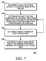
- FIG. 7 is a flowchart illustrating an example of techniques for determining a stability measure of the instrumented walker of FIGS. 1-3 .
- FIG. 1 is a block diagram of an instrumented mobility assistance system 100 .
- a walker 102 is illustrated as an example of a mobility assistance device.
- the walker 102 includes a frame 104 and wheels 106 .
- the walker 102 provides support and balance to a user (not illustrated) who grasps handles 108 of the walker 102 .
- a mobility and independence of the user may be enhanced.
- sensors 110 are disposed within, coupled to, or are otherwise associated with, the handles 108 , as one example of possible deployment on the frame 104 .
- the sensors 110 may include force and/or moment sensors.
- the sensors 110 act as transducers that are operable to translate information regarding an action of the user with respect to the walker 102 into an electrical signal(s) that is received at an instrumented walker system 112 .
- the instrumented walker system 112 analyzes the signals from the sensors 110 to characterize a use of the walker 102 by the user. In this way, the instrumented walker system 112 may characterize the use of the walker 102 , so as, for example, to determine or improve an effectiveness of the walker 102 with respect to the particular user, or with respect to all users. In other examples, the system 112 may be used to assist in monitoring, diagnosing, treating, or rehabilitating the user.
- the sensors 110 include force and/or moment sensors.
- the sensors 110 may include load cells that are operable to convert a force and/or weight of the user into an electrical signal for input into the system 112 .
- load cells may include, for example, a strain gage that is operable to change an internal resistance when stressed, in proportion to the stress. A corresponding electrical signal may be derived from this phenomenon, and may then be amplified, filtered, or otherwise manipulated for analysis.
- Such load cells or other types of the sensors 110 may thus be used to determine force components exerted on the handles 108 , and/or on the walker 102 as a whole, by the user. As the user moves with the assistance of the walker 102 , such force components may be exerted in any of the x, y, or z directions illustrated by the coordinate system of FIG. 1 .
- the sensors 110 may be used to determine moment measurements, which generally refer to a product of a quantity (e.g., a force) and a distance (or some power of the distance) to some point associated with that quantity.
- a quantity e.g., a force
- a distance or some power of the distance
- torque refers to the moment of force, so that, for example, if a force exerted by the user tends to rotate one of the handles 108 about some point, then the moment, or turning effect, is the product of the force and the distance from the point to the direction of the force.
- forces exerted by the user may create, for example, moments of force about the handles 108 (or, more generally, about any of the x, y, or z axes), which may be detected by the sensors 110 .
- the instrumented walker system 112 receives resulting signals from the sensors 110 , and, if necessary, amplifies and/or filters the signals at a filter 114 .
- a data acquisition system 116 then collects the (possibly filtered) data, which may include measurements over time of forces and moments with respect to any of the x, y, and z axes, and from either or both of the sensors 110 on the handles 108 .
- This sensor data may be stored in a memory 118 , and/or may be provided to a walker use analyzer 120 .
- the walker use analyzer 120 analyzes the sensor data in order to characterize a use of the walker 102 by the user. That is, as described in more detail below, the walker use analyzer 120 may characterize, for example, actions of the particular user, actions of general users or classes of users, a reaction of the walker 102 to the user(s) in question, or a reaction of the user and/or the walker 102 in specific contexts (e.g., sharp turns). The resulting use data may then be stored in a memory 122 .
- the walker use analyzer 120 inputs the sensor data into a gait analysis system 124 .
- the gait analysis system 124 is operable to determine, as discussed in more detail below, characteristics of a gait of the user, including, for example, a step count of the user and/or pace information.
- the sensor data may be received at a stability analysis system 126 , which is operable to determine a stability of the walker 102 .
- stability may be characterized in a number of different manners, and may be useful, for example, in determining a tip-over point of the walker 102 , perhaps with respect to the particular user, or more generally, or with respect to a particular terrain or usage experienced by the walker 102 .
- sensors 128 are illustrated in conjunction with the wheels 106 , and may include, for example, velocity and/or distance sensors.
- the sensors 128 may include odometers that are operable to measure a distance traveled by the user with the walker 102 .
- the sensors 128 may be in communication with the system 112 , data from the sensors 128 may be used to determine additional information regarding a use of the walker 102 by the user.
- the gait analysis system 124 may use the sensor data (including data from the sensors 110 and the sensors 128 ) to determine an average or instantaneous velocity of the user, as well as a step length and/or stride length of the user.
- wheeled walkers may easily be augmented with simple and relatively low-cost instrumentation technologies to provide a wide range of functionality and gait characteristics.
- this information may be used for maximizing user stability, determining control actions in controlled walkers (discussed in more detail below), and various other advantages that benefit users of the walker 102 .
- the system 100 allows walker use information to be obtained, stored, and analyzed in situ, in every-day environments experienced by walkers and their users.
- user and/or walker assessments may be more meaningful and useful.
- accurate and timely monitoring of the walker and/or user may be performed, in order, for example, to ensure a safety of the user or to monitor efficacy of medical interventions, such rehabilitation intervention, to enhance their benefit to the user.
- longitudinal assessment of functionality of the user may be used to provide clinicians with continuous measures of the user's functional ability and activity levels, and may hence help evaluate the user's health over a long period of time.
- functional assessment in the user's natural environment e.g., outside a clinic or gait lab, may be useful for monitoring the effectiveness of therapeutic interventions, including surgeries, drug therapy, or physical therapy, over extended periods of time.
- data may be collected over a period of time, for use in performing a trend analysis. For example, if data streams regarding step count, pace, timing of gait phases, instantaneous or average walking velocity, step length, stride length, or stability are collected over time, then trend analysis on one or more of these types of data, or in combinations thereof, may be informative to clinicians on the efficacy, or lack thereof, of interventions such as physical exercise or therapy, walking, rehabilitation, or medication. Additionally, for example, if data streams regarding any of the gait characteristics collected by the device longitudinally are collected over time, then trend analysis may demonstrate a sudden or abrupt change in one or more of these types of data, or in combinations thereof.
- Such a trend change may demonstrate, by itself, meaningful information related to a condition of the user, including, for example, a possible onset of a particular disease or condition, or a development of a disease or condition to acute status.
- trend analysis may indicate a sudden failure of a joint or bone of the user.
- use of the trend analysis information may be used in conjunction with other types of analyses in order to monitor or evaluate the user and/or the walker.
- the instrumented walker system 112 is illustrated as being on-board the walker 102 .
- the system 112 may be implemented in whole or in part apart from the walker 102 .
- data acquisition may occur at the walker 102 , and then may be stored (for later downloading) or transmitted for subsequent processing.
- sensor data may be transmitted directly from the sensors 110 and/or 128 to a remote version of the system 112 .
- the sensor data 118 may be stored locally to the walker 112 throughout some period of time, and thereafter may be connected to a computer for downloading over a wired or wireless connection including, by way of example and not limitation, Radio Frequency, Bluetooth, Infrared, optical communications, or other communications techniques.
- the sensor data 118 may be collected and transmitted to a portable computing device (e.g., a personal digital assistant (PDA)) of the user, at which other components of the system 112 may be implemented.
- PDA personal digital assistant
- the sensors 110 are disposed only on or in the handles 108 of the walker 102 . As a result, it is not necessary to dispose other sensors or information-tracking devices on a person of the user. Nonetheless, in some implementations, additional use information may be detected or determined based on sensors that are disposed on a person or clothing of the user.
- the sensors 110 need not be disposed in association with the handles 108 , and may be disposed in association with other portions of the walker 102 , including, for example, in association with the frame 104 and/or the wheels 106 , or in association with some combination of the handles 108 (or just one of the handles 108 ), the frame 104 , and the wheel(s) 106 .
- the sensors 110 are described as force/moment sensors, e.g., load cells, but it should be understood that various types of these sensors, and other sensors, not specifically mentioned here, also may be used.
- other sensor types that may be used include piezoelectric films, capacitive force sensors, or pressure sensors.
- FIG. 2 is a block diagram of the instrumented walker system 112 of FIG. 1 .
- force/moment sensor(s) 202 are specific examples of the sensors 110 described above. Accordingly, force and/or moment data from the sensors 202 is received at the filter 114 .
- a maximally flat response Infinite Impulse Response (IIR) low-pass filtering algorithm with a cut-off frequency of 3 Hz may be used in the data processing.
- IIR Infinite Impulse Response
- a non-causal bi-directional filter may be used in order to eliminate the phase shift caused by filtering.
- Such a filter may perform zero-phase shift digital filtering by processing the input data in both the forward and reverse directions.
- a causal filter with minimal phase shift may be used, or a causal filter with a linear phase response with a minimal order necessary to guarantee a desired on-line processing speed may be used.
- FIR filters Finite Impulse Response (FIR) filters or Butterworth IIR filter may be used.
- a magnitude response of the Butterworth IIR filter may be designed to be flat, and the phase response may be designed to be approximately linear in the pass-band.
- a high order Butterworth filter may be implemented for on-line gait detection.
- a minimum phase shift Butterworth IIR filter for on-line gait characterization also may be used.
- the force/moment sensor data may be analyzed, and characteristics of the data may be correlated with aspects of the user's motion.
- forces and moments recorded from the handle(s) 108 may include cyclic or quasi-cyclic changes reflecting a gait cycle of the user, and, from such changes, gait characteristic(s) may be determined.
- a peak (or valley) of a particular force or moment component(s) may be associated with a gait characteristic of the user, and, in particular, may be associated with a contact attribute associated with a contact of the user with a (e.g., ground) surface that is supporting the user and the walker 102 .
- a peak detection algorithm 204 may be implemented to determine such peaks, and these peaks may be correlated with contact attributes, such as, for example, an initial foot contact of the user with the ground surface, or a foot-off (i.e., dis-engagement of contact) of the user from the ground surface.
- Initial foot contact may include a heel-strike, or a toe-strike, or, in the case of a flat-footed user, may include a middle, majority, or entirety of the user's foot contacting the surface.
- foot-off events may include a toe-off, heel-off, or middle/entire foot-off from the ground surface.
- contact attribute is intended to include any engaging, maintaining, or dis-engaging of contact of the user, or a portion of the user, or a prosthesis of the user, with the supporting surface.
- the determination of the contact attributes allow for determination of what are termed herein as “basic” gait characteristics, and which include, for example, step count and/or pace information.
- Timing information from a timer 208 may be used in conjunction with the peak detection algorithm 204 to determine the basic gait characteristics 206 , such as pace (or number of steps per minute).
- the advanced gait characteristic determination 212 may include, for example, a determination of an instantaneous or average walking velocity of the user, a step length of the user, or a stride length of the user.
- a balance and stability determination 214 may be made.
- forces and moments applied to the walker 102 in the vertical direction and measured at the handles 108 may be used to measure ground reaction forces at the wheels 106 , using standard rigid body transformations, such as, for example, Walker's rigid body model.
- the ground reaction forces may be used to assess an index of stability of the walker/user system, throughout a plurality of gait phases and navigational modes. In this way, for example, a tip-over point or propensity of the walker 102 may be determined, and a safety and mobility of the user may be judged and may consequently be enhanced.
- local storage 216 is used to store the sensor data and/or gait and stability determinations. Contents of the local storage 216 may then be transferred to a remote storage and archiving memory 218 , for performance of a longitudinal data analysis 220 .
- FIG. 3 is a flowchart 300 illustrating example operations of the systems of FIGS. 1 and 2 .
- timing information is determined ( 302 ) to assist in the analysis of the use of the walker 102 .
- the time 208 of FIG. 2 may be continually running, or may be initiated when data is to be collected, in order to provide reference points for calculations of the quantities discussed below.
- Force and/or moment signals are received from the sensor signals 110 ( 304 ).
- forces and moments applied to the handle(s) 108 are measured via two commercially-available 6-degree of freedom (DoF) load cells.
- DoF 6-degree of freedom
- sensors may be used to provide the load/moment transfers between the walker 102 and the user.
- velocity/distance and/or other information may be received from the additional sensors 128 ( 306 ).
- Information regarding the gait of the user may be contained in all of the force moment components detected by the sensors 110 to one degree or another. In some implementations, this gait information is derived primarily or exclusively from the moment resulting from the user pushing down on the handle(s) 108 . In this way, a single axis sensor on each of the handles 108 may be sufficient to measure gait-related signal variations, such as, for example, the gait-related signal variations discussed below.
- peaks in the sensor signals from sensors 110 are examples of such gait-related signal variations, and, in particular, may be correlated with contact attributes related to a contact of the user with an underlying ground surface during normal use of the walker 102 .
- contact attributes refer to contact between a foot (or other feature, e.g., prosthesis) of the user and the underlying surface
- the contact attributes may include (and be referred to as) foot contact attributes or surface contact attributes.
- foot contact attributes may be determined ( 308 ).
- One example of determining foot contact attributes include determining foot initial contacts ( 310 ), e.g., heel strikes corresponding to an initial contacting of the user's foot with the ground during a stride.
- a second example includes determining foot-off instances ( 312 ), such as toe-off instances corresponding to a final contacting of the user's foot with the ground during a stride.
- a correlation may exist both between forces in the direction normal to the ground, F Z , and a corresponding moment around the (x) axis that is parallel to the ground and perpendicular to the direction of travel, i.e., the M X moment (or between other detected forces or moments). That is, peaks in either of the two signals F Z and M X may be shown to coincide with the heel strike instance(s).
- FIGS. 4A and 4B illustrate graphs showing a correlation between sensor signal peaks and heel strike instances.
- FIG. 4A illustrates a graph of the moment M X signal 402 for a left foot of the user.
- the signal 402 is illustrated against a reference signal 404 that illustrates a known occurrence of heel strike instances.
- the reference signal 404 illustrates motion data collected by a known vision-based motion capture system in which a motion model (walker/user) is computed in a conventional manner, using reflective markers attached to various points on the user's body and on the walker frame 104 , which are detected by six 120 Hz video cameras.
- This motion capture system is operable to create a 3-D motion model by using the positions in the (x-y-z) space of the particular real points (markers) placed on the user and on the walker frame 104 .
- the reference signal 404 illustrates a known representation of heel initial contacts as determined by the motion capture system, in which the heel initial contacts may be identified as valleys (e.g., valleys 406 and 408 ) in the vertical component of the trajectory traces of markers attached to the heel(s) of the user.
- valleys e.g., valleys 406 and 408
- points 410 and 412 illustrate heel initial contacts correlate with peaks of the M X moment signal 402 .
- the accuracy of these peaks in determining heel initial contacts may thus be determined by comparison against the known instances of heel initial contacts associated with valleys of the reference signal 404 , which, as shown by reference lines 414 , align favorably.
- the peak 412 of the left M X signal 402 has higher amplitude than the peak 410 , and coincides with heel initial contact of the corresponding (i.e., left) foot.
- the peak 410 of the left M X signal 402 is lower in amplitude than the peak 412 , and corresponds to heel initial contact of the opposite (i.e., right) foot. Accordingly, as may be seen in FIG. 4A , such higher and lower peaks alternate repetitively.
- FIG. 4B in which a right moment M X signal 416 is compared against a reference signal 418 , and illustrates peaks 420 and 422 corresponding to heel initial contacts. Again, the higher peak 422 coincides with the heel initial contact of the corresponding (i.e., right) foot, while the lower peak 420 coincides with the heel initial contact of the opposite (i.e., left) foot.
- This pattern reflects the lateral sway motion of the upper body of the user during ambulation, which can be modeled as an inverted pendulum, and the associated pattern of loading exerted on the walker frame.
- the load is transmitted through the walker's rigid frame and may be measured by ground reaction forces, as discussed in more detail, below.
- This pattern in the force-moment signals was exploited in developing a peak detection algorithm to identify right and left heel initial contacts from the right and left M X signals 416 and 402 , respectively.
- This peak detection algorithm is described in more detail below, with respect to FIG. 7 .
- peaks e.g., the peak 410 in M X signals (e.g., the left M X signal 402 ) coincide with heel initial contacts or valleys (e.g., the valley 406 ) obtained from the vertical signal(s) associated with the heel marker(s) of the referenced motion capture system.
- peaks marked by circles in FIGS. 4A and 4B e.g., the peaks 410 and 412
- valleys in the corresponding heel marker signal 404 as shown.
- Peaks e.g., a peak 424
- valleys e.g., a valley 426
- the determining of foot-off instances ( 312 ) may be illustrated by the example of FIGS. 5A and 5B , in which graphs illustrating correlations between the sensor signals 110 and the foot-off instances.
- FIG. 5A a correlation exists between the forward propulsion forces applied by the user, F Y (represented by a signal 502 ), and the toe-off event from the toe markers data captured by the reference motion capture system (represented by a reference signal 504 ).
- F Y represented by a signal 502
- toe-off event from the toe markers data captured by the reference motion capture system represented by a reference signal 504 .
- toe-off events may coincide with the start of an appreciable increase in the forward pushing force on the handle corresponding to the foot lifting off. Similar comments may apply to a force F Y signal 506 for the right foot, with respect to a right reference signal 508 .
- toe-off times may be estimated using a 60% rule, based on the detected heel strike events discussed above. For example, two successive heel strikes, measured for the same foot, may be used to compute the stride time (i.e., the duration of the gait cycle) of the user. Using a known normalized gait diagram, an estimate of the toe-off event may be obtained by adding 60% of the stride time to the time of the first detected heel contact. By repeating this process, a good estimate of all subsequent toe-off events may be obtained.
- FIGS. 5A and 5B graphically presents the results of toe-off estimation using the 60% estimation rule mentioned above, illustrated at reference points 510 and 512 .
- the 60% rule of the gait for toe-off estimation may be particularly useful for a normal gait of able-bodied subjects on level grounds. However, for patient populations with abnormal gait pathologies, or for inclined ramps, this value may not be applicable. Nonetheless, the estimation method may be adapted, by changing the percentage value, to cater for these situations. Additionally, a combination of the estimation rule and the above described valley detection algorithm may be used to detect foot-off more accurately in user's with gait abnormalities or locomotor disabilities.
- the determined foot contact attributes may be used to determine basic gait characteristics ( 314 ). Examples include pace/stride time/gait cycle, right and left single support phases, double support phases, and step count. Calculation of these quantities may be performed according to known methods, once the timing information and foot contact attributes are determined.
- a portion of the gait cycle that the user is currently in may be determined, and, therefore, appropriate control actions may be taken with respect to, for example, a control system that may be in place for controlling the walker 102 .
- a control system may enable, for example, a human/machine shared-control system that assists users by increasing the safety and speed of their daily travel.
- on-line gait characteristics detection may be used to determine the double support phase of the gait, and/or to initiate the control at the beginning of the double support phase for maximum dynamic stability.
- a measure of confidence may be ascribed to the gait information, and utilized during a decision making process for the on-line control of the walker 102 in such systems.
- the reception of the additional sensor information may allow for computation of advanced gait characteristics ( 316 ).
- Such characteristics include, for example, an instantaneous or average walking velocity, a step length of the user, or a stride length of the user. These and other quantities may be calculated using known calculation techniques. Examples of additional sensors that may be used include incremental wheel encoders, tachometers, or odometers.
- the determined force and/or moment signals may be used to determine a stability index and/or ground reaction forces associated with an in situ use of the walker 102 ( 318 ). From these determinations, an in situ stability of the user may be determined ( 320 ).
- known rigid body models may be applied to the frame 104 of the walker 102 , in order to translate the forces/moments applied by the user at the handles 108 into a representation of a stability index of the walker.
- a stability index may be formulated for a particular walker over a plurality of navigational scenarios, such as, for example, during straight-line operation, during gradual or sharp turns of the walker 102 , or over uneven surfaces.
- a stability computation model may be determined, based on a force-angle stability measure associated with the forces and moments detected at the handles 108 by the sensors 110 .
- a force-angle stability measure may be useful in measuring a stability of the walker 102 , due to a sensitivity of the measure with respect to angular loads (e.g., external forces and moments applied by the user).
- the measure may be used to determine an on-line, essentially instantaneous, stability margin during navigation with the walker 102 . Examples of determinations of stability measures are discussed in more detail below with respect to FIG. 7 .
- the instrumented walker 102 may be used to assist in clinical gait analysis ( 322 ).
- the walker 102 and associated system 112 may be used to store or archive the various gait characteristics, for future analysis thereof.
- gait analyses may be performed longitudinally “in the field,” where data may be most meaningful to the use and enjoyment of the user with respect to the walker 102 .
- Remote monitoring of the user may be performed, in order, for example, to provide care at a distance for the user, including diagnosis or re-habilitation.
- FIG. 6 is a flowchart 600 illustrating an example of the peak detection algorithm described in conjunction with FIGS. 2-5 , that may be used to determine heel strike instances.
- data from the right and left M X signals are analyzed to estimate an approximate time of each heel initial contact ( 602 ).
- the peak detection algorithm may be applied to a signal representing the summation of the right and left moment signals around the X axis (i.e., M x,left +M x,right ). In these cases, peaks corresponding to heel initial contacts may be enhanced because they are present in each of the two signals, unlike spurious peaks, which could be due to noise.
- the second step of the algorithm detects the actual timing of the heel initial contacts by analyzing the signal M x,left and M x,right independently.
- the estimated heel initial contact time is used to establish a relatively narrow time window (shown as a window 428 in FIG. 4 ) centered at the estimated heel initial contact times ( 604 ).
- a size of the window 428 may be determined by an optimizing algorithm on data from randomly selected subjects, where such an optimization may be based on selecting a window width that does not miss any heel initial contact in any trial performed by the subject(s). Accordingly, a minimum window width for all subjects may be selected such that an error between the time of heel initial contacts detected by the peak detection algorithm and the heel initial contact times provided by human detection on data from the motion capture system is minimized.
- the peak detection algorithm analyzes the signal in these windows to compute the accurate heel initial contact instances ( 606 ).
- This window method allows accurate identification of heel initial contacts (i.e. minimizes the absolute error between actual heel initial contacts and peaks identified in the moment signal), but may result in missing some peaks in each signal.
- the left and right moment signals M X may then be analyzed to associate the detected peak with the right or left heel initial contact ( 608 ).
- the peak detection algorithm may scan the M X data recorded for an entire trial in order to find a highest peak. Once this peak is detected, the algorithm may iteratively search for remaining peaks (after skipping a portion of the data that reflect a pre-determined dead-time, in order to avoid a detection of false peaks in the undulating M X signal that do not coincide with heel initial contacts).
- the algorithm stops when the amplitude of the current peak in sum of moments (M x,left +M x,right ) signal falls under some threshold, such as, for example, a threshold of 10 lb-in.
- This technique also may be used alone, as an off-line technique for analyzing sensors signals collected at the system 112 and downloaded for later analysis.
- peak detection algorithms or modification of the above-described algorithm, also may be used.
- a peak detection algorithm may be used in which a step lengths history (computed from previous heel initial contacts instances) is used to adapt the width of the window for each subject and for each estimated initial contact times.
- a similar data history based approach could be adopted to adapt the toe-off estimation method.
- the history-based peak detection and toe-off estimation algorithms may allow the adaptation of the method to cater for abnormal gait pathologies and locomotion disabilities.
- This increase in error may be expected, since the forces and moments exerted on the handles 108 include a component reflecting the user's desire to change the direction of the walker 102 , in addition to a component reflecting the user's increased need for support while performing a turn.
- gait characterization is limited to data collected during straight line segments (e.g., through tracking the orientation of the steering wheel using an encoder), the errors may be reduced, as may be a standard deviation of the errors.
- An accuracy of the heel initial contact detection algorithm(s) described above may be established on a step-by-step basis, through comparison to the count of steps detected by a human observer inspecting the heel marker signals from the motion capture system. For example, heel initial contacts detected by the algorithm and observed on the heel marker signals within the same step time window may be scored as a hit or a true positive. If the algorithm did not report an observed heel initial contact within a step time window of the motion capture system, a miss or a false negative may be determined. Heel initial contacts detected by the algorithm, but not observed on the motion capture system, may be scored as a false positive detection. Finally, if neither the algorithm nor the motion capture system reports a heel initial contact, a true negative may be recorded.
- the algorithm may be shown to have a high sensitivity and specificity, where the term sensitivity probabilistically measures the algorithm's ability to correctly detect an observed step (i.e., true positives), whereas specificity characterizes the algorithm's ability to identify true negatives correctly. Heel initial contacts of left and right foot from forces-moments exerted on walker handles 108 may be determined with 97% sensitivity and 98% specificity (with a narrow 95% Confidence Interval of ⁇ 1%).
- FIG. 7 is a flowchart 700 illustrating an example of techniques for determining a stability measure of the instrumented walker 102 .
- a force-angle stability measure considers a resultant force acting at a center of mass of the walker 102 , determined from the sensor signals ( 702 ).
- An angle that the component of the resultant force about a tip-over axis of the walker makes with a vector normal to a corresponding tip-over axis also may be computed ( 704 ).
- the three axes (each connecting two of the walker's three ground contact points) may be considered possible candidates to be a tip-over axis.
- the resultant force on the walker's center of mass may be calculated by performing appropriate transformations on the measured external forces applied by the user and the gravitational load of the walker 102 .
- the angular loads applied by the user also may be converted into an equivalent force couple for each tip-over axis.
- the overall force-angle stability measure of the walker 102 may then be calculated as the stability margin of the tip-over axis that has the minimum value of ⁇ associated therewith ( 708 ).
- a magnitude of a stability margin indicates a degree of stability of the system as a whole.
- higher positive values of a generally indicate a batter stability condition of the walker 102 .
- the walker 102 may be considered to be under critical stability and be about to tip-over, whereas a tip-over may be considered to be in progress when a goes negative.
- stability measures may be calculated instantaneously to evaluate a degree of stability during navigation.
- the continuous tracking of the stability margin also informs a control system of a stability trend over a period of time. For example, a scenario in which a stability margin continuously decreases at a steep slope for a period of time (e.g., approximately half a second) may indicate the proximity of a probable tip-over.
- ground reaction forces associated with the walker 102 also may be analyzed to determine a stability index, and, thereby potential tip-over points. For example, if a ground reaction force is determined for each contact point of the walker 102 with the underlying ground surface using a standard rigid body model describing the frame, then the contact point with the minimum ground reaction force may be used to construct a stability index, on the assumption that this contact point would define a most-probable tip-over point.
- a corresponding user stability measure associated with the user may be inferred.
- a given user may utilize the walker 102 for assistance in weight support, balance, or some combination thereof.
- a characterization of the stability of that user may be obtained. For example, a first user may have very good balance, but may need the walker 102 because the user's legs cannot support a full weight of the user. Such a user may have a high stability rating.
- a second user may have strong leg musculature, but may have an inner ear or other problem that leads to dizziness. Such a user may have a low stability rating.
- appropriate corrective action may be taken, either with respect to the type or implementation of the walker 102 , or with respect to a diagnosis and treatment of the user in question.
- the present description describes a device and method that passively assesses basic walker-assisted gait characteristics, including heel strikes and toe-off events, as well as stride time, double support, and right & left single support phases, using only force-moment measurements from the walker's handles.
- Additional gait characteristics such as, for example, walking velocity, step length, stride length, and walker-user system stability also may be passively derived through the utilization of additional sensors.
- the application of the instrumented walker and the described methods may be extended to longitudinal, outside the lab, gait assessment and monitoring.
- problems associated with routine clinical use of gait analysis e.g., the manner in which gait laboratories are organized, tests are performed, and reports are generated, as well as the length of time and costs required for performing and interpreting tests
- gait analysis e.g., the manner in which gait laboratories are organized, tests are performed, and reports are generated, as well as the length of time and costs required for performing and interpreting tests
- Implementations also may be extended to other walker types, including, for example, back support walkers used by cerebral palsy patients and push-carts (such as strollers, shopping carts, and other devices used to enhance a mobility of a user, including able-bodied users requiring assistance to mobilize a weighted object for transport).
- Other types of mobility-assistance devices that are contemplated include, for example, two-wheeled slide walkers, three-wheeled walkers, four wheeled walkers, or any push-cart that requires the user to provide propulsion.
- the walker/cart may have active steering control, or a free wheeling castor, or a stepper motor (e.g., to control the steering direction of the front steering wheel).
- Such navigational scenarios include, for example, walking in a straight line, or turning right and left at two different angles on each side.
- Implementations may be implemented with a wide variety of special-purpose or general-purpose computing devices, systems, and configurations. Implementations may be implemented in computer-executable instructions designed for execution by a computing device. Implementations may be implemented as any combination of hardware, software, of firmware, as would be apparent.
Priority Applications (1)
| Application Number | Priority Date | Filing Date | Title |
|---|---|---|---|
| US11/650,361 US7826983B2 (en) | 2004-07-07 | 2007-01-05 | Instrumented mobility assistance device |
Applications Claiming Priority (3)
| Application Number | Priority Date | Filing Date | Title |
|---|---|---|---|
| US58610704P | 2004-07-07 | 2004-07-07 | |
| PCT/US2005/024072 WO2006014533A2 (en) | 2004-07-07 | 2005-07-07 | Instrumented mobility assistance device |
| US11/650,361 US7826983B2 (en) | 2004-07-07 | 2007-01-05 | Instrumented mobility assistance device |
Related Parent Applications (1)
| Application Number | Title | Priority Date | Filing Date |
|---|---|---|---|
| PCT/US2005/024072 Continuation WO2006014533A2 (en) | 2004-07-07 | 2005-07-07 | Instrumented mobility assistance device |
Publications (2)
| Publication Number | Publication Date |
|---|---|
| US20070233403A1 US20070233403A1 (en) | 2007-10-04 |
| US7826983B2 true US7826983B2 (en) | 2010-11-02 |
Family
ID=35787642
Family Applications (1)
| Application Number | Title | Priority Date | Filing Date |
|---|---|---|---|
| US11/650,361 Expired - Fee Related US7826983B2 (en) | 2004-07-07 | 2007-01-05 | Instrumented mobility assistance device |
Country Status (3)
| Country | Link |
|---|---|
| US (1) | US7826983B2 (de) |
| EP (1) | EP1774300A4 (de) |
| WO (1) | WO2006014533A2 (de) |
Cited By (16)
| Publication number | Priority date | Publication date | Assignee | Title |
|---|---|---|---|---|
| US20100100013A1 (en) * | 2006-05-01 | 2010-04-22 | De Novo Technologies, Inc. | Products and Methods for Motor Performance Improvement in Patients with Neurodegenerative Disease |
| US20110118898A1 (en) * | 2009-11-17 | 2011-05-19 | National Taiwan University | Rehabilitation Device |
| US7963294B1 (en) * | 2010-10-10 | 2011-06-21 | Trout William G | Assistive walker apparatus |
| US20110166753A1 (en) * | 2010-01-07 | 2011-07-07 | Chung-Huang Yu | Walking assistance device with detection members |
| US20110212810A1 (en) * | 2010-03-01 | 2011-09-01 | University Of Maryland | Balance training system |
| US20140190536A1 (en) * | 2012-12-04 | 2014-07-10 | Scott & White Healthcare | Systems and Methods for Assisted Ambulation |
| US20160058649A1 (en) * | 2014-09-01 | 2016-03-03 | National Taiwan University | Rehabilitation device with pace pattern projecting function and seat structure and control method thereof |
| US9360343B2 (en) | 2012-06-25 | 2016-06-07 | International Business Machines Corporation | Monitoring use of a single arm walking aid |
| US20160262661A1 (en) * | 2015-03-11 | 2016-09-15 | Vanderbilt University | Walking aid and system and method of gait monitoring |
| US9526437B2 (en) | 2012-11-21 | 2016-12-27 | i4c Innovations Inc. | Animal health and wellness monitoring using UWB radar |
| US9808391B1 (en) * | 2015-07-16 | 2017-11-07 | Lorie Zacharias-Verdi | Walker safety device |
| US10149617B2 (en) | 2013-03-15 | 2018-12-11 | i4c Innovations Inc. | Multiple sensors for monitoring health and wellness of an animal |
| US10267648B2 (en) | 2016-02-04 | 2019-04-23 | Jeffrey Turitz | System for measuring distances traveled by a mobility assistance device |
| US10898397B2 (en) | 2016-02-04 | 2021-01-26 | Jeffrey Turitz | System for measuring distances traveled by a mobility assistance device |
| US20210298986A1 (en) * | 2020-03-30 | 2021-09-30 | Toyota Jidosha Kabushiki Kaisha | Stick, method of controlling stick, and program |
| US20220096311A1 (en) * | 2020-09-28 | 2022-03-31 | Wistron Corporation | Active rollator |
Families Citing this family (49)
| Publication number | Priority date | Publication date | Assignee | Title |
|---|---|---|---|---|
| WO2006014533A2 (en) | 2004-07-07 | 2006-02-09 | Home Guardian Llc | Instrumented mobility assistance device |
| US20060025836A1 (en) * | 2004-08-02 | 2006-02-02 | Van Gerpen Jay A | Device to alleviate freezing of gait in users with Parkinsonism |
| US8573612B1 (en) * | 2006-03-09 | 2013-11-05 | Clarkson University | Assistive ambulatory device |
| DE102006024019B4 (de) * | 2006-05-23 | 2009-10-15 | Boris Litver | Gehhilfewagen |
| US8652040B2 (en) | 2006-12-19 | 2014-02-18 | Valencell, Inc. | Telemetric apparatus for health and environmental monitoring |
| US8157730B2 (en) * | 2006-12-19 | 2012-04-17 | Valencell, Inc. | Physiological and environmental monitoring systems and methods |
| US7567874B2 (en) * | 2007-09-28 | 2009-07-28 | Intel Corporation | System and method for detecting furniture cruising frequency to monitor gait decline |
| US8251903B2 (en) | 2007-10-25 | 2012-08-28 | Valencell, Inc. | Noninvasive physiological analysis using excitation-sensor modules and related devices and methods |
| US8788002B2 (en) | 2009-02-25 | 2014-07-22 | Valencell, Inc. | Light-guiding devices and monitoring devices incorporating same |
| EP2400884B1 (de) | 2009-02-25 | 2018-03-07 | Valencell, Inc. | Lichtgeleitete vorrichtungen und überwachungsvorrichtungen damit |
| US9750462B2 (en) | 2009-02-25 | 2017-09-05 | Valencell, Inc. | Monitoring apparatus and methods for measuring physiological and/or environmental conditions |
| FR2967570B1 (fr) * | 2010-11-18 | 2013-08-09 | Safe Step And Walk Movement | Dispositif d'aide a la marche par soutenement |
| US8888701B2 (en) | 2011-01-27 | 2014-11-18 | Valencell, Inc. | Apparatus and methods for monitoring physiological data during environmental interference |
| FR2971419B1 (fr) * | 2011-02-10 | 2014-05-09 | Rise Ba | Dispositif de reeducation ambulatoire autonome |
| WO2013016007A2 (en) | 2011-07-25 | 2013-01-31 | Valencell, Inc. | Apparatus and methods for estimating time-state physiological parameters |
| WO2013019494A2 (en) | 2011-08-02 | 2013-02-07 | Valencell, Inc. | Systems and methods for variable filter adjustment by heart rate metric feedback |
| EP2931125A4 (de) | 2013-01-28 | 2015-11-11 | Valencell Inc | Vorrichtungen zur überwachung physiologischer funktionen mit von körperbewegungen abgekoppelten sensorelementen |
| WO2014127417A1 (en) * | 2013-02-20 | 2014-08-28 | Terence Vardy | The collection of medical data |
| KR102207770B1 (ko) | 2013-08-05 | 2021-01-26 | 트위스트 바이오사이언스 코포레이션 | 드 노보 합성된 유전자 라이브러리 |
| CA2963072A1 (en) | 2013-10-29 | 2015-05-07 | Milbat - Giving Quality To Life | Walker-assist device |
| US20160029898A1 (en) | 2014-07-30 | 2016-02-04 | Valencell, Inc. | Physiological Monitoring Devices and Methods Using Optical Sensors |
| EP3199100A1 (de) | 2014-08-06 | 2017-08-02 | Valencell, Inc. | Ohrhörer mit einem physiologischen informationen sensormodul |
| US9794653B2 (en) | 2014-09-27 | 2017-10-17 | Valencell, Inc. | Methods and apparatus for improving signal quality in wearable biometric monitoring devices |
| US20170352288A1 (en) * | 2014-12-19 | 2017-12-07 | Koninklijke Philips N.V. | Method and system for physical training and rehabilitation |
| WO2016172377A1 (en) | 2015-04-21 | 2016-10-27 | Twist Bioscience Corporation | Devices and methods for oligonucleic acid library synthesis |
| GB2538953B (en) * | 2015-05-28 | 2021-02-17 | Meiban Int Pte Ltd | Smart elderly walker |
| US10945618B2 (en) | 2015-10-23 | 2021-03-16 | Valencell, Inc. | Physiological monitoring devices and methods for noise reduction in physiological signals based on subject activity type |
| WO2017070463A1 (en) | 2015-10-23 | 2017-04-27 | Valencell, Inc. | Physiological monitoring devices and methods that identify subject activity type |
| WO2017095958A1 (en) | 2015-12-01 | 2017-06-08 | Twist Bioscience Corporation | Functionalized surfaces and preparation thereof |
| TWI634885B (zh) * | 2016-01-06 | 2018-09-11 | 國立交通大學 | 用於控制行走輔具的方法 |
| JP6945176B2 (ja) * | 2016-06-29 | 2021-10-06 | パナソニックIpマネジメント株式会社 | 歩行支援ロボット及び歩行支援方法 |
| WO2018003910A1 (ja) * | 2016-07-01 | 2018-01-04 | 日本電気株式会社 | 歩行状態判定装置、歩行状態判定システム、歩行状態判定方法及び記憶媒体 |
| WO2018009736A1 (en) | 2016-07-08 | 2018-01-11 | Valencell, Inc. | Motion-dependent averaging for physiological metric estimating systems and methods |
| WO2018057526A2 (en) | 2016-09-21 | 2018-03-29 | Twist Bioscience Corporation | Nucleic acid based data storage |
| JP7169975B2 (ja) | 2016-12-16 | 2022-11-11 | ツイスト バイオサイエンス コーポレーション | 免疫シナプスの変異体ライブラリーおよびその合成 |
| GB2578844A (en) | 2017-06-12 | 2020-05-27 | Twist Bioscience Corp | Methods for seamless nucleic acid assembly |
| GB2581620A (en) | 2017-09-11 | 2020-08-26 | Twist Bioscience Corp | GPCR binding proteins and synthesis thereof |
| US10894242B2 (en) | 2017-10-20 | 2021-01-19 | Twist Bioscience Corporation | Heated nanowells for polynucleotide synthesis |
| US10772788B2 (en) * | 2017-11-07 | 2020-09-15 | Jeffrey Kapec | Rollator |
| US11396314B2 (en) | 2018-03-28 | 2022-07-26 | The Board Of Trustees Of The University Of Alabama | Motorized robotic walker guided by an image processing system for human walking assistance |
| US20190358821A1 (en) * | 2018-05-25 | 2019-11-28 | Panasonic Corporation | Walking training robot |
| JP7075822B2 (ja) | 2018-06-04 | 2022-05-26 | パナソニックホールディングス株式会社 | マップ情報更新システム |
| US11564439B2 (en) * | 2018-08-07 | 2023-01-31 | Under Armour, Inc. | System and method for determining foot strike pattern |
| CN112996464A (zh) | 2018-09-14 | 2021-06-18 | 德奥罗设备公司 | 用于处理步行障碍的提示设备和方法 |
| US11071676B2 (en) | 2019-04-05 | 2021-07-27 | Protostar, Inc. | Collapsible wheeled walker with stability enhancing bracket apparatus and method |
| JP2020185063A (ja) * | 2019-05-10 | 2020-11-19 | 株式会社ジェイテクト | 配信システム |
| NL2023345B1 (en) * | 2019-06-19 | 2021-01-28 | Bobergo B V | Feedback system and method for providing feedback to walking aid users |
| KR102300574B1 (ko) * | 2019-07-10 | 2021-09-09 | 엘지전자 주식회사 | 사용자 신체 특성을 반영하여 파워 어시스트 모드로 이동하는 방법 및 이를 구현하는 카트로봇 |
| US20210236022A1 (en) * | 2020-02-04 | 2021-08-05 | Protostar, Inc., a Delaware Corporation | Smart Interpretive Wheeled Walker using Sensors and Artificial Intelligence for Precision Assisted Mobility Medicine Improving the Quality of Life of the Mobility Impaired |
Citations (23)
| Publication number | Priority date | Publication date | Assignee | Title |
|---|---|---|---|---|
| US4760850A (en) * | 1986-05-15 | 1988-08-02 | Wright State University | Method for balancing assistance |
| US5511571A (en) * | 1993-11-05 | 1996-04-30 | Adrezin; Ronald S. | Method and apparatus for gait measurement |
| US5794639A (en) * | 1995-10-31 | 1998-08-18 | Einbinder; Eli | Adjustably controllable walker |
| US5853219A (en) * | 1997-05-06 | 1998-12-29 | Santuccio; Kathleen M. | Safety walker assembly |
| US6183425B1 (en) * | 1995-10-13 | 2001-02-06 | The United States Of America As Represented By The Administrator Of The National Aeronautics And Space Administration | Method and apparatus for monitoring of daily activity in terms of ground reaction forces |
| US6298314B1 (en) * | 1997-10-02 | 2001-10-02 | Personal Electronic Devices, Inc. | Detecting the starting and stopping of movement of a person on foot |
| EP1260201A1 (de) | 2001-05-24 | 2002-11-27 | Argo Medical Technologies Ltd. | Vorrichtung zum Erzeugen einer Gehbewegung |
| US6493652B1 (en) * | 1997-10-02 | 2002-12-10 | Personal Electronic Devices, Inc. | Monitoring activity of a user in locomotion on foot |
| US6536544B1 (en) * | 1997-03-17 | 2003-03-25 | Hitachi, Ltd. | Walking aid apparatus |
| US6540039B1 (en) * | 1999-08-19 | 2003-04-01 | Massachusetts Institute Of Technology | Omnidirectional vehicle with offset wheel pairs |
| US6611789B1 (en) * | 1997-10-02 | 2003-08-26 | Personal Electric Devices, Inc. | Monitoring activity of a user in locomotion on foot |
| US6645126B1 (en) * | 2000-04-10 | 2003-11-11 | Biodex Medical Systems, Inc. | Patient rehabilitation aid that varies treadmill belt speed to match a user's own step cycle based on leg length or step length |
| US6644976B2 (en) * | 2001-09-10 | 2003-11-11 | Epoch Innovations Ltd | Apparatus, method and computer program product to produce or direct movements in synergic timed correlation with physiological activity |
| US6666796B1 (en) * | 1999-09-16 | 2003-12-23 | Aerovironment, Inc. | Walking assisting apparatus |
| US20040102723A1 (en) * | 2002-11-25 | 2004-05-27 | Horst Robert W. | Active muscle assistance device and method |
| US20050279551A1 (en) | 2004-06-21 | 2005-12-22 | Lopresti Edmund F | Power apparatus for wheelchairs |
| WO2006014533A2 (en) | 2004-07-07 | 2006-02-09 | Home Guardian Llc | Instrumented mobility assistance device |
| US7065408B2 (en) * | 2001-01-11 | 2006-06-20 | Herman Richard M | Method for restoring gait in individuals with chronic spinal cord injury |
| US20060195050A1 (en) * | 2003-04-03 | 2006-08-31 | University Of Virginia Patent Foundation | Method and system for the derivation of human gait characteristics and detecting falls passively from floor vibrations |
| US20060292533A1 (en) * | 2005-06-22 | 2006-12-28 | Selod Omar F | System and method for gait training |
| US7190141B1 (en) * | 2006-01-27 | 2007-03-13 | Villanova University | Exoskeletal device for rehabilitation |
| US20080114272A1 (en) * | 2000-03-29 | 2008-05-15 | Massachusetts Institute Of Technology | Control system for prosthetic knee |
| US7647196B2 (en) * | 2007-08-08 | 2010-01-12 | Dp Technologies, Inc. | Human activity monitoring device with distance calculation |
Family Cites Families (1)
| Publication number | Priority date | Publication date | Assignee | Title |
|---|---|---|---|---|
| US5551571A (en) | 1995-09-18 | 1996-09-03 | Vanguard International Semiconductor Corp. | Semiconductor wafer container |
-
2005
- 2005-07-07 WO PCT/US2005/024072 patent/WO2006014533A2/en not_active Application Discontinuation
- 2005-07-07 EP EP05769998A patent/EP1774300A4/de not_active Withdrawn
-
2007
- 2007-01-05 US US11/650,361 patent/US7826983B2/en not_active Expired - Fee Related
Patent Citations (24)
| Publication number | Priority date | Publication date | Assignee | Title |
|---|---|---|---|---|
| US4760850A (en) * | 1986-05-15 | 1988-08-02 | Wright State University | Method for balancing assistance |
| US5511571A (en) * | 1993-11-05 | 1996-04-30 | Adrezin; Ronald S. | Method and apparatus for gait measurement |
| US6183425B1 (en) * | 1995-10-13 | 2001-02-06 | The United States Of America As Represented By The Administrator Of The National Aeronautics And Space Administration | Method and apparatus for monitoring of daily activity in terms of ground reaction forces |
| US5794639A (en) * | 1995-10-31 | 1998-08-18 | Einbinder; Eli | Adjustably controllable walker |
| US6536544B1 (en) * | 1997-03-17 | 2003-03-25 | Hitachi, Ltd. | Walking aid apparatus |
| US5853219A (en) * | 1997-05-06 | 1998-12-29 | Santuccio; Kathleen M. | Safety walker assembly |
| US6611789B1 (en) * | 1997-10-02 | 2003-08-26 | Personal Electric Devices, Inc. | Monitoring activity of a user in locomotion on foot |
| US6298314B1 (en) * | 1997-10-02 | 2001-10-02 | Personal Electronic Devices, Inc. | Detecting the starting and stopping of movement of a person on foot |
| US6493652B1 (en) * | 1997-10-02 | 2002-12-10 | Personal Electronic Devices, Inc. | Monitoring activity of a user in locomotion on foot |
| US6540039B1 (en) * | 1999-08-19 | 2003-04-01 | Massachusetts Institute Of Technology | Omnidirectional vehicle with offset wheel pairs |
| US6666796B1 (en) * | 1999-09-16 | 2003-12-23 | Aerovironment, Inc. | Walking assisting apparatus |
| US20080114272A1 (en) * | 2000-03-29 | 2008-05-15 | Massachusetts Institute Of Technology | Control system for prosthetic knee |
| US6645126B1 (en) * | 2000-04-10 | 2003-11-11 | Biodex Medical Systems, Inc. | Patient rehabilitation aid that varies treadmill belt speed to match a user's own step cycle based on leg length or step length |
| US7065408B2 (en) * | 2001-01-11 | 2006-06-20 | Herman Richard M | Method for restoring gait in individuals with chronic spinal cord injury |
| EP1260201A1 (de) | 2001-05-24 | 2002-11-27 | Argo Medical Technologies Ltd. | Vorrichtung zum Erzeugen einer Gehbewegung |
| US6644976B2 (en) * | 2001-09-10 | 2003-11-11 | Epoch Innovations Ltd | Apparatus, method and computer program product to produce or direct movements in synergic timed correlation with physiological activity |
| US20040102723A1 (en) * | 2002-11-25 | 2004-05-27 | Horst Robert W. | Active muscle assistance device and method |
| US20060195050A1 (en) * | 2003-04-03 | 2006-08-31 | University Of Virginia Patent Foundation | Method and system for the derivation of human gait characteristics and detecting falls passively from floor vibrations |
| US20050279551A1 (en) | 2004-06-21 | 2005-12-22 | Lopresti Edmund F | Power apparatus for wheelchairs |
| WO2006014533A2 (en) | 2004-07-07 | 2006-02-09 | Home Guardian Llc | Instrumented mobility assistance device |
| US20070233403A1 (en) * | 2004-07-07 | 2007-10-04 | Majd Alwan | Instrumented mobility assistance device |
| US20060292533A1 (en) * | 2005-06-22 | 2006-12-28 | Selod Omar F | System and method for gait training |
| US7190141B1 (en) * | 2006-01-27 | 2007-03-13 | Villanova University | Exoskeletal device for rehabilitation |
| US7647196B2 (en) * | 2007-08-08 | 2010-01-12 | Dp Technologies, Inc. | Human activity monitoring device with distance calculation |
Non-Patent Citations (17)
| Title |
|---|
| "Number of Persons Using Assistive Technology by Age of Person and type of Device", National Center for Health Statistics, (1994), 4 pages. |
| Aminian, K et al., "Temporal feature estimation during walking using miniature accelerometers: an analysis of gait improvement after hip arthroplasty", Medical and Biological Engineering and Computing, vol. 37, No. 1, (Jan. 1999), pp. 686-691. |
| Bachschmidt, R A., et al., "Walker-assisted gait in rehabilitation: a study of biomechanics and instrumentation", IEEE Transactions on Neural Systems and Rehabilitation Engineering, vol. 9, issue 1, (Mar. 2001), pp. 96-105. |
| Chen, Chia-Ling et al., "Temporal stride and force analysis of cane-assisted gait in people with hemiplegic stroke", Archives of Physical Medicine and Rehabilitation, vol. 82, Issue 1, (Jan. 2001), pp. 43-48. |
| Fast, A et al., "The Instrumented Walker: Usage Patterns and Forces", Archives of Physical Medicine & Rehabilitation, vol. 76, issue 5, (May 1995), pp. 484-491. |
| Fay, Brain T., et al., "The science behind mobility devices for individuals with multiple sclerosis", Medical Engineering & Physics, vol. 24, issue 6, (Jul. 2002), pp. 375-383. |
| International Search Report for International Application No. PCT/US05/24072 (Apr. 28, 2006). |
| Karcnik, T et al., "Using motion analysis data for foot-floor contact detection", Medical and Biological Engineering and Computing, vol. 41, No. 5, (Sep. 2003), pp. 509-512. |
| Mansfield, Avril et al., "The use of accelerometry to detect heel contact events for use as a sensor in FES assisted walking", Medical Engineering & Physics, vol. 25, Issue 10, (Dec. 2003), pp. 879-885. |
| Pappas, I P., et al., "A reliable gait phase detection system", IEEE Transactions on Neural Systems and Rehabilitation Engineering, vol. 9, Issue 2, (Jun. 2001), pp. 113-125. |
| Pappas, I P., et al., "A reliable gyroscope-based gait-phase detection sensor embedded in a shoe insole", IEEE Sensors Journal, vol. 4, Issue 2, (Apr. 2004), pp. 268-274. |
| Sheldon, R S., "Quantification of human motion: gait analysis-benefits and limitations to its application to clinical problems", Journal of Biomechanics, vol. 37, Issue 12, (Dec. 2004), pp. 1869-1880. |
| Skelly, M M., et al., "Real-time gait event detection for paraplegic FES walking", IEEE Transactions on Neural Systems and Rehabilitation Engineering, vol. 9, Issue 1, (Mar. 2001), pp. 59-68. |
| Wasson, G et al., "Effective Shared Control in Cooperative Mobility Aids", In Proceedings of the Fourteenth international Florida Artificial intelligence Research Society Conference, (May 21-23, 2001), pp. 509-513. |
| Wasson, Glenn et al., "An Assistive Robotic Agent for Pedestrian Mobility", International Conference on Autonomous Agents, (2001), pp. 169-173. |
| Wasson, Glenn et al., "User Intent in a Shared Control Framework for Pedestrian Mobility Aids", IEEE International Conference on Intelligent Robots and Systems (IROS), (2003), 6 pages. |
| Wasson, Glenn et al., "User Intent in a Shared Control Framework for Pedestrian Mobility Aids", IEEE International Conference on Intelligent Robots and Systems (IROS), 2003, 6 pages. * |
Cited By (25)
| Publication number | Priority date | Publication date | Assignee | Title |
|---|---|---|---|---|
| US20100100013A1 (en) * | 2006-05-01 | 2010-04-22 | De Novo Technologies, Inc. | Products and Methods for Motor Performance Improvement in Patients with Neurodegenerative Disease |
| US8702567B2 (en) * | 2006-05-01 | 2014-04-22 | Nicholas S. Hu | Products and methods for motor performance improvement in patients with neurodegenerative disease |
| US20110118898A1 (en) * | 2009-11-17 | 2011-05-19 | National Taiwan University | Rehabilitation Device |
| US8500143B2 (en) * | 2010-01-07 | 2013-08-06 | National Yang-Ming University | Walking assistance device with detection members |
| US20110166753A1 (en) * | 2010-01-07 | 2011-07-07 | Chung-Huang Yu | Walking assistance device with detection members |
| US20110212810A1 (en) * | 2010-03-01 | 2011-09-01 | University Of Maryland | Balance training system |
| US8900165B2 (en) | 2010-03-01 | 2014-12-02 | University Of Maryland, College Park | Balance training system |
| US7963294B1 (en) * | 2010-10-10 | 2011-06-21 | Trout William G | Assistive walker apparatus |
| US9360343B2 (en) | 2012-06-25 | 2016-06-07 | International Business Machines Corporation | Monitoring use of a single arm walking aid |
| US9526437B2 (en) | 2012-11-21 | 2016-12-27 | i4c Innovations Inc. | Animal health and wellness monitoring using UWB radar |
| US11317608B2 (en) | 2012-11-21 | 2022-05-03 | i4c Innovations Inc. | Animal health and wellness monitoring using UWB radar |
| US10070627B2 (en) | 2012-11-21 | 2018-09-11 | i4c Innovations Inc. | Animal health and wellness monitoring using UWB radar |
| US20140190536A1 (en) * | 2012-12-04 | 2014-07-10 | Scott & White Healthcare | Systems and Methods for Assisted Ambulation |
| US9180063B2 (en) * | 2012-12-04 | 2015-11-10 | Scott & White Healthcare (Swh) | Systems and methods for assisted ambulation |
| US10149617B2 (en) | 2013-03-15 | 2018-12-11 | i4c Innovations Inc. | Multiple sensors for monitoring health and wellness of an animal |
| US20160058649A1 (en) * | 2014-09-01 | 2016-03-03 | National Taiwan University | Rehabilitation device with pace pattern projecting function and seat structure and control method thereof |
| US9510992B2 (en) * | 2014-09-01 | 2016-12-06 | National Taiwan University | Rehabilitation device with pace pattern projecting function and seat structure and control method thereof |
| US20160262661A1 (en) * | 2015-03-11 | 2016-09-15 | Vanderbilt University | Walking aid and system and method of gait monitoring |
| US10799154B2 (en) * | 2015-03-11 | 2020-10-13 | Vanderbilt University | Walking aid and system and method of gait monitoring |
| US9808391B1 (en) * | 2015-07-16 | 2017-11-07 | Lorie Zacharias-Verdi | Walker safety device |
| US10267648B2 (en) | 2016-02-04 | 2019-04-23 | Jeffrey Turitz | System for measuring distances traveled by a mobility assistance device |
| US10898397B2 (en) | 2016-02-04 | 2021-01-26 | Jeffrey Turitz | System for measuring distances traveled by a mobility assistance device |
| US20210298986A1 (en) * | 2020-03-30 | 2021-09-30 | Toyota Jidosha Kabushiki Kaisha | Stick, method of controlling stick, and program |
| US20220096311A1 (en) * | 2020-09-28 | 2022-03-31 | Wistron Corporation | Active rollator |
| US11890256B2 (en) * | 2020-09-28 | 2024-02-06 | Wistron Corporation | Active rollator |
Also Published As
| Publication number | Publication date |
|---|---|
| US20070233403A1 (en) | 2007-10-04 |
| EP1774300A4 (de) | 2008-07-02 |
| EP1774300A2 (de) | 2007-04-18 |
| WO2006014533A2 (en) | 2006-02-09 |
| WO2006014533A3 (en) | 2006-06-29 |
Similar Documents
| Publication | Publication Date | Title |
|---|---|---|
| US7826983B2 (en) | Instrumented mobility assistance device | |
| Zhang et al. | Accurate ambulatory gait analysis in walking and running using machine learning models | |
| CN106815857B (zh) | 行动辅助机器人的姿态估测方法 | |
| Ding et al. | Gait event detection of a lower extremity exoskeleton robot by an intelligent IMU | |
| US9826806B2 (en) | Assistive support systems and devices for automatic feedback | |
| Qiu et al. | Using body-worn sensors for preliminary rehabilitation assessment in stroke victims with gait impairment | |
| US20120232430A1 (en) | Universal actigraphic device and method of use therefor | |
| Alwan et al. | Basic walker-assisted gait characteristics derived from forces and moments exerted on the walker's handles: results on normal subjects | |
| CN108577854A (zh) | 步态识别方法和步态辅助设备 | |
| Lee et al. | Detection of spatio-temporal gait parameters by using wearable motion sensors | |
| Wang et al. | Estimate spatial-temporal parameters of human gait using inertial sensors | |
| Culmer et al. | An instrumented walking aid to assess and retrain gait | |
| Postolache et al. | Smart walker solutions for physical rehabilitation | |
| Alahakone et al. | Smart wearable device for real time gait event detection during running | |
| Seylan et al. | Estimation of ground reaction forces using low-cost instrumented forearm crutches | |
| Alwan et al. | Passive derivation of basic walker-assisted gait characteristics from measured forces and moments | |
| TW201311214A (zh) | 視覺化imu步態偵測裝置及其分析方法 | |
| JP2008161227A (ja) | 歩行分析システム | |
| Dune et al. | Can smart rollators be used for gait monitoring and fall prevention? | |
| Abinaya et al. | An advanced gait monitoring system based on air pressure sensor embedded in a shoe | |
| US20230330835A1 (en) | System and process for estimation of gait phase for use with a wearable robot | |
| Jang et al. | Recognition of walking intention using multiple bio/kinesthetic sensors for lower limb exoskeletons | |
| Qiu et al. | Gaitsense: A potential assistance for physical rehabilitation by means of wearable sensors | |
| EP3838143A1 (de) | Mobilitätsvorrichtung zur überwachung und/oder rehabilitation der gehaktivität | |
| Bae et al. | Design of a mobile gait monitoring system |
Legal Events
| Date | Code | Title | Description |
|---|---|---|---|
| STCF | Information on status: patent grant |
Free format text: PATENTED CASE |
|
| AS | Assignment |
Owner name: ALWAN, MAJD, VIRGINIA Free format text: ASSIGNMENT OF ASSIGNORS INTEREST;ASSIGNOR:WELLAWARE SYSTEMS, INC. (P/K/A HOME GUARDIAN LLC);REEL/FRAME:025393/0145 Effective date: 20100930 Owner name: HOME GUARDIAN LLC (N/K/A WELLAWARE SYSTEMS, INC.), Free format text: ASSIGNMENT OF ASSIGNORS INTEREST;ASSIGNORS:ALWAN, MAJD;WASSON, GLENN;SHETH, PRADIP;AND OTHERS;REEL/FRAME:025393/0113 Effective date: 20060615 |
|
| FPAY | Fee payment |
Year of fee payment: 4 |
|
| SULP | Surcharge for late payment | ||
| AS | Assignment |
Owner name: WELLAWARE SYSTEMS, INC., VIRGINIA Free format text: CHANGE OF NAME;ASSIGNOR:HOME GUARDIAN, LLC;REEL/FRAME:034565/0126 Effective date: 20091016 |
|
| AS | Assignment |
Owner name: HEALTHSENSE, INC., MINNESOTA Free format text: ASSIGNMENT OF ASSIGNORS INTEREST;ASSIGNOR:WELLAWARE SYSTEMS, INC.;REEL/FRAME:034872/0602 Effective date: 20150202 |
|
| AS | Assignment |
Owner name: THE NORTHWESTERN MUTUAL LIFE INSURANCE COMPANY, AS Free format text: SECOND LIEN PATENT SECURITY AGREEMENT;ASSIGNOR:GREATCALL, INC.;REEL/FRAME:043360/0117 Effective date: 20170714 |
|
| FEPP | Fee payment procedure |
Free format text: MAINTENANCE FEE REMINDER MAILED (ORIGINAL EVENT CODE: REM.) |
|
| AS | Assignment |
Owner name: GREATCALL, INC., CALIFORNIA Free format text: RELEASE BY SECURED PARTY;ASSIGNOR:THE NORTHWESTERN MUTUAL LIFE INSURANCE COMPANY, AS COLLATERAL AGENT;REEL/FRAME:047174/0959 Effective date: 20181001 |
|
| FEPP | Fee payment procedure |
Free format text: 7.5 YR SURCHARGE - LATE PMT W/IN 6 MO, SMALL ENTITY (ORIGINAL EVENT CODE: M2555); ENTITY STATUS OF PATENT OWNER: SMALL ENTITY |
|
| MAFP | Maintenance fee payment |
Free format text: PAYMENT OF MAINTENANCE FEE, 8TH YR, SMALL ENTITY (ORIGINAL EVENT CODE: M2552); ENTITY STATUS OF PATENT OWNER: SMALL ENTITY Year of fee payment: 8 |
|
| FEPP | Fee payment procedure |
Free format text: MAINTENANCE FEE REMINDER MAILED (ORIGINAL EVENT CODE: REM.); ENTITY STATUS OF PATENT OWNER: SMALL ENTITY |
|
| LAPS | Lapse for failure to pay maintenance fees |
Free format text: PATENT EXPIRED FOR FAILURE TO PAY MAINTENANCE FEES (ORIGINAL EVENT CODE: EXP.); ENTITY STATUS OF PATENT OWNER: SMALL ENTITY |
|
| STCH | Information on status: patent discontinuation |
Free format text: PATENT EXPIRED DUE TO NONPAYMENT OF MAINTENANCE FEES UNDER 37 CFR 1.362 |
|
| FP | Lapsed due to failure to pay maintenance fee |
Effective date: 20221102 |