US7808545B2 - Image-pickup device, color chart, image adjusting method, and image adjusting system - Google Patents
Image-pickup device, color chart, image adjusting method, and image adjusting system Download PDFInfo
- Publication number
- US7808545B2 US7808545B2 US11/035,241 US3524105A US7808545B2 US 7808545 B2 US7808545 B2 US 7808545B2 US 3524105 A US3524105 A US 3524105A US 7808545 B2 US7808545 B2 US 7808545B2
- Authority
- US
- United States
- Prior art keywords
- color
- adjustment
- mode
- photometric
- chart
- Prior art date
- Legal status (The legal status is an assumption and is not a legal conclusion. Google has not performed a legal analysis and makes no representation as to the accuracy of the status listed.)
- Active, expires
Links
- 238000000034 method Methods 0.000 title claims description 27
- 238000003384 imaging method Methods 0.000 claims abstract description 80
- 238000005375 photometry Methods 0.000 claims description 45
- 239000003086 colorant Substances 0.000 claims description 24
- 238000005070 sampling Methods 0.000 claims description 24
- 238000006243 chemical reaction Methods 0.000 claims description 23
- 238000004737 colorimetric analysis Methods 0.000 claims description 7
- 239000006185 dispersion Substances 0.000 abstract description 7
- 230000003405 preventing effect Effects 0.000 abstract description 2
- 230000008569 process Effects 0.000 description 17
- 238000010586 diagram Methods 0.000 description 8
- 230000006870 function Effects 0.000 description 8
- 239000011159 matrix material Substances 0.000 description 8
- 230000008901 benefit Effects 0.000 description 7
- CNQCVBJFEGMYDW-UHFFFAOYSA-N lawrencium atom Chemical compound [Lr] CNQCVBJFEGMYDW-UHFFFAOYSA-N 0.000 description 5
- 235000019646 color tone Nutrition 0.000 description 4
- JEIPFZHSYJVQDO-UHFFFAOYSA-N ferric oxide Chemical compound O=[Fe]O[Fe]=O JEIPFZHSYJVQDO-UHFFFAOYSA-N 0.000 description 4
- 238000012545 processing Methods 0.000 description 4
- 230000000694 effects Effects 0.000 description 3
- 230000007246 mechanism Effects 0.000 description 3
- 238000012986 modification Methods 0.000 description 3
- 230000004048 modification Effects 0.000 description 3
- 230000002093 peripheral effect Effects 0.000 description 3
- 230000008859 change Effects 0.000 description 2
- 230000007613 environmental effect Effects 0.000 description 2
- 238000012423 maintenance Methods 0.000 description 2
- 238000004519 manufacturing process Methods 0.000 description 2
- 230000003287 optical effect Effects 0.000 description 2
- 230000003595 spectral effect Effects 0.000 description 2
- 238000013459 approach Methods 0.000 description 1
- 230000005540 biological transmission Effects 0.000 description 1
- 238000012937 correction Methods 0.000 description 1
- 238000006073 displacement reaction Methods 0.000 description 1
- 230000006872 improvement Effects 0.000 description 1
- 238000012546 transfer Methods 0.000 description 1
Images


Classifications
-
- H—ELECTRICITY
- H04—ELECTRIC COMMUNICATION TECHNIQUE
- H04N—PICTORIAL COMMUNICATION, e.g. TELEVISION
- H04N23/00—Cameras or camera modules comprising electronic image sensors; Control thereof
- H04N23/60—Control of cameras or camera modules
- H04N23/667—Camera operation mode switching, e.g. between still and video, sport and normal or high- and low-resolution modes
-
- H—ELECTRICITY
- H04—ELECTRIC COMMUNICATION TECHNIQUE
- H04N—PICTORIAL COMMUNICATION, e.g. TELEVISION
- H04N23/00—Cameras or camera modules comprising electronic image sensors; Control thereof
- H04N23/70—Circuitry for compensating brightness variation in the scene
- H04N23/71—Circuitry for evaluating the brightness variation
-
- H—ELECTRICITY
- H04—ELECTRIC COMMUNICATION TECHNIQUE
- H04N—PICTORIAL COMMUNICATION, e.g. TELEVISION
- H04N23/00—Cameras or camera modules comprising electronic image sensors; Control thereof
- H04N23/80—Camera processing pipelines; Components thereof
- H04N23/84—Camera processing pipelines; Components thereof for processing colour signals
- H04N23/88—Camera processing pipelines; Components thereof for processing colour signals for colour balance, e.g. white-balance circuits or colour temperature control
Definitions
- the present invention relates to an image pickup system for imaging an object to form images, an image adjustment system, a color chart for chroma control of the image pickup system, and an image adjustment method for adjusting the images.
- initial adjustment of characteristics for white balance and color balance is employed, for example, at the factory shipment or at a maintenance division. For example, by using a light box or a color-bar chart as a reference light source, the reference value for white balance and a linear matrix may be adjusted.
- FIG. 10 is a block diagram of an imaging system of a conventional electronic camera.
- a light box/color-bar chart 300 used for adjusting color balance, a lens 301 , a diaphragm 302 for adjusting light exposure, an imaging element 303 , an analog front end 304 for A/D conversion by sampling the output of the imaging element 303 , a signal processor 305 , an image output unit 306 , a white-balance adjustment unit 307 included in the signal processor 305 , a color-balance adjustment unit 308 included in the signal processor 305 , a photometric unit 309 , an exposure control unit 310 , a diaphragm drive unit 311 , a photometric region A 312 for providing a region where the photometric measurement is performed with the photometric unit 309 , a color-adjustment control unit 314 , a mode switching unit 315 for switching the mode between an imaging mode and an adjustment mode, and a white chart 320 for use in white
- a light ray incident on the lens 301 is photo-electrically converted by the imaging element 303 after receiving appropriate exposure adjustment with the diaphragm 302 .
- the image signal is then sampled and A/D converted in the analog front end 304 so as to produce an output from the image output unit 306 after being processed by the signal processor 305 .
- the A/D converted image signal is sampled over a region defined by the photometric region A ( 312 ) so as to control an exposure amount in the exposure control unit 310 based on the photometric result while the state of the diaphragm 302 is controlled by the diaphragm drive unit 311 .
- center-weighted average photometry is used, so as to have the photometry centering a central object as well as taking the vicinity into consideration.
- the white balance adjustment unit 307 and the color balance adjustment unit 308 have been pre-adjusted and process a color signal based on the pre-adjustment so that an optimal color signal is produced.
- FIG. 11 is a flowchart showing a color adjustment process of a conventional imaging system.
- FIG. 12 is a characteristic diagram showing luminance levels when a white chart is imaged.
- FIG. 13 is a characteristic diagram showing luminance levels when a 7-color color-bar chart is imaged in the conventional imaging system. Signal processing in the imaging system of FIG. 10 will be described below with reference to the flowchart of FIG. 11 .
- white balance adjustment is initially performed.
- the image of the white chart 320 ( FIG. 10 ) is captured (Step S 1101 ). Subsequently, a field angle is aligned (Step S 1102 ). Then, the light ray from the white chart 320 and through the lens 301 is photo-electrically converted by the imaging element 303 after receiving appropriate exposure adjustment with the diaphragm 302 , and is sampled and A/D converted in the analog front end 304 . In the photometric unit 309 , the A/D converted image signal is sampled over the region defined by the photometric region A so as to perform center-weighted average photometry (Step S 1103 ).
- the amount of exposure is controlled in the exposure control unit 310 (Step S 1104 ), and the state of the diaphragm 302 is controlled by the diaphragm drive unit 311 (Step S 1105 ).
- the luminance level herein of the exposure-controlled image signal becomes 50% as shown in FIG. 12 , so that the image signal of the white chart controlled at 50% is entered to the signal processor 305 .
- white balance adjustment is carried out in a color adjustment mode (selected using the mode switching unit 315 ).
- White balance adjustment is implemented by using the color-adjustment control unit 314 to control the white-balance adjustment unit 307 .
- the white balance adjustment for white balance control herein means the production of information, such as the control range of the white balance control, by sampling a reference image of a color temperature (white balance control attempts to control according to variation in environmental and lighting conditions when an object is imaged, by selecting color temperature range, which is pre-adjusted at white balance initial adjustment of the factory shipment or a maintenance division, corresponding to various lighting conditions).
- the adjusted control range to be used for the white balance control is obtained by sampling reference images of color temperatures.
- the chart to be imaged is replaced with the 7-color color-bar chart 300 ( FIG. 10 ) at first (Step S 1107 ). Subsequently, the 7-color color-bar chart 300 is imaged (Step S 1108 ), and a field angle is aligned (Step S 1109 ). Then, the light ray incident on the lens 301 by imaging the 7-color color-bar chart 300 is photo-electrically converted by the imaging element 303 after receiving appropriate exposure adjustment with the diaphragm 302 , and is sampled and A/D converted in the analog front end 304 .
- the A/D converted image signal is sampled over the region defined by the photometric region A so as to perform the center-weighted average photometry (Step S 1110 ). Subsequently, on the basis of the photometric result, the amount of exposure is controlled in the exposure control unit 310 (Step S 1111 ), and the state of the diaphragm 302 is controlled by the diaphragm drive unit 311 (Step S 1112 ).
- the luminance level herein of the exposure-controlled image signal becomes 50% in entire average as shown in FIG. 13 , so that the image signal of the 7-color color-bar chart controlled at 50% is entered to the signal processor 305 .
- the field angle during imaging of the chart should be strictly aligned. The reason is that because of the center-weighted average photometry, if the peripheral region of the chart is reflected, or the sides of the chart are cut off, the average luminance level is changed, so that an appropriate amount of exposure cannot be obtained. This is the same in the case of a white chart, so that if the field angle alignment is not appropriate, the signal level is changed and the precise adjustment cannot be obtained.
- the color balance is adjusted by the color-adjustment control unit 314 in the color-balance adjustment unit 308 (Step S 1113 ).
- the color balance herein means the adjustment of color tone and chroma of each color. Color balance adjustment can be specific to certain colors, for example, yellow and red as will be described below.
- Color balance is generally adjusted with respect to color-difference signals Cr and Cb by changing gain and color tone. This is principally equivalent to that even when adjusting by multiplying the RGB by a matrix factor. Hence, when the matrix is linear, three or more kinds of color tones cannot be independently adjusted. In this regard, proper reproduction of the color of the human flesh (also a memory color) is desirable. Since yellow and red do impact the color of the human flesh, it is desirable to adjust both colors to obtain desired target values. Accordingly, the color balance adjustment for yellow and red is implemented by sampling yellow and red portions of a 7-color color-bar chart so as to determine a matrix factor so that the colors have desired target values.
- the imaging system of present invention is capable of accurate white balance and color balance adjustment by preventing effects on image exposure due to dispersion in field angle, when images produced by imaging an object are adjusted.
- Another advantage is that the present invention is capable of reducing the amount of time required for carrying out white balance and color balance adjustment.
- an image-pickup system including a mode switching unit which switches a mode at least between an imaging mode capturing an image of an object and an adjustment mode adjusting the image produced by capturing the image; a photometric unit which makes photometric measurement in an image signal obtained from incident light on a first and a second photometric region; a photometric-region selecting unit which selects either the first or the second photometric region for photometry with the photometric unit in accordance with the mode switched by the mode switching unit; and an exposure control unit which controls exposure of the incident light based on photometric information from the photometric unit.
- an image-pickup system for producing images by imaging an object, which includes a color adjustment unit which adjusts colors of the images using a color chart composed of at least three colors including an achromatic color and a chromatic color, wherein the color adjustment unit adjusts white balance of the images by color-measuring an achromatic color portion of the color chart while adjusts color balance of the images by color-measuring a chromatic color portion of the color chart.
- a color chart for use in adjusting a color of an image-pickup system which includes an achromatic color and two or more chromatic colors, wherein the two chromatic colors are laterally arranged about the achromatic color as the center.
- an image adjusting method including switching a mode at least between an imaging mode capturing an image of an object and an adjusting mode adjusting the image produced by capturing the image; making photometric measurement on an image signal obtained from incident light in either the first or the second photometric region in accordance with the switched mode by the switching; and controlling exposure of the incident light based on photometric information from the process of making photometric measurement.
- an image adjusting method for adjusting an image produced by imaging an object which includes color adjusting the image using a color chart composed of at least three colors including an achromatic color and a chromatic color, wherein in the color adjusting process, white balance is adjusted for the image by measuring an achromatic color portion of the color chart while color balance is adjusted for the image by measuring a chromatic color portion of the color chart.
- an image adjusting system including an imaging unit which images an object; a color chart composed of at least three colors including an achromatic color and a chromatic color; a mode switching unit which switches a mode at least between an imaging mode imaging an object and an adjusting mode adjusting the image produced by the imaging; a photometric measuring unit which makes photometric measurement on an image signal from the imaging unit on a first and a second photometric region; a photometric-region selecting unit which selects either the first or the second photometric region for photometry made by the photometric measuring unit in accordance with the mode switched by the mode switching unit; and an exposure control unit which controls exposure of incident light based on photometric information from the photometric measuring unit.
- the photometric region for photometry made by the photometric measuring unit is selected in accordance with the mode switched between the imaging mode and the adjusting mode, the effect on image exposure due to dispersion in field angle can be prevented by making partially photometric measurement on the photometric region in the adjustment mode, thereby improving accuracy in adjusting the image produced by imaging an object.
- a period of time for the white balance adjustment and the color balance adjustment can be reduced. Cost is also reduced, by simplifying the white balance and color balance adjustment system. Since the white balance is adjusted by measuring an achromatic color, such as a white (other than black) portion of the color chart while the color balance is adjusted by measuring chromatic colors (chromatic portions other than white) of the color chart, the effect due to dispersion in field angle can be eliminated, improving accuracy in adjusting the color.
- an achromatic color such as a white (other than black) portion of the color chart
- chromatic colors chromatic portions other than white
- the white balance is adjusted by measuring a white portion of the color chart and a color-temperature conversion portion of the color chart while the color balance is adjusted by measuring chromatic color portions of the color chart, the white balance can be adjusted without using a color-temperature conversion filter.
- FIG. 1 is a block diagram of an image-pickup system and an image adjusting system including a light box having a color chart according to an embodiment of the present invention.
- FIG. 2 is a schematic drawing of the color chart according to a first embodiment of the present invention.
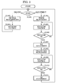
- FIG. 3 is a flowchart of the processing in the image-pickup system according to the first embodiment.
- FIG. 4 is a characteristic drawing showing luminance levels during white balance adjustment by imaging three-color color chart.
- FIG. 5 is a characteristic drawing showing luminance levels during color balance adjustment by imaging the three-color color chart.
- FIG. 6 is a flowchart of the color adjustment process in the image-pickup system according to the embodiment.
- FIG. 7 is a schematic drawing of a color chart according to a second embodiment of the present invention.
- FIG. 8 is a schematic drawing of a color chart according to a third embodiment of the present invention.
- FIG. 9 is a drawing showing control characteristics during white balance control.
- FIG. 10 is a block diagram of an image-pickup system of a conventional electronic camera.
- FIG. 11 is a flowchart of color adjustment process in a conventional image-pickup system.
- FIG. 12 is a characteristic drawing showing luminance levels when a white chart is imaged in the conventional image-pickup system.
- FIG. 13 is a characteristic drawing showing luminance levels when a seven-color color-bar chart is imaged in the conventional image-pickup system.
- FIG. 1 is a block diagram of an imaging system and an image adjustment system including a light box having a color chart in an embodiment of the present invention.
- the imaging system herein will be described by exemplifying an electronic camera.
- FIG. 1 there are shown a light box 100 for adjusting white balance and color balance using a three-color color chart, a lens 101 , a diaphragm 102 for adjusting light exposure, an imaging element 103 , an analog front end 104 for A/D conversion by sampling the output of the imaging element 103 , a signal processor 105 , an image signal output unit 106 , a white-balance adjustment unit 107 included in the signal processor 105 , a color-balance adjustment unit 108 included in the signal processor 105 , a photometric unit 109 , an exposure control unit 110 , a diaphragm drive unit 111 , a photometric region A 112 for providing a region where the photometric measurement is performed with the photometric unit 109 , a photometric region B 113 for providing a region where the photometric measurement is performed with the photometric unit 109 , a color-adjustment control unit 114 for controlling a color-adjustment process, a mode switching unit 115
- a signal is processed as follows: a light ray incident from the lens 101 is photo-electrically converted by the imaging element 103 after receiving appropriate exposure adjustment with the diaphragm 102 .
- the image signal photo-electrically converted in the imaging element 103 is then sampled and A/D converted in the analog front end 104 so as to produce an output from the image output unit 106 after receiving predetermined signal processing in the signal processor 105 .
- the mode switching unit 115 is then used to select the imaging mode, and the sampling region used for the photometry in the photometric unit 109 is selected from the photometric region A by the photometric region selecting unit 116 .
- the A/D converted image signal is sampled over a region defined by the photometric region A 112 so as to control an exposure amount in the exposure control unit 110 and the light amount allowed by the diaphragm 102 under control of the diaphragm drive unit 111 .
- center-weighted average photometry is used so that the center of an object and its vicinity is considered during photometry.
- the white-balance adjustment unit 107 and the color-balance adjustment unit 108 have been pre-adjusted and process a color signal based on the pre-adjustment so that an optimal color signal is produced.
- FIG. 2 is a schematic drawing of the color chart according to the first embodiment of the present invention. This color chart is used for color adjusting in the imaging system.
- FIG. 2 there are shown a light box 201 used as a reference light source for white balance adjustment, a color chart 202 composed of three colors of yellow, white, and red, a sampling region 203 for sampling a yellow portion of the color chart, a sampling region 204 for sampling a white portion of the color chart, and a sampling region 205 for sampling a red portion of the color chart.
- a light box 201 used as a reference light source for white balance adjustment
- a color chart 202 composed of three colors of yellow, white, and red
- a sampling region 203 for sampling a yellow portion of the color chart
- a sampling region 204 for sampling a white portion of the color chart
- a sampling region 205 for sampling a red portion of the color chart.
- FIG. 3 is a flowchart showing a process in the imaging system according to the embodiment of the present invention.
- FIG. 4 is a characteristic diagram showing luminance levels during white balance adjusting obtained by imaging the three-color color chart; and
- FIG. 5 is a characteristic diagram showing luminance levels during color balance adjusting obtained by imaging the three-color color chart.
- Step S 1301 the mode of the imaging system is determined, that is, it is determined whether the imaging mode or the adjustment mode has been selected (using mode switching unit 115 ).
- Step S 1302 the imaging mode is selected.
- the photometric unit 109 performs center-weighted average photometry over the photometric region A 112 selected by the selecting unit 116 .
- Step S 1303 image exposure is controlled by the exposure control unit 110 .
- Step S 1301 if the adjustment mode has been selected, color and white balance adjustment is then performed. This process will now be described.
- the color chart 100 shown in FIG. 1 is imaged, and the light ray incident on the lens 101 is photo-electrically converted by the imaging element 103 after receiving appropriate exposure adjustment with the diaphragm 102 and is sampled and A/D converted in the analog front end 104 .
- the mode switching unit 115 is then used to select the color adjusting mode, and the sampling region used for photometry in the photometric unit 109 is selected from the photometric region B 113 by the photometric region selecting unit 116 .
- This photometric region B 113 includes one or more divisions of the entire image, and is equivalent to color chart regions 203 to 205 shown in FIG. 2 .
- the region 204 is used for the white balance adjustment.
- the A/D converted image signal is first sampled over a white region 204 defined by the photometric region B 113 so as to perform partial photometry (white photometry) (Step S 1304 ). Based on the photometric result, an exposure amount is controlled in the exposure control unit 110 (Step S 1305 ) and the opening of the diaphragm 102 is controlled by the diaphragm drive unit 111 (Step S 1306 ).
- the luminance level herein of the exposure-controlled image signal becomes 50% for the central white portion as shown in FIG. 4 , so that the image signal of the color chart controlled at 50% is entered into the signal processor 105 .
- the color adjustment mode is selected by the mode switching unit 115 so that the white balance is adjusted in the white-balance adjustment unit 107 by the color-adjustment control unit 114 (Step S 1307 ).
- the color signal of a white portion of the color chart is then sampled. This uses a region identical to the region 204 used for the photometry.
- the white balance adjustment herein means the production of information, such as the control range for the white balance control, by sampling a reference image of a color temperature (white balance control attempts to control according to variation in environmental and lighting conditions when an object is imaged, by selecting a color temperature range corresponding to various lighting conditions).
- the adjusted control range to be used for the white balance control is obtained by sampling reference images of color temperatures.
- the light box 201 for use in the color adjustment is at a color temperature of 5600K, and the white balance adjustment uses the reference color temperature 5600K and a color temperature converted into 3200K by attaching an amber filter.
- the control range of the white balance and the color determination of a white portion of an object are controlled using these two temperatures as the references.
- the sampling region used for the photometry in the photometric unit 109 is selected from the photometric region B 113 by the photometric region selecting unit 116 .
- the regions 203 and 205 are used for the color balance adjustment.
- the designated yellow region 203 and the red region 205 of the photometric region B 113 are averaged and sampled to perform partial photometry (yellow/red photometry) (Step S 1308 ).
- an exposure amount is controlled in the exposure control unit 110 (Step S 1309 ) and the state (opening) of the diaphragm 102 is controlled by the diaphragm drive unit 111 (Step S 1310 ).
- the luminance level herein of the exposure-controlled image signal becomes 50% on average for yellow and red portions as shown in FIG. 5 , after which the image signal is entered to the signal processor 105 .
- An advantage of the present invention over conventional systems is that field angle can be aligned during chart imaging. This is because in center-weighted average photometry (in the photometric region A, for example) for conventional color adjustment of the entire image, if the peripheral region of the chart is reflected or the sides of the chart are cut off, the average luminance level is changed and an appropriate amount of exposure cannot be obtained.
- the partial photometry in the photometric region B, for example
- conditions cannot change as long as a different color is not entered into the photometric region or the photometric region does not extend beyond the region for photometry of the central portion of each color in a partial region of the image.
- the photometric region in the adjustment mode can be provided independently of the photometric region in the imaging mode, so that the influence of transfer of the other region due to dispersion in field angle is prevented, thus achieving improvement in image adjustment accuracy.
- This is the same for white balance adjustment, so that the field angle can be more aligned than in conventional systems.
- the color adjustment mode is selected by the mode switching unit 115 , so that the color balance is adjusted in the color-balance adjustment unit 108 by the control of the color-adjustment control unit 114 (Step S 1311 ).
- the color signals of the yellow portion and the red portion of the color chart are then sampled. Regions identical to the regions 204 and 205 used for the photometry are employed.
- the color balance herein means the adjustment of color tone and chroma of yellow and red in the chart in the same way as in the conventional example.
- the embodiment also provides desirable target values to properly reproduce the color of the human flesh (also a memory color). Since yellow and red do impact the color of the human flesh, they are adjusted to determine a matrix factor so that both the colors have desired target values.
- the exposure control unit 110 herein includes exposure control target values different for each measuring region. According to the embodiment, for adjustment of the color balance, a linear matrix factor and a gain are calculated with respect to color-difference signals Cr and Cb.
- Equation 1 and Equation 2 By respectively substituting yellow and red target values and sampled values into Equation 1 and Equation 2, the gain factors (11 and 12) and the linear matrix factors (k1 and k2) are obtained so as to have color-balance adjusted results.
- FIG. 6 is a flowchart showing a color adjustment process of the imaging system according to the embodiment of the present invention.
- FIG. 6 shows the process in the color-adjustment mode of FIG. 3 relative to FIG. 11 , which is a flowchart of the color adjustment process in a conventional image-pickup system.
- Steps S 1304 -S 1307 of FIG. 3 and steps S 603 -S 606 of FIG. 6 are equivalent and Steps S 1308 -S 1311 of FIG. 3 and Steps S 607 -S 610 of FIG. 6 are also equivalent.
- Steps S 1107 -S 1109 of FIG. 11 (culled out by broken lines) can be omitted from the process of FIG. 6 .
- the chart replacement and field angle alignment steps can be omitted, advantageously, the color-bar chart imaging step can be omitted as well.
- the chart replacement mechanism can be omitted in view of the automatic adjustment provided. This results in cost savings for adjustment equipment and space savings for adjustment tools. Since there is a room for the field angle alignment during the chart imaging as mentioned above, this has the advantage of the simplification of the field angle alignment mechanism.
- the three partial photometric regions B 203 to 205 are provided; alternatively, one region may be provided at the center so as to prevent exposure due to dispersion in field angle and multiple adjustments during imaging, although it may be difficult to automate adjustment and reduce the number of steps.
- the color chart according to the present embodiment is indeed an example so that the chart need not be composed of yellow, white, and red, and the photometric region may not be identical to the colorimetry region.
- the diaphragm 102 for controlling exposure is an example; other methods for accomplishing control can be used. For example, control can be implemented by using storage time or an electrical gain.
- the white balance adjustment and the color balance adjustment after the colorimetry may be carried out with different methods.
- FIG. 7 is a schematic drawing of a color chart according to the first embodiment of the present invention.
- FIG. 7 there are shown a light box 701 with a reference color temperature for white balance, a color chart 702 composed of yellow, white, and red, and a region 703 showing a field angle imaging the chart and a sampling range during adjustment in the image-pickup system.
- the central portion of each color is photometrically observed with partial photometry, so that conditions cannot change as long as a different color is not entered into the photometric region or the photometric region does not extend beyond the chart.
- the white balance and the color balance are adjusted using the color chart 702 shown in FIG. 7 .
- the color chart 702 has a white portion arranged in the center and yellow and red portions with areas larger than that of the white portion. During the color adjustment in the image-pickup system, the color chart 702 is imaged at a field angle shown by the region 703 while the adjustment itself is operated in a similar manner as in the first embodiment.
- the color chart 702 cannot turn aside the sampling region because the color chart 702 is larger than the imaging region in size even when the field angle is displaced aside the imaging region; and the field angle can be easily aligned at the center of the color chart 702 , so that by arranging the white portion in the center, the black portion of the peripheral frame can be prevented from being reflected, which is produced by the white portion arranged at the edge of the field angle. That is, according to the embodiment, the white balance can be obtained without being affected by the displacement of the field angle.
- the white portion is arranged at the center. Also, even if there is provided a color other than black in the vertical direction or in the horizontal direction without arranging the white portion at the center, the effect on the white balance is reduced, thus reducing inaccuracy in white balance correction. Since the light-source color temperature may be reduced in accuracy when the light box approaches the periphery from the center, the accuracy is improved if the white portion, which is liable to affect the color temperature, is arranged at the center.
- the field angle alignment itself may also be eliminated.
- the color chart according to the embodiment is indeed an example so that the chart need not be composed of yellow, white, and red; and the photometric region need not be identical to the colorimetry region.
- FIG. 8 is a schematic drawing of a color chart according to a third embodiment of the present invention.
- FIG. 8 there are shown a light box 801 with a reference color temperature of white balance, a color chart 802 composed of yellow, white, and red, a region 803 showing a yellow sampling range during color balance adjustment, a region 804 showing a white sampling range during white balance adjustment, a region 805 showing a red sampling range during color balance adjustment, and a region 806 showing a sampling range of a color-temperature conversion color during white balance adjustment.
- the color chart is provided with a color-temperature conversion color in the third embodiment.
- the light box 801 used for the adjustment has a color temperature of 5600K.
- the 5600K reference-color temperature and a color temperature converted to 3200K by putting an umber filter thereon are used so as to control the control range of the white balance and the color determination for determining a white portion of an object using these two temperatures as references.
- the umber color-temperature conversion filter is provided in addition to the light box at a color temperature of 5600K.
- the color-temperature conversion filter has a color-temperature conversion factor of 12 da mired (micro-reciprocal degrees) so as to convert 5600K into 3200K.
- the color chart 802 shown in FIG. 8 is provided with a color-temperature conversion portion by incorporating a color filter having a color-temperature conversion property equivalent to that of this color-temperature conversion into part of a white (achromatic color other than black) portion of the color chart 802 .
- this color-temperature conversion portion serves as the color-temperature conversion filter, eliminating separately having a color-temperature conversion filter.
- white balance adjustment is initially performed.
- the color chart 802 shown in FIG. 8 is imaged and the region 804 is sampled so as to make the partial photometry, and on the basis of the photometric result, the exposure is controlled.
- the white balance is adjusted at a color temperature of 5600K.
- the color signal of a white portion of the color chart is sampled.
- the region 806 is sampled so as to make the partial photometry in the same way, and on the basis of the photometric result, the exposure is controlled.
- the white balance is adjusted at a color temperature of 3200K.
- the color signal of an umber portion (color-temperature conversion color) of the chart is sampled. This uses a region identical to the region 806 used for the photometry.
- the white balance refers to sampling reference images at two color temperatures so as to obtain a control range of the white balance and the color determination for determining a white portion of an object using these two temperatures as references.
- FIG. 9 is a drawing showing the gain for R and B for white balance control for different color temperatures.
- FIG. 9 there are shown a reference point 900 of the gain of R and B signals when the white balance is fitted to the reference color temperature of 5600K, a reference point 901 of the gain of R and B signals when the white balance is fitted to the reference color temperature of 3200K, and a white balance control characteristic 902 fitted to color temperature changes using the reference point 900 and the reference point 901 as references.
- the white balance control characteristic 902 is determined by determining the reference points 900 and 901 , so that in the imaging mode, the white balance is controlled on the basis of the control characteristic 902 .
- the color balance is adjusted thereafter in the same way as in the first embodiment.
- the color chart since the color chart includes the color-temperature conversion filter, it is not necessary to separately prepare a filter, and a mechanism for automatically inserting a filter can be eliminated during the adjustment.
- the color chart according to the embodiment is indeed an example so that the chart need not be composed of white, umber (color-temperature conversion color), and red.
- the color chart may be a combination of blue, green, etc.
- the photometric region need not be identical to the colorimetry region. Other techniques may also be employed for white balance adjustment after the colorimetry.
- the white balance is used for white color; however, it may also be gray or an achromatic color other than black capable.
- the present invention can also be achieved by providing a storage medium storing program codes for performing the aforesaid processes to an image sensing system or device, reading the program codes, by a CPU or MPU of the image sensing system or device, from the storage medium, then executing the program.
- the program codes read from the storage medium realize the functions according to the embodiments, and the storage medium storing the program codes constitutes the invention.
- the storage medium such as a floppy disk, a hard disk, an optical disk, a magneto-optical disk, CD-ROM, CD-R, a magnetic tape, a non-volatile type memory card, and ROM, and RAM, and computer network, such as LAN (local area network) and WAN (wide area network), can be used for providing the program codes.
- LAN local area network
- WAN wide area network
- the present invention includes a case where an OS (operating system) or the like working on the computer performs a part or entire processes in accordance with designations of the program codes and realizes functions according to the above embodiments.
- the present invention also includes a case where, after the program codes read from the storage medium are written in a function expansion card which is inserted into the image sensing system or device or in a memory provided in a function expansion unit which is connected to the image sensing system or device, CPU or the like contained in the function expansion card or unit performs part or entire process in accordance with designations of the program codes and realizes functions of the above embodiments.
- the storage medium stores program codes corresponding to the flowchart of FIG. 3 or 7 , described in the embodiments.
Landscapes
- Engineering & Computer Science (AREA)
- Multimedia (AREA)
- Signal Processing (AREA)
- Color Television Image Signal Generators (AREA)
- Processing Of Color Television Signals (AREA)
- Exposure Control For Cameras (AREA)
- Studio Devices (AREA)
Applications Claiming Priority (2)
| Application Number | Priority Date | Filing Date | Title |
|---|---|---|---|
| JP2004-015782 | 2004-01-23 | ||
| JP2004015782A JP4290022B2 (ja) | 2004-01-23 | 2004-01-23 | 撮像装置及び画像調整方法 |
Publications (2)
| Publication Number | Publication Date |
|---|---|
| US20050162542A1 US20050162542A1 (en) | 2005-07-28 |
| US7808545B2 true US7808545B2 (en) | 2010-10-05 |
Family
ID=34792453
Family Applications (1)
| Application Number | Title | Priority Date | Filing Date |
|---|---|---|---|
| US11/035,241 Active 2027-10-19 US7808545B2 (en) | 2004-01-23 | 2005-01-13 | Image-pickup device, color chart, image adjusting method, and image adjusting system |
Country Status (2)
| Country | Link |
|---|---|
| US (1) | US7808545B2 (ja) |
| JP (1) | JP4290022B2 (ja) |
Cited By (3)
| Publication number | Priority date | Publication date | Assignee | Title |
|---|---|---|---|---|
| US20120086830A1 (en) * | 2010-10-08 | 2012-04-12 | Manabu Ichikawa | Image processing device, white balance correction method, and imaging device |
| US8786712B1 (en) * | 2013-04-08 | 2014-07-22 | Iix Inc. | Luminance measurement method, luminance measurement device, and image quality adjustment technique using the method and device |
| US20140300756A1 (en) * | 2013-04-08 | 2014-10-09 | Iix Inc. | Luminance measurement method, luminance measurement device, and image quality adjustment technique using the method and device |
Families Citing this family (6)
| Publication number | Priority date | Publication date | Assignee | Title |
|---|---|---|---|---|
| JP4290022B2 (ja) * | 2004-01-23 | 2009-07-01 | キヤノン株式会社 | 撮像装置及び画像調整方法 |
| US7920167B2 (en) * | 2005-04-29 | 2011-04-05 | Hewlett-Packard Development Company, L.P. | Method and apparatus for the creation of image capture device parameter curves |
| JP5029187B2 (ja) * | 2007-07-20 | 2012-09-19 | 株式会社ニコン | 色座標変換装置、撮像装置、色座標変換プログラム、色座標変換方法 |
| CN103621068B (zh) * | 2011-06-22 | 2015-12-23 | 株式会社日立国际电气 | 电视摄像机装置 |
| CN105491285B (zh) * | 2015-12-03 | 2019-02-15 | 浙江宇视科技有限公司 | 一种pir摄像机工作模式切换方法及装置 |
| US11095865B2 (en) * | 2017-07-24 | 2021-08-17 | Hewlett-Packard Development Company, L.P. | Color balance in electronic devices |
Citations (10)
| Publication number | Priority date | Publication date | Assignee | Title |
|---|---|---|---|---|
| US4575124A (en) * | 1982-04-05 | 1986-03-11 | Ampex Corporation | Reproducible gray scale test chart for television cameras |
| US5602615A (en) * | 1994-11-16 | 1997-02-11 | Nikon Corporation | Photometric device to determine a correct photometric value of a spot photometric region |
| JPH11113007A (ja) | 1997-09-30 | 1999-04-23 | Ricoh Co Ltd | デジタルカメラ |
| US6256062B1 (en) * | 1996-08-30 | 2001-07-03 | Sony Corporation | Color correction apparatus for matching colors in a signal output from a first image apparatus with those from a second image apparatus |
| US20020057847A1 (en) * | 2000-11-15 | 2002-05-16 | Nikon Corporation | Image-capturing device |
| US6618079B1 (en) * | 1997-04-01 | 2003-09-09 | Sony Corporation | Color connecting apparatus for a video camera |
| US6633330B1 (en) * | 1996-12-24 | 2003-10-14 | Mitsubishi Denki Kabushiki Kaisha | Color characteristic measuring apparatus and method, and storage medium of image pickup data |
| JP2004023209A (ja) | 2002-06-13 | 2004-01-22 | Nec Viewtechnology Ltd | 資料提示装置 |
| US20050162542A1 (en) * | 2004-01-23 | 2005-07-28 | Canon Kabushiki Kaisha | Image-pickup device, color chart, image adjusting method, and image adjusting system |
| US6961086B1 (en) * | 1999-02-08 | 2005-11-01 | Fuji-Photo Film Co., Ltd | Photographing apparatus for correcting white balance of an image signal and a color correction coefficient of image data |
-
2004
- 2004-01-23 JP JP2004015782A patent/JP4290022B2/ja not_active Expired - Lifetime
-
2005
- 2005-01-13 US US11/035,241 patent/US7808545B2/en active Active
Patent Citations (10)
| Publication number | Priority date | Publication date | Assignee | Title |
|---|---|---|---|---|
| US4575124A (en) * | 1982-04-05 | 1986-03-11 | Ampex Corporation | Reproducible gray scale test chart for television cameras |
| US5602615A (en) * | 1994-11-16 | 1997-02-11 | Nikon Corporation | Photometric device to determine a correct photometric value of a spot photometric region |
| US6256062B1 (en) * | 1996-08-30 | 2001-07-03 | Sony Corporation | Color correction apparatus for matching colors in a signal output from a first image apparatus with those from a second image apparatus |
| US6633330B1 (en) * | 1996-12-24 | 2003-10-14 | Mitsubishi Denki Kabushiki Kaisha | Color characteristic measuring apparatus and method, and storage medium of image pickup data |
| US6618079B1 (en) * | 1997-04-01 | 2003-09-09 | Sony Corporation | Color connecting apparatus for a video camera |
| JPH11113007A (ja) | 1997-09-30 | 1999-04-23 | Ricoh Co Ltd | デジタルカメラ |
| US6961086B1 (en) * | 1999-02-08 | 2005-11-01 | Fuji-Photo Film Co., Ltd | Photographing apparatus for correcting white balance of an image signal and a color correction coefficient of image data |
| US20020057847A1 (en) * | 2000-11-15 | 2002-05-16 | Nikon Corporation | Image-capturing device |
| JP2004023209A (ja) | 2002-06-13 | 2004-01-22 | Nec Viewtechnology Ltd | 資料提示装置 |
| US20050162542A1 (en) * | 2004-01-23 | 2005-07-28 | Canon Kabushiki Kaisha | Image-pickup device, color chart, image adjusting method, and image adjusting system |
Cited By (5)
| Publication number | Priority date | Publication date | Assignee | Title |
|---|---|---|---|---|
| US20120086830A1 (en) * | 2010-10-08 | 2012-04-12 | Manabu Ichikawa | Image processing device, white balance correction method, and imaging device |
| US8872936B2 (en) * | 2010-10-08 | 2014-10-28 | Olympus Imaging Corp. | Image processing device, white balance correction method, and imaging device |
| US8786712B1 (en) * | 2013-04-08 | 2014-07-22 | Iix Inc. | Luminance measurement method, luminance measurement device, and image quality adjustment technique using the method and device |
| US20140300756A1 (en) * | 2013-04-08 | 2014-10-09 | Iix Inc. | Luminance measurement method, luminance measurement device, and image quality adjustment technique using the method and device |
| US8941742B2 (en) * | 2013-04-08 | 2015-01-27 | Iix Inc. | Luminance measurement method, luminance measurement device, and image quality adjustment technique using the method and device |
Also Published As
| Publication number | Publication date |
|---|---|
| US20050162542A1 (en) | 2005-07-28 |
| JP2005210484A (ja) | 2005-08-04 |
| JP4290022B2 (ja) | 2009-07-01 |
Similar Documents
| Publication | Publication Date | Title |
|---|---|---|
| US7808545B2 (en) | Image-pickup device, color chart, image adjusting method, and image adjusting system | |
| US7630107B2 (en) | Printer system and image processing system having image correcting function | |
| US6075562A (en) | Image inputting apparatus | |
| US5289268A (en) | Apparatus using brightness information from a photometering circuit and a brightness-converted green component from a color metering circuit to ultimately adjust white balance | |
| US6952225B1 (en) | Method and apparatus for automatic white balance adjustment based upon light source type | |
| US7969483B2 (en) | White balance control method, imaging apparatus and storage medium storing white balance control program | |
| EP0658058B1 (en) | White balance adjustment apparatus | |
| JP4324404B2 (ja) | 固体撮像装置及びデジタルカメラ | |
| EP0523633A1 (en) | Color image pickup device having color temperature converting filters | |
| EP2426927B1 (en) | Image processing apparatus, image processing method and computer program | |
| JP2002287235A (ja) | 多色シーンおよび/またはシーンの多色撮影画像における主色を表示するカメラおよび方法 | |
| US20020118967A1 (en) | Color correcting flash apparatus, camera, and method | |
| US6963362B1 (en) | Image pickup apparatus having flash and color adjustment control | |
| JP2003259389A (ja) | 撮像装置 | |
| US6927792B1 (en) | Television camera and white balance correcting method | |
| JP3821729B2 (ja) | デジタルカメラ | |
| JP4049257B2 (ja) | 固体撮像装置及びデジタルカメラ | |
| JP4178788B2 (ja) | カラーチャート、画像データ生成装置、カラーチャートを利用したプロファイル作成方法、プロファイル作成プログラムを記録した記録媒体 | |
| JPH0545745A (ja) | 写真焼付露光量の制御方法 | |
| JP3142603B2 (ja) | 画像撮影装置のホワイトバランス装置 | |
| KR20060131754A (ko) | 이미지 데이터 변환 절차를 효과적으로 수행하는 시스템 및방법 | |
| JP3491032B2 (ja) | 電子スチルビデオカメラの自動白バランス制御回路 | |
| JP2009239323A (ja) | 映像信号処理装置 | |
| JP3535678B2 (ja) | スチルビデオカメラのホワイトバランス調整装置 | |
| JP3539883B2 (ja) | 画像処理方法および装置、記録媒体、撮像装置並びに画像再生装置 |
Legal Events
| Date | Code | Title | Description |
|---|---|---|---|
| AS | Assignment |
Owner name: CANON KABUSHIKI KAISHA, JAPAN Free format text: ASSIGNMENT OF ASSIGNORS INTEREST;ASSIGNOR:NAKAYAMA, SATOSHI;REEL/FRAME:016192/0831 Effective date: 20041227 |
|
| STCF | Information on status: patent grant |
Free format text: PATENTED CASE |
|
| FEPP | Fee payment procedure |
Free format text: PAYOR NUMBER ASSIGNED (ORIGINAL EVENT CODE: ASPN); ENTITY STATUS OF PATENT OWNER: LARGE ENTITY |
|
| FPAY | Fee payment |
Year of fee payment: 4 |
|
| MAFP | Maintenance fee payment |
Free format text: PAYMENT OF MAINTENANCE FEE, 8TH YEAR, LARGE ENTITY (ORIGINAL EVENT CODE: M1552) Year of fee payment: 8 |
|
| MAFP | Maintenance fee payment |
Free format text: PAYMENT OF MAINTENANCE FEE, 12TH YEAR, LARGE ENTITY (ORIGINAL EVENT CODE: M1553); ENTITY STATUS OF PATENT OWNER: LARGE ENTITY Year of fee payment: 12 |