US7802491B2 - Device for dampening torsional vibrations and arrangement - Google Patents
Device for dampening torsional vibrations and arrangement Download PDFInfo
- Publication number
- US7802491B2 US7802491B2 US11/562,245 US56224506A US7802491B2 US 7802491 B2 US7802491 B2 US 7802491B2 US 56224506 A US56224506 A US 56224506A US 7802491 B2 US7802491 B2 US 7802491B2
- Authority
- US
- United States
- Prior art keywords
- flywheel mass
- centering sleeve
- centering
- sleeve
- arrangement
- Prior art date
- Legal status (The legal status is an assumption and is not a legal conclusion. Google has not performed a legal analysis and makes no representation as to the accuracy of the status listed.)
- Expired - Fee Related, expires
Links
Images


Classifications
-
- F—MECHANICAL ENGINEERING; LIGHTING; HEATING; WEAPONS; BLASTING
- F16—ENGINEERING ELEMENTS AND UNITS; GENERAL MEASURES FOR PRODUCING AND MAINTAINING EFFECTIVE FUNCTIONING OF MACHINES OR INSTALLATIONS; THERMAL INSULATION IN GENERAL
- F16F—SPRINGS; SHOCK-ABSORBERS; MEANS FOR DAMPING VIBRATION
- F16F15/00—Suppression of vibrations in systems; Means or arrangements for avoiding or reducing out-of-balance forces, e.g. due to motion
- F16F15/10—Suppression of vibrations in rotating systems by making use of members moving with the system
- F16F15/12—Suppression of vibrations in rotating systems by making use of members moving with the system using elastic members or friction-damping members, e.g. between a rotating shaft and a gyratory mass mounted thereon
- F16F15/131—Suppression of vibrations in rotating systems by making use of members moving with the system using elastic members or friction-damping members, e.g. between a rotating shaft and a gyratory mass mounted thereon the rotating system comprising two or more gyratory masses
- F16F15/13142—Suppression of vibrations in rotating systems by making use of members moving with the system using elastic members or friction-damping members, e.g. between a rotating shaft and a gyratory mass mounted thereon the rotating system comprising two or more gyratory masses characterised by the method of assembly, production or treatment
- F16F15/1315—Multi-part primary or secondary masses, e.g. assembled from pieces of sheet steel
-
- F—MECHANICAL ENGINEERING; LIGHTING; HEATING; WEAPONS; BLASTING
- F16—ENGINEERING ELEMENTS AND UNITS; GENERAL MEASURES FOR PRODUCING AND MAINTAINING EFFECTIVE FUNCTIONING OF MACHINES OR INSTALLATIONS; THERMAL INSULATION IN GENERAL
- F16F—SPRINGS; SHOCK-ABSORBERS; MEANS FOR DAMPING VIBRATION
- F16F15/00—Suppression of vibrations in systems; Means or arrangements for avoiding or reducing out-of-balance forces, e.g. due to motion
- F16F15/10—Suppression of vibrations in rotating systems by making use of members moving with the system
- F16F15/12—Suppression of vibrations in rotating systems by making use of members moving with the system using elastic members or friction-damping members, e.g. between a rotating shaft and a gyratory mass mounted thereon
- F16F15/121—Suppression of vibrations in rotating systems by making use of members moving with the system using elastic members or friction-damping members, e.g. between a rotating shaft and a gyratory mass mounted thereon using springs as elastic members, e.g. metallic springs
- F16F15/124—Elastomeric springs
- F16F15/126—Elastomeric springs consisting of at least one annular element surrounding the axis of rotation
-
- Y—GENERAL TAGGING OF NEW TECHNOLOGICAL DEVELOPMENTS; GENERAL TAGGING OF CROSS-SECTIONAL TECHNOLOGIES SPANNING OVER SEVERAL SECTIONS OF THE IPC; TECHNICAL SUBJECTS COVERED BY FORMER USPC CROSS-REFERENCE ART COLLECTIONS [XRACs] AND DIGESTS
- Y10—TECHNICAL SUBJECTS COVERED BY FORMER USPC
- Y10T—TECHNICAL SUBJECTS COVERED BY FORMER US CLASSIFICATION
- Y10T74/00—Machine element or mechanism
- Y10T74/21—Elements
- Y10T74/2121—Flywheel, motion smoothing-type
- Y10T74/2131—Damping by absorbing vibration force [via rubber, elastomeric material, etc.]
Definitions
- the invention relates to a device for dampening torsional vibrations, comprising a centering sleeve for the reception of a rotatable element and a flywheel mass. Furthermore, the invention relates to an arrangement for dampening torsional vibrations which comprises a device.
- Such devices and arrangements are already known from prior art. They serve for reducing vibrations of a shaft and are used amongst others as absorbers which are provided with a flywheel rim as absorber mass or flywheel mass. Also, flexible couplings, so called hardy disks, are frequently used for the torque-transmitting connection of two shaft ends.
- the radial stiffness as well as the mounting accuracy of such elastomeric couplings is not sufficient for adequately aligning the two shaft ends in case of different rotational speeds and for ensuring a dynamic stability. This may lead to a misalignment of the shafts which again results in noise or vibration problems due to unbalances at higher engine speeds.
- centering sleeves are used which are used to functionally center the shaft ends.
- the invention is based on the objective to realize an arrangement having a constructively simple arrangement and a high dynamic stability.
- the aforementioned objective is solved by the features of claim 1 .
- the initially mentioned device is characterized by the fact that the centering sleeves and the flywheel mass are connected to each other.
- connection of a centering sleeve with a flywheel mass allows for an effective counteraction of the torsional vibrations.
- the centering sleeve and the flywheel mass can be designed as preinstalled components. Said design guarantees that complex procedures for centering the flywheel mass in relation to the shaft can be avoided when the component is installed. An additional centering between the shaft and the balanced weight is not necessary. Thus, source of errors are effectively eliminated.
- the centering sleeve and the flywheel mass can be connected by means of an elastomer arranged at the outer circumference of the centering sleeve. Thereby, it is ensured that the flywheel mass can be moved in relation to the centering sleeve and can meet torsional vibrations.
- the elastomer can be designed as continuous layer or as discontinuous elastomeric track. In a continuous layer, a particularly high stiffness can be realized. In a discontinuous layer, a low torsional stiffness with the radial stiffness being comparatively high can be realized. Said stiffness conditions can be adjusted according to the number of recesses.
- the centering sleeve and the flywheel mass can be connected to each other by means of an interference fit and/or a vulcanization process.
- a vulcanization process ensures a reliable connection between the flywheel mass and the centering sleeve. It is a possible option, to vulcanize an elastomer either to the centering sleeve or only to the flywheel mass, wherein the overall connection is achieved by an interference fit. Thanks to said embodiment, the occurring shrinkage stresses are minimized.
- a plurality of cavities namely centering sleeves with elastomers can be arranged in a vulcanization device and thus a cost-effective production process is possible.
- a particularly reliable connection could be achieved by connecting the elastomer both with the centering sleeve and with the flywheel mass by means of vulcanization. Thereby, a rubber-metal connection is created.
- the flywheel mass and the centering sleeve are only connected to each other by an interference fit of an elastomeric layer or a rubber ring.
- a rubber-metal connection is completely avoided and the rubber ring or the elastomer are driven in. Thereby, a particularly quick production process can be realized.
- the centering sleeve and the flywheel mass can be arranged concentrically.
- the concentric arrangement ensures that unbalances are avoided.
- the centering sleeve could at least partially be arranged within the flywheel mass. Said construction ensures particular compactness, by means of which a space-saving design is realized. Thus, two shaft ends can be arranged in a particularly compact manner in a torque-transmitting connection.
- an elastic layer could be arranged within the centering sleeve. Thereby, it is ensured that a journal of a shaft or an end of a shaft can be received within the centering sleeve by interference fitting.
- the elastic layer can be designed as elastomer or rubber.
- the elastic layer within the centering sleeve is at least partially spherical. Because of the spherical design, the elastic layer, due to its concave shape, is mainly subjected to shearing stress. In this connection it is advantageous that due to the concave elastic layer a high radial stiffness can be realized almost independently from its thickness, since mainly compression-tension strains occur when a radial drifting takes place. Thus, the ware-out thereof is minimized.
- An inner sleeve 7 could be adjoining to the elastic layer 4 . Said measure allows for a particularly exact centering of a shaft end since the inner sleeve 7 can be turned after being embedded in the elastic layer 4 in order to compensate for unevennesses or acentric positionings.
- the inner sleeve could be made of bronze in order to ensure a good wear resistance. If the inner sleeve is made of plastic, the production thereof is particularly cost-efficient.
- the inner sleeve and/or the elastic layer could have a spherical design. In order to avoid repetitions regarding the advantages of a spherical design, reference is made to the above descriptions.
- the flywheel mass could be designed as deep drawn part. This specific embodiment allows for a particularly space-saving and compact construction of the flywheel mass to be realized.
- the flywheel mass could be designed as flat sheet which can be unproblematically inserted in a small space.
- the flywheel mass can be inserted in a small space between a flexible coupling, for example an elastomeric coupling and in particular a hardy disk, and a shaft flange. All in all, the space between the shaft flange and the flexible coupling is optimally used.
- a flywheel mass is positioned which can additionally absorb the torsional vibrations independently from the flexible coupling.
- the initially mentioned objective is furthermore solved by means of an arrangement for dampening torsional vibrations comprising an aforedescribed device and a flexible coupling, wherein two shaft ends are connected in a torque-transmitting way.
- the flexible coupling may be an elastomeric coupling, particularly a hardy disk provided with sleeves. Flanges with three arms or several arms which are associated to the shafts can be connected with said sleeves.
- the flywheel mass of the described device can counteract and absorb and dampen the torsional vibrations, wherein, at the same time, the shaft ends are effectively centered.
- the flywheel mass which is designed as deep-drawn part.
- the flywheel mass is directly connected with the centering sleeve by means of an elastomeric layer. Consequently, the elastomeric layer can be arranged at a very close distance to the center, by means of which the radial stiffness between the centering sleeve and the flywheel mass is significantly increased. Thereby, a significant unbalance caused by radial drifting of the flywheel mass is avoided. All in all, vibration and noise problems of drive shafts can be effectively avoided.
- an arrangement or a device of the aforedescribed kind can be used for drive shafts.
- a flexible coupling is used which can be complemented in a particularly advantageous manner by the inventive device.
- FIG. 1 shows an inventive device with a centering sleeve and a flywheel mass in a schematic display
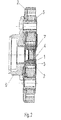
- FIG. 2 shows an arrangement including a device according to FIG. 1
- FIG. 1 shows a device for dampening torsional vibrations with a centering sleeve 1 for the reception of a rotatable element. Furthermore, the device shows a flywheel mass 2 . The centering sleeve 1 and the flywheel mass 2 are connected to each other.
- connection is of such kind that a relative movement of the centering sleeve and the flywheel mass can be realized.
- the centering sleeve 1 and the flywheel mass 2 are designed as preinstalled components, wherein the centering sleeve 1 and the flywheel mass 2 are connected by means of an elastomer 3 which is arranged on the outer circumference of the centering sleeve 1 .
- the centering sleeve 1 and the flywheel mass 2 may be connected by means of an interference fit and/or a vulcanization process.
- the elastomer is vulcanized to the outer circumference of the centering sleeve.
- the centering sleeve 1 with the elastomer 3 vulcanized thereto can be integrated into the flywheel mass 2 by means of interference fit.
- the centering sleeve 1 and the flywheel mass 2 are concentrically arranged, wherein the centering sleeve 1 is at least partially arranged within the flywheel mass 2 .
- An elastic layer 4 comprising an elastomer is arranged within the centering sleeve 1 .
- the flywheel mass 2 is designed as deep-drawn layer. Precisely, the flywheel mass 2 is designed as deep-drawn sheet.
- the centering sleeve 1 has a cylindrical shape and tapers towards one end.
- the part of the centering sleeve 1 provided with the elastic layer 4 receives a journal of a shaft by means of interference fitting.
- the interference fit is realized between the elastic layer 4 and the journal of the shaft.
- the part of the centering sleeve 1 opposed thereto is inserted in a shaft flange by means of interference fitting.
- FIG. 2 shows an arrangement for dampening torsional vibrations comprising a device according to FIG. 1 and a flexible coupling 5 .
- the flexible coupling 5 is designed as hardy disk.
- two shaft ends are connected to each other in a torque-transmitting way.
- the torque-transmitting connection is realized by means of a flange 6 which may be designed as a flange having three arms.
- said flange 6 forms a torque transmitting connection to a further flange of the other shaft which is not shown herein.
- the flywheel mass 2 is situated in an installation space defined by the flange 6 and the flexible coupling 5 .
- the design of the flywheel mass 2 as deep-drawn sheet allows for the flywheel mass to be arranged in said small installation space.
- the flywheel mass 2 can be provided with recesses which may at least partially be penetrated by the flexible coupling 5 .
Landscapes
- Engineering & Computer Science (AREA)
- General Engineering & Computer Science (AREA)
- Physics & Mathematics (AREA)
- Acoustics & Sound (AREA)
- Aviation & Aerospace Engineering (AREA)
- Mechanical Engineering (AREA)
- Manufacturing & Machinery (AREA)
- Shafts, Cranks, Connecting Bars, And Related Bearings (AREA)
- Motor Power Transmission Devices (AREA)
Applications Claiming Priority (3)
| Application Number | Priority Date | Filing Date | Title |
|---|---|---|---|
| DE102005055800.3 | 2005-11-21 | ||
| DE102005055800A DE102005055800B4 (de) | 2005-11-21 | 2005-11-21 | Vorrichtung zur Dämpfung von Torsionsschwingungen und Anordnung |
| DE102005055800 | 2005-11-21 |
Publications (2)
| Publication Number | Publication Date |
|---|---|
| US20070163379A1 US20070163379A1 (en) | 2007-07-19 |
| US7802491B2 true US7802491B2 (en) | 2010-09-28 |
Family
ID=37989564
Family Applications (1)
| Application Number | Title | Priority Date | Filing Date |
|---|---|---|---|
| US11/562,245 Expired - Fee Related US7802491B2 (en) | 2005-11-21 | 2006-11-21 | Device for dampening torsional vibrations and arrangement |
Country Status (3)
| Country | Link |
|---|---|
| US (1) | US7802491B2 (de) |
| JP (1) | JP2007139195A (de) |
| DE (1) | DE102005055800B4 (de) |
Cited By (3)
| Publication number | Priority date | Publication date | Assignee | Title |
|---|---|---|---|---|
| US20160195160A1 (en) * | 2013-09-04 | 2016-07-07 | Sueddeutsche Gelenkscheibenfabrik Gmbh & Co. Kg | Torsional vibration damper |
| US20160298720A1 (en) * | 2015-04-08 | 2016-10-13 | Markus Duerre | Damper for a drive train |
| US11225138B2 (en) * | 2018-06-27 | 2022-01-18 | Neapco Intellectual Property Holdings, Llc | Center bearing assembly including a rotatable weld collar with a tuned damper |
Families Citing this family (13)
| Publication number | Priority date | Publication date | Assignee | Title |
|---|---|---|---|---|
| DE102005037135B4 (de) * | 2005-08-06 | 2007-07-05 | Mtu Friedrichshafen Gmbh | Zentrierhülse |
| TWI433588B (zh) * | 2005-12-13 | 2014-04-01 | Koninkl Philips Electronics Nv | 發光二極體發光裝置 |
| US7658506B2 (en) * | 2006-05-12 | 2010-02-09 | Philips Solid-State Lighting Solutions, Inc. | Recessed cove lighting apparatus for architectural surfaces |
| PL2087776T3 (pl) * | 2006-10-19 | 2015-05-29 | Philips Lighting North America Corp | Pracujące w sieci oprawy oświetleniowe oparte na diodach LED oraz sposoby zasilania i sterowania nimi |
| WO2008060469A2 (en) * | 2006-11-10 | 2008-05-22 | Philips Solid-State Lighting Solutions, Inc. | Methods and apparatus for controlling series-connected leds |
| US20080136796A1 (en) * | 2006-11-20 | 2008-06-12 | Philips Solid-State Lighting Solutions | Methods and apparatus for displaying images on a moving display unit |
| JP5135354B2 (ja) * | 2007-01-05 | 2013-02-06 | フィリップス ソリッド−ステート ライティング ソリューションズ インコーポレイテッド | 抵抗性負荷を模擬する方法及び装置 |
| US20100195949A1 (en) * | 2007-10-25 | 2010-08-05 | Takashi Yagi | Rolling bearing |
| US20090128921A1 (en) * | 2007-11-15 | 2009-05-21 | Philips Solid-State Lighting Solutions | Led collimator having spline surfaces and related methods |
| DE102008020454B4 (de) | 2008-04-23 | 2018-04-19 | Vibracoustic Gmbh | Gelenkscheibe mit Dämpfungssprung in der torsionalen Kennlinie und Anordnung |
| DE102010006363C5 (de) | 2010-01-29 | 2022-01-20 | Vibracoustic Se | Umwuchtoptimierter Gelenkwellentilger |
| JP5757456B2 (ja) * | 2011-03-24 | 2015-07-29 | Nok株式会社 | 駆動系ダイナミックダンパー |
| EP2931581B1 (de) * | 2012-12-13 | 2018-07-18 | Vibracoustic North America, L.P. | Antriebswellendämpfer und montageverfahren |
Citations (4)
| Publication number | Priority date | Publication date | Assignee | Title |
|---|---|---|---|---|
| US4178811A (en) * | 1977-06-15 | 1979-12-18 | Wallace Murray Corporation | Meta reinforced plastic damper hub |
| US4322062A (en) * | 1979-12-26 | 1982-03-30 | Grumman Aerospace Corporation | Torsion spring damper |
| US5474499A (en) * | 1993-07-12 | 1995-12-12 | The United States Of America As Represented By The Secretary Of The Navy | Flexible drive shaft coupling |
| US6068555A (en) * | 1995-08-24 | 2000-05-30 | Sgf Suddeutsche Gelenkscheibenfabrik Gmbh & Co. Kg | Vibration damping, torsionally elastic shaft coupling, especially for a motor vehicle power train |
Family Cites Families (5)
| Publication number | Priority date | Publication date | Assignee | Title |
|---|---|---|---|---|
| DE4017913A1 (de) * | 1990-06-02 | 1991-12-05 | Freudenberg Carl Fa | Rotationskoerper |
| DE4029429A1 (de) * | 1990-09-17 | 1992-03-19 | Schloemann Siemag Ag | Vorrichtung zum wechseln der presswerkzeuge einer stauchpresse |
| DE4325509C2 (de) * | 1992-07-31 | 1997-02-27 | Metzeler Gimetall Ag | Vorrichtung zur Dämpfung von Schwingungen an Kurbelwellen |
| JPH09184544A (ja) * | 1995-12-29 | 1997-07-15 | Du Pont Toray Co Ltd | 吸振体 |
| JP2003139196A (ja) * | 2001-10-31 | 2003-05-14 | Tokai Rubber Ind Ltd | ダイナミックダンパ |
-
2005
- 2005-11-21 DE DE102005055800A patent/DE102005055800B4/de not_active Expired - Fee Related
-
2006
- 2006-11-17 JP JP2006311967A patent/JP2007139195A/ja not_active Withdrawn
- 2006-11-21 US US11/562,245 patent/US7802491B2/en not_active Expired - Fee Related
Patent Citations (4)
| Publication number | Priority date | Publication date | Assignee | Title |
|---|---|---|---|---|
| US4178811A (en) * | 1977-06-15 | 1979-12-18 | Wallace Murray Corporation | Meta reinforced plastic damper hub |
| US4322062A (en) * | 1979-12-26 | 1982-03-30 | Grumman Aerospace Corporation | Torsion spring damper |
| US5474499A (en) * | 1993-07-12 | 1995-12-12 | The United States Of America As Represented By The Secretary Of The Navy | Flexible drive shaft coupling |
| US6068555A (en) * | 1995-08-24 | 2000-05-30 | Sgf Suddeutsche Gelenkscheibenfabrik Gmbh & Co. Kg | Vibration damping, torsionally elastic shaft coupling, especially for a motor vehicle power train |
Cited By (7)
| Publication number | Priority date | Publication date | Assignee | Title |
|---|---|---|---|---|
| US20160195160A1 (en) * | 2013-09-04 | 2016-07-07 | Sueddeutsche Gelenkscheibenfabrik Gmbh & Co. Kg | Torsional vibration damper |
| US20160298720A1 (en) * | 2015-04-08 | 2016-10-13 | Markus Duerre | Damper for a drive train |
| KR20170135934A (ko) * | 2015-04-08 | 2017-12-08 | 비브라코우스틱 게엠베하 | 드라이브 트레인용 진동 흡수기 |
| CN107636345A (zh) * | 2015-04-08 | 2018-01-26 | 威巴克公司 | 用于传动系的减振器 |
| US9909642B2 (en) * | 2015-04-08 | 2018-03-06 | Vibracoustic Gmbh | Damper for a drive train |
| CN107636345B (zh) * | 2015-04-08 | 2021-01-12 | 威巴克公司 | 用于传动系的减振器 |
| US11225138B2 (en) * | 2018-06-27 | 2022-01-18 | Neapco Intellectual Property Holdings, Llc | Center bearing assembly including a rotatable weld collar with a tuned damper |
Also Published As
| Publication number | Publication date |
|---|---|
| US20070163379A1 (en) | 2007-07-19 |
| JP2007139195A (ja) | 2007-06-07 |
| DE102005055800B4 (de) | 2008-01-03 |
| DE102005055800A1 (de) | 2007-05-24 |
Similar Documents
| Publication | Publication Date | Title |
|---|---|---|
| US7802491B2 (en) | Device for dampening torsional vibrations and arrangement | |
| US6312340B1 (en) | Hollow drive shaft with integrated vibration absorber | |
| US4781659A (en) | Torsional vibration damper with a V-belt pulley connected thereto | |
| US7600601B2 (en) | Tunable mass damper for a drive shaft center support bearing | |
| US8591344B2 (en) | Arrangement with a mass damper for canceling out torsional vibrations of a shaft | |
| US4680984A (en) | Torsional vibration damper | |
| CN102209859B (zh) | 用于车辆传动系的扭振减振器 | |
| JP5804246B2 (ja) | 一体化捩り振動ダンパを備える弾性カップリング | |
| US7022023B2 (en) | Integrated driveline flange torsional damper | |
| US4561532A (en) | Torsional vibration reducing connection between an internal combustion engine and a transmission | |
| ES2691121T3 (es) | Amortiguador de eje de transmisión y procedimiento de ensamblaje | |
| JP4242107B2 (ja) | 回転ダンパ | |
| JP2007139041A (ja) | ダイナミックダンパー | |
| EP1788278A2 (de) | Vorrichtung und Verfahren zur Verminderung von Schwingungen einer Welle | |
| KR20070108670A (ko) | 드라이브 샤프트의 다이나믹 댐퍼 | |
| US20090111589A1 (en) | Decoupling Torsional Disturbance in a Vehicle Powertrain | |
| CN106763409A (zh) | 一种用于汽车传动系的双频复合式动力吸振器 | |
| US20040149532A1 (en) | Vibration absorber | |
| CN206419403U (zh) | 一种用于汽车传动系的双频复合式动力吸振器 | |
| JPH11351247A (ja) | プロペラシャフトの防振構造 | |
| JP7390966B2 (ja) | 曲げダンパ付きトーショナルダンパ | |
| US20130281218A1 (en) | Rotary vibration damper | |
| CN211449508U (zh) | 动态阻尼器 | |
| JP7441751B2 (ja) | 曲げダンパ付きトーショナルダンパ | |
| KR101724880B1 (ko) | 회전전달장치 |
Legal Events
| Date | Code | Title | Description |
|---|---|---|---|
| AS | Assignment |
Owner name: CARL FREUDENBERG KG, GERMANY Free format text: ASSIGNMENT OF ASSIGNORS INTEREST;ASSIGNORS:BUCK, RALF;DUERRE, MARKUS;BACK, FRIEDRICH;REEL/FRAME:020819/0583;SIGNING DATES FROM 20061114 TO 20061222 Owner name: CARL FREUDENBERG KG, GERMANY Free format text: ASSIGNMENT OF ASSIGNORS INTEREST;ASSIGNORS:BUCK, RALF;DUERRE, MARKUS;BACK, FRIEDRICH;SIGNING DATES FROM 20061114 TO 20061222;REEL/FRAME:020819/0583 |
|
| STCF | Information on status: patent grant |
Free format text: PATENTED CASE |
|
| FPAY | Fee payment |
Year of fee payment: 4 |
|
| FEPP | Fee payment procedure |
Free format text: PAYOR NUMBER ASSIGNED (ORIGINAL EVENT CODE: ASPN); ENTITY STATUS OF PATENT OWNER: LARGE ENTITY |
|
| MAFP | Maintenance fee payment |
Free format text: PAYMENT OF MAINTENANCE FEE, 8TH YEAR, LARGE ENTITY (ORIGINAL EVENT CODE: M1552) Year of fee payment: 8 |
|
| FEPP | Fee payment procedure |
Free format text: MAINTENANCE FEE REMINDER MAILED (ORIGINAL EVENT CODE: REM.); ENTITY STATUS OF PATENT OWNER: LARGE ENTITY |
|
| LAPS | Lapse for failure to pay maintenance fees |
Free format text: PATENT EXPIRED FOR FAILURE TO PAY MAINTENANCE FEES (ORIGINAL EVENT CODE: EXP.); ENTITY STATUS OF PATENT OWNER: LARGE ENTITY |
|
| STCH | Information on status: patent discontinuation |
Free format text: PATENT EXPIRED DUE TO NONPAYMENT OF MAINTENANCE FEES UNDER 37 CFR 1.362 |
|
| FP | Lapsed due to failure to pay maintenance fee |
Effective date: 20220928 |