US7780331B2 - Surface illuminant equipment - Google Patents
Surface illuminant equipment Download PDFInfo
- Publication number
- US7780331B2 US7780331B2 US12/104,868 US10486808A US7780331B2 US 7780331 B2 US7780331 B2 US 7780331B2 US 10486808 A US10486808 A US 10486808A US 7780331 B2 US7780331 B2 US 7780331B2
- Authority
- US
- United States
- Prior art keywords
- guiding plate
- light guiding
- convex strip
- light
- front surface
- Prior art date
- Legal status (The legal status is an assumption and is not a legal conclusion. Google has not performed a legal analysis and makes no representation as to the accuracy of the status listed.)
- Active, expires
Links
Images


Classifications
-
- G—PHYSICS
- G02—OPTICS
- G02B—OPTICAL ELEMENTS, SYSTEMS OR APPARATUS
- G02B6/00—Light guides; Structural details of arrangements comprising light guides and other optical elements, e.g. couplings
- G02B6/0001—Light guides; Structural details of arrangements comprising light guides and other optical elements, e.g. couplings specially adapted for lighting devices or systems
- G02B6/0011—Light guides; Structural details of arrangements comprising light guides and other optical elements, e.g. couplings specially adapted for lighting devices or systems the light guides being planar or of plate-like form
- G02B6/0033—Means for improving the coupling-out of light from the light guide
- G02B6/0035—Means for improving the coupling-out of light from the light guide provided on the surface of the light guide or in the bulk of it
- G02B6/0038—Linear indentations or grooves, e.g. arc-shaped grooves or meandering grooves, extending over the full length or width of the light guide
-
- G—PHYSICS
- G02—OPTICS
- G02B—OPTICAL ELEMENTS, SYSTEMS OR APPARATUS
- G02B6/00—Light guides; Structural details of arrangements comprising light guides and other optical elements, e.g. couplings
- G02B6/0001—Light guides; Structural details of arrangements comprising light guides and other optical elements, e.g. couplings specially adapted for lighting devices or systems
- G02B6/0011—Light guides; Structural details of arrangements comprising light guides and other optical elements, e.g. couplings specially adapted for lighting devices or systems the light guides being planar or of plate-like form
- G02B6/0033—Means for improving the coupling-out of light from the light guide
- G02B6/005—Means for improving the coupling-out of light from the light guide provided by one optical element, or plurality thereof, placed on the light output side of the light guide
- G02B6/0053—Prismatic sheet or layer; Brightness enhancement element, sheet or layer
-
- G—PHYSICS
- G02—OPTICS
- G02F—OPTICAL DEVICES OR ARRANGEMENTS FOR THE CONTROL OF LIGHT BY MODIFICATION OF THE OPTICAL PROPERTIES OF THE MEDIA OF THE ELEMENTS INVOLVED THEREIN; NON-LINEAR OPTICS; FREQUENCY-CHANGING OF LIGHT; OPTICAL LOGIC ELEMENTS; OPTICAL ANALOGUE/DIGITAL CONVERTERS
- G02F1/00—Devices or arrangements for the control of the intensity, colour, phase, polarisation or direction of light arriving from an independent light source, e.g. switching, gating or modulating; Non-linear optics
- G02F1/01—Devices or arrangements for the control of the intensity, colour, phase, polarisation or direction of light arriving from an independent light source, e.g. switching, gating or modulating; Non-linear optics for the control of the intensity, phase, polarisation or colour
- G02F1/13—Devices or arrangements for the control of the intensity, colour, phase, polarisation or direction of light arriving from an independent light source, e.g. switching, gating or modulating; Non-linear optics for the control of the intensity, phase, polarisation or colour based on liquid crystals, e.g. single liquid crystal display cells
- G02F1/133—Constructional arrangements; Operation of liquid crystal cells; Circuit arrangements
- G02F1/1333—Constructional arrangements; Manufacturing methods
- G02F1/1335—Structural association of cells with optical devices, e.g. polarisers or reflectors
-
- G—PHYSICS
- G02—OPTICS
- G02B—OPTICAL ELEMENTS, SYSTEMS OR APPARATUS
- G02B6/00—Light guides; Structural details of arrangements comprising light guides and other optical elements, e.g. couplings
- G02B6/0001—Light guides; Structural details of arrangements comprising light guides and other optical elements, e.g. couplings specially adapted for lighting devices or systems
- G02B6/0011—Light guides; Structural details of arrangements comprising light guides and other optical elements, e.g. couplings specially adapted for lighting devices or systems the light guides being planar or of plate-like form
- G02B6/0033—Means for improving the coupling-out of light from the light guide
- G02B6/005—Means for improving the coupling-out of light from the light guide provided by one optical element, or plurality thereof, placed on the light output side of the light guide
- G02B6/0051—Diffusing sheet or layer
-
- G—PHYSICS
- G02—OPTICS
- G02B—OPTICAL ELEMENTS, SYSTEMS OR APPARATUS
- G02B6/00—Light guides; Structural details of arrangements comprising light guides and other optical elements, e.g. couplings
- G02B6/0001—Light guides; Structural details of arrangements comprising light guides and other optical elements, e.g. couplings specially adapted for lighting devices or systems
- G02B6/0011—Light guides; Structural details of arrangements comprising light guides and other optical elements, e.g. couplings specially adapted for lighting devices or systems the light guides being planar or of plate-like form
- G02B6/0033—Means for improving the coupling-out of light from the light guide
- G02B6/005—Means for improving the coupling-out of light from the light guide provided by one optical element, or plurality thereof, placed on the light output side of the light guide
- G02B6/0055—Reflecting element, sheet or layer
Definitions
- the present invention relates to a surface illuminant equipment used in a back light for a liquid crystal display or the like.
- an optical sheet such as a prism sheet or a dispersion sheet, for adjusting the propagation course of the light emitted from the front surface
- a reflection sheet for reflecting the light emitted from the back surface toward the front surface.
- One of the front surface and the back surface of the light guiding plate is formed with a dot pattern (a pattern dotted with micro concaves or micro convexes) for reflecting the source light guided to the inner side of the light guiding plate and transmitting therein by printing, machining or the like.
- the dot pattern is so disposed that the density of the dot pattern (numbers of dots per unit area) and the size of each dot vary with respect to a distance to the light source.
- the other one of the front surface and the back surface of the light guiding plate may be formed with a prism extending along the guiding direction (a direction vertical to the incidence plane) of the source light to the light guiding plate.
- the other surface may also be formed to have a mirror shape.
- each dot in the dot pattern is a convex or concave formed with respect to the flat front surface or back surface of the light guiding plate. Therefore, for the surface illuminant equipment having the dot pattern formed on the flat front surface or back surface of the light guiding plate, there are such problems as described in the following.
- the reason why the light having the dotted portions with relatively high luminance is emitted from the front surface of the light guiding plate as described above may be considered as the follows.
- An edge for each dot has roundness to some extent, thus while the edge is functioning as a condensing lens, an incident light to the edge is not reflected to the desired direction but scattered and it is easier for the light to be emitted to the width direction of the light guiding plate or a direction close to the width direction.
- the light with relatively high luminance at each dot position is emitted to the width direction of the light guiding plate or a direction close to the width direction.
- the light of the dotted portions emitted from the front surface of the light guiding plate via the edge thereof becomes the linear portions with relatively low luminance since the propagation course thereof has been altered greatly to an inclined direction with respect to the width direction of the light guiding plate in the prism sheet.
- the conventional surface illuminant equipment has the following problem.
- the surface illuminant equipment is used, for example, as a back light for a liquid crystal display
- the back surface of the light guiding plate is provided with various units such as a driver board for the liquid crystal display, a connector, a signal line and others with a reflection sheet disposed therebetween. Therefore, those units interfere (collide) with the back surface of the light guiding plate via the reflection sheet by vibration, impact and others, exerting an acting force on the light guiding plate or the like of the surface illuminant equipment between the liquid crystal display on the front surface and the units on the back surface of the light guiding plate.
- the dots of the dot pattern on the light guiding plate are micro convex portions, especially in a location where the density of the dots is small, due to the interference between the light guiding plate and the units, it is easy for the acting force to be concentrated on each dot. As a result, there is a problem that the dots are easy to get damaged.
- the present invention has been accomplished in view of the aforementioned problems, and it is therefore an object of the present invention to provide a surface illuminant equipment which prevents damage to the surface illuminant equipment such as a light guiding plate due to the interference between a back surface and units disposed on the back surface of the light guiding plate, while preventing a linear part with relatively low luminance from being viewed from the front surface of the light guiding plate.
- a surface illuminant equipment which includes a light guiding plate for guiding a source light from a light incidence plane which is set from at least one side surface from a pair of side surfaces opposing to each other; a prism sheet disposed opposing to a light emitting plane which is set from a front surface of the light guiding plate having a front surface and a back surface; and a reflection sheet disposed opposing to the back surface of the light guiding plate, comprising: a plurality of convex strip portions integrally formed with the light guiding plate on either one of the front surface and the back surface of the light guiding plate, extending in a direction from one side surface of the pair of side surfaces to the other and disposed in parallel in a direction orthogonal to the extending direction; and a plurality of concave portions formed on a side surface of each of the plurality of convex strip portions with an interval along the extending direction of the convex strip portion, wherein an inner wall of each
- each concave portion formed on the side surface of each convex strip portion fundamentally functions as a dot which reflects the incident light to the inner wall of the concave portion among the source light guided into the light guiding plate. That is to say, the entire concave portion existing on one surface of the front surface and the back surface of the light guiding plate corresponds to the dot pattern in the conventional surface illuminant equipment.
- the inner wall of each concave portion is formed from at least two flat planes inclined with respect to the three axial directions, respectively.
- the light reflected by the inner wall of each concave portion is easy to propagate in a direction sufficiently inclined with respect to the width direction of the light guiding plate.
- the edge (an intersection between the flat planes and a border line of each flat plane) of the inner wall of each concave portion has roundness, the light incident to the edge will propagate in the direction sufficiently inclined with respect to the width direction of the light guiding plate from the edge.
- the light reflected or dispersed by the inner wall (flat plane) of each concave portion or the edge of the inner wall is prevented from concentrating on one axis in the width direction or a direction close to the width direction of the light guiding plate.
- the prism sheet ensures the light whose propagation course may be altered to the width direction or a direction close to the width direction of the light guiding plate to emit easily from the front surface of the light guiding plate. Consequently, the dotted portion with relatively high luminance is prevented from occurring at each concave portion when the front surface of the light guiding plate is viewed directly from the width direction. Furthermore, when the front surface of the light guiding plate is viewed through the prism sheet, the linear portion with relatively low luminance is also prevented from occurring.
- each concave portion formed on the side surface of the convex strip portion is not a dot but one extending between a pair of the side surfaces of the light guiding plate.
- each concave portion is formed from two flat planes intersected at the penetralia of the concave portion. Accordingly, each concave portion has a simple configuration, and thus, it is easy to form the concave portion.
- the concave portion formed on the side surface of the first convex strip portion closer to the second convex strip portion and the concave portion formed on the side surface of the second convex strip portion closer to the first convex strip portion are axisymmetrical to a central axis between the first convex strip and the second convex strip when either one of the front surface and the back surface is viewed in the width direction of the light guiding plate.
- the concave portions respectively formed on opposite side surfaces of two arbitrary convex strip portions adjacent mutually are axisymmetrical to the central axis. Therefore, when the concave portion is formed on each convex strip portion via a molding process by using, for example, a mold, it is easy to make the mold.
- a top surface of each convex strip portion is preferably flat. Accordingly, even though there is an acting force exerted on the light guiding plate in the width direction thereof due to the interference between the back surface and the units disposed on the back surface of the light guiding plate, it is easy to disperse the acting force over the top surface of each convex strip portion, therefore capable of preventing effectively the convex strip portion and the concave portion formed thereon from getting damaged.
- FIG. 1 is an exploded perspective view of a surface illuminant equipment according to an embodiment of the present invention.
- FIG. 2 is a perspective view illustrating an enlarged part of a light guiding plate and a prism sheet included in the surface illuminant equipment illustrated in FIG. 1 .
- FIG. 3 is a plane view illustrating a part of the light guiding plate illustrated in FIG. 2 in the width direction thereof.
- FIG. 4 is a vertical cross-sectional view of a liquid crystal display using the surface illuminant equipment illustrated in FIG. 1 as a back light.
- FIG. 5 is a diagram illustrating another example for a configuration pattern of a concave portion formed on a convex strip portion of the light guiding plate.
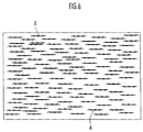
- FIG. 6 is a diagram illustrating a linear portion visible in a conventional surface illuminant equipment.
- the surface illuminant equipment 1 of the present embodiment includes a light source 3 , a reflector 5 , a light guiding plate 7 , a reflection sheet 9 , a prism sheet 11 , a dispersion sheet 13 and a frame body 15 .
- the circled portion in FIG. 1 is a partially enlarged view of the light guiding plate 7 .
- the light source 3 is a linear light source such as a cold cathode fluorescent tube, a hot cathode fluorescent tube and the others.
- a linear light source such as a cold cathode fluorescent tube, a hot cathode fluorescent tube and the others.
- the light guiding plate 7 has an external view of a square shape and is formed from a translucent material, such as an acryl resin, polycarbonate resin or the like.
- a translucent material such as an acryl resin, polycarbonate resin or the like.
- one side surface 7 a 1 (the side surface at the front side in FIG. 1 ) is set as a light incidence plane for a light ray from the light source 3 to the light guiding plate 7 .
- the light source 3 is therefore disposed opposite to the light incidence plane 7 a 1 with its longitudinal direction same as the longitudinal direction of the light incidence plane 7 a 1 .
- the reflector 5 to cover the periphery of the light source 3 .
- the source light emitted from the light source 3 is either guided directly to the light guiding plate 7 from the light incidence plane 7 a 1 or guided to the light guiding plate 7 from the light incidence plane 7 a 1 after reflected from the reflector 6 .
- a direction orthogonal to the light incidence plane 7 a 1 is set as X axial direction, and two axial directions orthogonal to each other in a plane which is orthogonal to the X axial direction as Y axial direction and Z axial direction, respectively.
- the X, Y and Z axial directions are orthogonal mutually.
- the Z axial direction is set as the width direction (vertical direction in FIG. 1 ) of the light guiding plate 7 and the Y direction is set as the longitudinal direction (the longitudinal direction of the light source 3 ) of the light incidence plane 7 a 1 .
- the X axial direction is a direction from one side surface of the light guiding plate 7 , that is, the light incidence plane 7 a 1 , toward the other side surface 7 a 2 opposite to the light incidence plane 7 a 1 , generally the guiding direction of the source light from the light source 3 to the light guiding plate 7 .
- only one side surface 7 a 1 of the light guiding plate 7 is set as the light incidence plane, it is also possible to set both the side surface 7 a 1 and the opposite side surface 7 a 2 as the light incidence plane and the source light will be guided into the light guiding plate 7 from the two side surfaces 7 a 1 and 7 a 2 .
- a front surface 7 b an upper surface in the drawings, of the light guiding plate 7 serves as a light emitting plane emitting light outside.
- the front surface 7 b is formed with, as illustrated in an encircled view in FIG. 1 and FIG. 2 , a plurality of convex strip portions 17 extending in parallel to each other in the X axial direction.
- the convex strip portions 17 are disposed in parallel with a given interval (a given pitch) substantially across the entire surface of the front surface 7 b of the light guiding plate 7 .
- a side surface of each convex strip portion 17 is provided with a plurality of concave portions 19 . A detailed description on the convex strip portions 17 and the concave portions 19 will be carried out hereinafter.
- a back surface 7 c , a lower surface in FIG. 1 , of the light guiding plate 7 is formed with a plurality of prisms 21 extending in parallel to each other in the X axial direction (same direction as the convex strip portions 17 ).
- the prisms 21 are disposed in parallel with a given interval (a given pitch) substantially across the entire surface of the back surface 7 c of the light guiding plate 7 .
- the cross section (section orthogonal to the X axial direction) of each prism 21 is substantially of a triangular shape, in other words, each prism 21 is roughly a triangular prism extending in the X axial direction.
- the prisms 21 are formed integral with the light guiding plate 7 by injection molding and the like.
- a width W 21 of each prism 21 in the Y axial direction is, for example, 23.2 ⁇ m; an interval P 21 (pitch of the array of the prisms 21 ) of the mutually adjacent prisms 21 and 21 in the Y axial direction is, for example, 29 ⁇ m.
- the prisms 21 formed on the back surface 7 c of the light guiding plate 7 as described above have the function to alter the propagation course of the source light which is guided from the light source 3 into the light guiding plate 7 and propagates in the light guiding plate 7 to the back surface 7 c of the light guiding plate 7 so as to increase the light amount (light amount reflected from the reflection sheet 9 , which will be described hereinafter) emitted to the outside of the light guiding plate 7 through the back surface 7 c.
- the reflection sheet 9 is provided for the back surface 7 c of the light guiding plate 7 to cover the entire back surface 7 c .
- the reflection sheet 9 reflects the light emitted from the back surface 7 c of the light guiding plate 7 toward the front surface 7 b of the light guiding plate 7 so as to make the light return to the light guiding plate 7 .
- the front surface 7 b of the light guiding plate 7 is provided with the prism sheet 11 overlapped with the dispersion sheet 13 to cover the entire front surface 7 b .
- the prism sheet 11 is formed from a plurality of prisms 11 a extending in parallel to each other in the Y axial direction of the prism sheet 11 on the front surface 7 b .
- the prisms 11 a are disposed in parallel with a given interval (a given pitch) in the X axial direction substantially across the entire surface of the front surface 7 b of the light guiding plate 7 .
- each prism 11 a is substantially of a triangular shape, in other words, each prism 11 a is roughly a triangular prism extending in the Y axial direction.
- a width W 11 of each prism 11 a in the X axial direction is, for example, 50 ⁇ m; an interval P 11 (pitch of the array of the prisms 11 a ) of the mutually adjacent prisms 11 a and 11 a in the X axial direction is, for example, 50 ⁇ m.
- the prism sheet 11 having the above mentioned prisms 11 a functions to adjust the propagation course of the light emitted outside from the front surface 7 b (light emitting surface) of the light guiding plate 7 so as to increase the light amount in the width direction or a direction close to the width direction of the light guiding plate 7 .
- the dispersion sheet 13 is used to disperse the light emitted by transmitting through the prism sheet 11 from the front surface 7 b of the light guiding plate 7 .
- the surface illuminant equipment 1 is constituted by assembling the reflector 5 and the light source 3 to the end of the light incidence plane 7 a 1 in a state that the reflection sheet 9 has been overlapped with the back surface 7 c of the light guiding plate 7 , and assembling the light guiding plate 7 into the frame body 15 in a state that the prism sheet 11 and the dispersion sheet 13 has been overlapped with the front surface 7 b of the light guiding plate 7 .
- FIG. 3 is a plane view illustrating a part of the front surface 7 b of the light guiding plate 7 illustrated in FIG. 2 viewed in the width direction of the light guiding plate 7 .
- each convex strip portion 17 is formed with a substantially flat top surface and an inclined side surface. Between two adjacent convex strip portions 17 and 17 , there is provided an interval 23 .
- the front surface 7 b of the light guiding plate 7 is a flat surface at the location where the interval 23 is present.
- the convex strip portions 17 are formed integral with the light guiding plate 7 by injection molding and the like.
- a width W 17 of each convex strip portion 17 in the Y axial direction is, for example, 29 ⁇ m in the present embodiment; the interval W 23 in the Y axial direction is, for example, 4 ⁇ m in the present embodiment.
- each convex strip portion 17 is formed with a plurality of concave portions 19 by concaving the side surface at a plurality of locations with an interval along the extending direction (X axial direction) of the convex portion 17 .
- each convex strip portion 17 is formed with the concave portions 19 on the two side surfaces thereof, except for the convex strip portions 17 located at two ends of the front surface 7 b in the Y axial direction.
- the convex strip portions 17 located at two ends of the front surface in the Y axial direction only the side surface close to its adjacent convex strip portion 17 is provided with the concave portions 19 .
- each concave portion 19 for each convex strip portion 17 is shaped by cutting out the side surface of the convex strip portion 17 to a substantially triangular shape toward the central axis of the convex strip portion 17 .
- an inner wall of each concave portion 19 is formed from two flat planes 19 a and 19 b crossed at the penetralia of the concave portion 19 .
- Those flat planes 19 a and 19 b are inclined (not parallel) with respect to any direction of the X, Y and Z axial directions.
- each of the flat planes 19 a and 19 b is an inclined plane having a magnitude other than zero for any of the components in the X, Y and Z axial directions of its normal line vector.
- the respective components in the X axial direction for the flat planes 19 a and 19 b of each concave portion 19 have mutually inversed directions (mutually different polarity); on the other hand, the respective components in the Y axial direction and Z axial direction for the flat planes 19 a and 19 b of each concave portion 19 have mutually same directions (mutually identical polarity).
- the respective concave portions 19 and 19 formed on the side surfaces opposite to each other in two mutually adjacent convex strip portions 17 and 17 are provided axisymmetrical with respect to the central axis (central axis extending in the X axial direction) between the two mutually adjacent convex strip portions 17 and 17 .
- the central axis central axis extending in the X axial direction
- two convex strip portions with respective reference numbers 17 m and 17 n in parenthesis representatively stand for the two mutually adjacent convex strip portions 17 and 17 , respectively.
- the concave portion 19 formed on the side surface of the convex strip portion 17 m close to the convex strip portion 17 n , and the concave portion 19 formed on the side surface of the convex strip portion 17 n close to the convex strip portion 17 m , are provided axisymmetrical with respect to the central axis C (the central axis C of the interval 23 between the convex strip portions 17 m and 17 n ), when the front surface 7 b of the light guiding plate 7 is viewed in the width direction of the light guiding plate 7 .
- one concave portion 19 of the concave portions 19 formed on the side surfaces of the convex strip portion 17 n close to the convex strip portion 17 m is opposing to each concave portion 19 formed on the side surface of the convex portion 17 m close to the convex strip portion 17 n , and a pair of mutually opposite concave portions 19 and 19 are disposed axisymmetrical with respect to the central axis C.
- the pair of mutually opposing concave portions 19 and 19 are provided plane-symmetrical with respect to the plane vertical to (parallel to the Z axis) the Y axial direction containing therein the central axis C.
- the front surface 7 b of the light guiding plate 7 has a flat portion 25 which is continuous to the interval 23 at a location between the concave portions 19 and 19 mutually opposite in the Y axial direction.
- the maximum width W 25 of the flat portion 25 between the mutually opposing concave portions 19 and 19 in the Y axial direction is, for example, 16 ⁇ m; the length L 25 of the flat portion in the X axial direction is, for example, 42 ⁇ m.
- the width W 19 of the flat planes 19 a and 19 b in each concave portion 19 in the Y axial direction is, for example, 6.5 ⁇ m; among the flat planes 19 a and 19 b , the length L 19 b of the flat plane 19 b close to the light incidence plane 7 a 1 in the X axial direction is, for example, 62.5 ⁇ m, and the length L 19 a of the flat plane 19 a close to the light incidence plane 7 a 2 in the X axial direction is, for example, 25 ⁇ m.
- the concave portions 19 are disposed loosely when it is closer to the light incidence plane 7 a 1 of the light guiding plate 7 in the X axial direction; while the concave portions 19 are disposed densely when it is farther away from the light incidence plane 7 a 1 of the light guiding plate 7 in the X axial direction.
- FIG. 4 is a cross-sectional view of the liquid crystal display.
- the convex strip portions 17 and the prisms 21 of the light guiding plate 7 and the prisms 11 a of the prism sheet 11 are omitted in FIG. 4 .
- the display apparatus 31 includes the surface illuminant equipment 1 described in the above, the liquid crystal display (liquid crystal cell) 33 , a driver board 35 which is a driving circuit board for the liquid crystal display 33 , and a frame-shaped bezel 37 to cover the outside of the liquid crystal 33 and the surface illuminant equipment 1 .
- the surface illuminant equipment 1 is constituted by assembling the reflector 5 and the light source 3 to the end of the light incidence plane 7 a 1 in a state that the reflection sheet 9 has been overlapped with the back surface 7 c of the light guiding plate 7 , and assembling the light guiding plate 7 into the frame body 15 in a state that the prism sheet 11 and the dispersion sheet 13 has been overlapped with the front surface 7 a of the light guiding plate 7 .
- the front surface 7 b of the light guiding plate 7 of the surface illuminant equipment 1 is provided with the liquid crystal display 33 interposed therebetween with the prism sheet 11 and the dispersion sheet 13 .
- the surface illuminant equipment 1 and the liquid crystal display 33 are held by the bezel 37 attached outside thereof.
- the back surface 7 c of the light guiding plate 7 is provided with the driver board 35 interposed therebetween with the reflection sheet 9 .
- the driver board 35 is located close to the side surface 7 a 2 opposing to the light incidence plane 7 a 1 of the light guiding plate 7 and attached to the frame body 15 of the surface illuminant equipment 1 . Further, the driver board 35 is connected with the liquid crystal display 33 via a signal line 39 wired between the frame 15 and the bezel 37 .
- the driver board 35 is connected via a connector 43 with a signal line 41 for supplying power to and/or controlling a driving circuit (not shown) mounted thereon.
- the signal line 41 is wired at the back surface side of the light guiding plate 7 along the reflection sheet 9 .
- each concave portion 19 functions as the dot in the conventional surface illuminant equipment.
- the flat planes 19 a and 19 b are inclined with respect to the X, Y and Z axial directions, respectively.
- the light reflected from the flat planes 19 a and 19 b constituting the inner wall of each concave portion 19 is easy to propagate in a direction sufficiently inclined with respect to the width direction (Z axial direction) of the light guiding plate 7 .
- the edge of the inner wall of each concave portion 19 (the intersection of the flat planes 19 a and 19 b , or the boundary of each of the flat planes 19 a and 19 b ) has roundness, the light entered to the edge is easy to propagate in a direction sufficiently inclined with respect to the width direction (Z axial direction) of the light guiding plate 7 .
- the light reflected from or dispersed by the inner wall (the flat planes 19 a and 19 b ) or the edge of the inner wall is prevented from concentrating on the axis of the width direction of the light guiding plate 7 or a direction close to the width direction thereof. Furthermore, in the prism sheet 11 , it is easy for the light whose propagation course is altered to the width direction or a direction close to the width direction of the light guiding plate 7 to be emitted from the front surface 7 b of the light guiding plate 7 .
- the dotted portion with relatively high luminance is prevented from occurring at each concave portion 19 when the front surface 7 b of the light guiding plate 7 is viewed directly from the width direction of the light guiding plate 7 . Consequently, the linear portion with relatively low luminance as illustrated in FIG. 6 described above is also prevented from occurring when the front surface 7 b of the light guiding plate 7 is viewed via the prism sheet 11 .
- the display apparatus 31 is capable for the display apparatus 31 to prevent displaying irregularity in the image displayed on the liquid crystal display 33 .
- the prism sheet 11 Since the incident amount of the light whose propagation course has been altered to the width direction or a direction close to the width direction of the light guiding plate 7 (incident amount of light from the light guiding plate 7 to the prism sheet 11 ) is increased in the prism sheet 11 , the prism sheet 11 is capable of improving the average luminance of light emitted from the front surface of the light guiding plate 7 through the prism sheet 11 and the dispersion sheet 13 .
- the average luminance for the front surface 7 b of the light guiding plate 7 is obtained at about 5864 cd/m 2 experimentally.
- the average luminance on the front surface of the light guiding plate is about 5219 cd/m 2 .
- the average luminance of the front surface of the light guiding plate in the surface illuminant equipment 1 of the present embodiment has been improved by at least 600 cd/m 2 , compared with that in the conventional surface illuminant equipment.
- each of the convex strip portions 17 formed on the side surfaces of the concave portions 19 which serves as the dot being pushed toward the liquid crystal display 33 via the prism sheet 11 and the dispersion sheet 13 , is not a dotted one but linearly extended portions, thus, the acting force centered on the convex strip portion 17 locally can be avoided. As a result, damage to the convex strip portion 17 or the concave portions 19 formed thereon can be prevented.
- the concave portions 19 and 19 formed on the respective side surfaces opposing to each other of the mutually adjacent convex strip portions 17 and 17 are provided axisymmetrical with respect to the central axis between the convex strip portions 17 and 17 , however, it is not necessary.
- FIG. 5 is a plane view of the front surface 7 b of the light guiding plate 7 viewed in Z axial direction.
- each concave portion 19 is constituted from two flat planes 19 a and 19 b , however, it is possible for it to be formed from three or more than three flat planes.
- the convex strip portions 17 are provided on the front surface 7 b of the light guiding plate 7 , however, it is possible to provide the convex strip portions 17 on the back surface 7 c thereof. In this case, it is possible to form a plurality of prisms on the front surface of the light guiding plate 7 , or form the front surface to a mirror shape.
- the width of the light guiding plate 7 is configured as constant, however, it is also possible to form the light guiding plate 7 in such a way that the width is gradually decreased from the light incidence plane 7 a 1 toward the opposite side surface 7 a 2 of the light guiding plate 7 .
Landscapes
- Physics & Mathematics (AREA)
- General Physics & Mathematics (AREA)
- Optics & Photonics (AREA)
- Nonlinear Science (AREA)
- Mathematical Physics (AREA)
- Chemical & Material Sciences (AREA)
- Crystallography & Structural Chemistry (AREA)
- Planar Illumination Modules (AREA)
- Light Guides In General And Applications Therefor (AREA)
- Optical Elements Other Than Lenses (AREA)
- Liquid Crystal (AREA)
Applications Claiming Priority (2)
| Application Number | Priority Date | Filing Date | Title |
|---|---|---|---|
| JP2007110504A JP4840779B2 (ja) | 2007-04-19 | 2007-04-19 | 面光源装置 |
| JP2007-110504 | 2007-04-19 |
Publications (2)
| Publication Number | Publication Date |
|---|---|
| US20080259644A1 US20080259644A1 (en) | 2008-10-23 |
| US7780331B2 true US7780331B2 (en) | 2010-08-24 |
Family
ID=39872005
Family Applications (1)
| Application Number | Title | Priority Date | Filing Date |
|---|---|---|---|
| US12/104,868 Active 2029-02-27 US7780331B2 (en) | 2007-04-19 | 2008-04-17 | Surface illuminant equipment |
Country Status (4)
| Country | Link |
|---|---|
| US (1) | US7780331B2 (ja) |
| JP (1) | JP4840779B2 (ja) |
| KR (1) | KR101407010B1 (ja) |
| TW (1) | TWI420052B (ja) |
Cited By (2)
| Publication number | Priority date | Publication date | Assignee | Title |
|---|---|---|---|---|
| US20100097825A1 (en) * | 2008-10-17 | 2010-04-22 | Chao-Hung Weng | Light Guide Plate |
| US8764264B2 (en) | 2011-10-11 | 2014-07-01 | GE Lighting Solutions, LLC | Edge-lit luminaire |
Families Citing this family (5)
| Publication number | Priority date | Publication date | Assignee | Title |
|---|---|---|---|---|
| TW201124778A (en) * | 2009-10-09 | 2011-07-16 | Mitsubishi Rayon Co | Image display device |
| CN101761837A (zh) * | 2010-02-11 | 2010-06-30 | 陈晓锋 | 一种新型墙地灯 |
| JP5646280B2 (ja) * | 2010-10-28 | 2014-12-24 | スタンレー電気株式会社 | 面光源装置 |
| KR101866244B1 (ko) | 2011-01-17 | 2018-06-12 | 삼성전자주식회사 | 스캐닝 백라이트 유닛 및 이를 구비하는 액정 표시 장치 |
| KR101830718B1 (ko) * | 2011-07-15 | 2018-02-22 | 엘지이노텍 주식회사 | 디스플레이 장치 |
Citations (6)
| Publication number | Priority date | Publication date | Assignee | Title |
|---|---|---|---|---|
| JPH05203947A (ja) | 1992-01-24 | 1993-08-13 | Stanley Electric Co Ltd | 面状発光体装置 |
| JP2000221329A (ja) | 1999-01-29 | 2000-08-11 | Stanley Electric Co Ltd | 面光源装置 |
| US6277471B1 (en) * | 1999-06-18 | 2001-08-21 | Shih Chieh Tang | Brightness enhancement film |
| US6811274B2 (en) * | 2002-12-04 | 2004-11-02 | General Electric Company | Polarization sensitive optical substrate |
| US20070010594A1 (en) * | 2005-06-09 | 2007-01-11 | Ubright Optronics Corporation | Moire reducing optical substrates with irregular prism structures |
| US20070047254A1 (en) * | 2005-08-27 | 2007-03-01 | 3M Innovative Properties Company | Illumination assembly and system |
Family Cites Families (7)
| Publication number | Priority date | Publication date | Assignee | Title |
|---|---|---|---|---|
| JPH1124586A (ja) * | 1997-06-30 | 1999-01-29 | Sanyo Electric Co Ltd | バックライト装置及び導光板 |
| JP2000260215A (ja) * | 1999-03-05 | 2000-09-22 | Seiko Epson Corp | 照明装置及び導光システム |
| JP2002182038A (ja) * | 2000-12-14 | 2002-06-26 | Nagano Kogaku Kenkyusho:Kk | 導光板およびバックライトシステム |
| US7581868B2 (en) * | 2004-06-16 | 2009-09-01 | Samsung Electronics Co., Ltd. | Backlight assembly and liquid crystal display apparatus having the same |
| TW200615660A (en) * | 2004-09-13 | 2006-05-16 | Wooyoung Co Ltd | Light guide panel for backlight unit, lower main core for molding bottom surface of light guide panel, and method of manufacturing light guide panel using lower main core |
| KR20080021043A (ko) * | 2005-06-24 | 2008-03-06 | 이데미쓰 고산 가부시키가이샤 | 광확산판 및 그것을 이용한 조명 장치 |
| US7744235B2 (en) * | 2005-06-29 | 2010-06-29 | Kuraray Co., Ltd. | Lighting device and light control member used therefor and image display device using the lighting device and the light control member |
-
2007
- 2007-04-19 JP JP2007110504A patent/JP4840779B2/ja not_active Expired - Fee Related
-
2008
- 2008-04-17 KR KR1020080035498A patent/KR101407010B1/ko not_active Expired - Fee Related
- 2008-04-17 TW TW097113969A patent/TWI420052B/zh not_active IP Right Cessation
- 2008-04-17 US US12/104,868 patent/US7780331B2/en active Active
Patent Citations (6)
| Publication number | Priority date | Publication date | Assignee | Title |
|---|---|---|---|---|
| JPH05203947A (ja) | 1992-01-24 | 1993-08-13 | Stanley Electric Co Ltd | 面状発光体装置 |
| JP2000221329A (ja) | 1999-01-29 | 2000-08-11 | Stanley Electric Co Ltd | 面光源装置 |
| US6277471B1 (en) * | 1999-06-18 | 2001-08-21 | Shih Chieh Tang | Brightness enhancement film |
| US6811274B2 (en) * | 2002-12-04 | 2004-11-02 | General Electric Company | Polarization sensitive optical substrate |
| US20070010594A1 (en) * | 2005-06-09 | 2007-01-11 | Ubright Optronics Corporation | Moire reducing optical substrates with irregular prism structures |
| US20070047254A1 (en) * | 2005-08-27 | 2007-03-01 | 3M Innovative Properties Company | Illumination assembly and system |
Cited By (3)
| Publication number | Priority date | Publication date | Assignee | Title |
|---|---|---|---|---|
| US20100097825A1 (en) * | 2008-10-17 | 2010-04-22 | Chao-Hung Weng | Light Guide Plate |
| US8333497B2 (en) * | 2008-10-17 | 2012-12-18 | Coretronic Corporation | Light guide plate having micro structures arranged in geometric and stripe patterns |
| US8764264B2 (en) | 2011-10-11 | 2014-07-01 | GE Lighting Solutions, LLC | Edge-lit luminaire |
Also Published As
| Publication number | Publication date |
|---|---|
| JP4840779B2 (ja) | 2011-12-21 |
| KR101407010B1 (ko) | 2014-06-13 |
| JP2008269922A (ja) | 2008-11-06 |
| TW200902913A (en) | 2009-01-16 |
| US20080259644A1 (en) | 2008-10-23 |
| TWI420052B (zh) | 2013-12-21 |
| KR20080094583A (ko) | 2008-10-23 |
Similar Documents
| Publication | Publication Date | Title |
|---|---|---|
| JP4351534B2 (ja) | プリズムシート、該プリズムシートを使用したバックライト・ユニットおよび透過型液晶表示装置 | |
| US6752504B2 (en) | Illumination device and reflection type liquid crystal display device using the same | |
| US7780331B2 (en) | Surface illuminant equipment | |
| US9291852B2 (en) | Display apparatus | |
| CN101994995B (zh) | 导光板及具备该导光板的背光源装置 | |
| US20160103264A1 (en) | Backlight unit and display apparatus having the same | |
| JP5254658B2 (ja) | 面光源装置 | |
| US7356211B2 (en) | Lighting system | |
| KR20030096509A (ko) | 프리즘 시트 및 이를 갖는 액정표시기 | |
| JPWO2007066729A1 (ja) | 面発光装置及び液晶表示装置 | |
| JP4423933B2 (ja) | 光学シートとそれを用いたバックライトユニットおよびディスプレイ | |
| CN111999794B (zh) | 显示装置 | |
| KR20060061257A (ko) | 면광원 장치 및 표시장치 | |
| JP5533310B2 (ja) | 導光板、面光源装置および表示装置 | |
| KR20060051190A (ko) | 액정표시장치 백라이트 유닛용 도광판 및 이를 이용한액정표시장치용 백라이트 유닛 | |
| JP3932544B2 (ja) | 面光源装置 | |
| JP2018041717A (ja) | 面光源装置および表示装置 | |
| WO2011108294A1 (ja) | 導光板、照明装置、および表示装置 | |
| CN218064734U (zh) | 背光模组及显示装置 | |
| US7527407B2 (en) | Optic film and backlight module using same | |
| JP5929552B2 (ja) | 導光板、面光源装置、透過型表示装置 | |
| WO2012099123A1 (ja) | 導光板、面光源装置及び透過型画像表示装置 | |
| US7978410B2 (en) | Optical sheet | |
| EP3635292B1 (en) | Display apparatus | |
| US7864265B2 (en) | Lamp holder, and backlight device and liquid crystal display device using such lamp holder |
Legal Events
| Date | Code | Title | Description |
|---|---|---|---|
| AS | Assignment |
Owner name: STANLEY ELECTRIC CO., LTD., JAPAN Free format text: ASSIGNMENT OF ASSIGNORS INTEREST;ASSIGNOR:OHMORI, ATSUSHI;REEL/FRAME:020825/0957 Effective date: 20080314 |
|
| STCF | Information on status: patent grant |
Free format text: PATENTED CASE |
|
| FEPP | Fee payment procedure |
Free format text: PAYOR NUMBER ASSIGNED (ORIGINAL EVENT CODE: ASPN); ENTITY STATUS OF PATENT OWNER: LARGE ENTITY |
|
| FPAY | Fee payment |
Year of fee payment: 4 |
|
| MAFP | Maintenance fee payment |
Free format text: PAYMENT OF MAINTENANCE FEE, 8TH YEAR, LARGE ENTITY (ORIGINAL EVENT CODE: M1552) Year of fee payment: 8 |
|
| MAFP | Maintenance fee payment |
Free format text: PAYMENT OF MAINTENANCE FEE, 12TH YEAR, LARGE ENTITY (ORIGINAL EVENT CODE: M1553); ENTITY STATUS OF PATENT OWNER: LARGE ENTITY Year of fee payment: 12 |