US7775433B2 - Optical deflection apparatus, image forming apparatus, and method of driving optical deflection apparatus - Google Patents
Optical deflection apparatus, image forming apparatus, and method of driving optical deflection apparatus Download PDFInfo
- Publication number
- US7775433B2 US7775433B2 US12/048,675 US4867508A US7775433B2 US 7775433 B2 US7775433 B2 US 7775433B2 US 4867508 A US4867508 A US 4867508A US 7775433 B2 US7775433 B2 US 7775433B2
- Authority
- US
- United States
- Prior art keywords
- time
- deflection
- driving
- optical deflector
- optical
- Prior art date
- Legal status (The legal status is an assumption and is not a legal conclusion. Google has not performed a legal analysis and makes no representation as to the accuracy of the status listed.)
- Expired - Fee Related, expires
Links
Images


Classifications
-
- G—PHYSICS
- G02—OPTICS
- G02B—OPTICAL ELEMENTS, SYSTEMS OR APPARATUS
- G02B26/00—Optical devices or arrangements for the control of light using movable or deformable optical elements
- G02B26/08—Optical devices or arrangements for the control of light using movable or deformable optical elements for controlling the direction of light
- G02B26/10—Scanning systems
- G02B26/105—Scanning systems with one or more pivoting mirrors or galvano-mirrors
-
- G—PHYSICS
- G02—OPTICS
- G02B—OPTICAL ELEMENTS, SYSTEMS OR APPARATUS
- G02B26/00—Optical devices or arrangements for the control of light using movable or deformable optical elements
- G02B26/08—Optical devices or arrangements for the control of light using movable or deformable optical elements for controlling the direction of light
- G02B26/0816—Optical devices or arrangements for the control of light using movable or deformable optical elements for controlling the direction of light by means of one or more reflecting elements
- G02B26/0833—Optical devices or arrangements for the control of light using movable or deformable optical elements for controlling the direction of light by means of one or more reflecting elements the reflecting element being a micromechanical device, e.g. a MEMS mirror, DMD
- G02B26/085—Optical devices or arrangements for the control of light using movable or deformable optical elements for controlling the direction of light by means of one or more reflecting elements the reflecting element being a micromechanical device, e.g. a MEMS mirror, DMD the reflecting means being moved or deformed by electromagnetic means
-
- G—PHYSICS
- G02—OPTICS
- G02B—OPTICAL ELEMENTS, SYSTEMS OR APPARATUS
- G02B7/00—Mountings, adjusting means, or light-tight connections, for optical elements
- G02B7/18—Mountings, adjusting means, or light-tight connections, for optical elements for prisms; for mirrors
- G02B7/182—Mountings, adjusting means, or light-tight connections, for optical elements for prisms; for mirrors for mirrors
- G02B7/1821—Mountings, adjusting means, or light-tight connections, for optical elements for prisms; for mirrors for mirrors for rotating or oscillating mirrors
Definitions
- the present invention relates to an optical deflection apparatus including a microstructure, a method of driving an optical deflection apparatus, and an image forming apparatus including an optical deflection apparatus, such as a laser beam printer.
- optical deflection apparatuses that perform scanning with light beams are used in image forming apparatuses such as optical disc readers, barcode readers, laser beam printers, and digital copying machines.
- resonant optical deflection apparatuses have been proposed, in which typically micromirrors formed by silicon micromachining techniques are driven by resonance.
- a resonant optical deflection apparatus can be constructed in a much smaller size when compared with an optical deflection apparatus in which a rotary multiple-face mirror such as a polygon mirror is used. Furthermore, the resonant optical deflection apparatus is advantageous in that power consumption is small, face tangle does not occur theoretically, and in the case of an optical deflection apparatus formed of Si monocrystal, manufactured by semiconductor processes, metal fatigue does not occur theoretically so that durability is excellent.
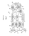
- FIG. 7 shows a micromirror that is driven according to a triangular wave.
- An optical deflection apparatus 12 includes oscillators 14 and 16 , torsion springs 18 and 20 , drivers 23 and 50 , detectors 15 and 32 , and a control circuit 30 .
- This micromirror has a fundamental resonant frequency and a resonant frequency that is substantially triple the fundamental resonant frequency, and is driven according to a combined frequency of the fundamental resonant frequency and the substantially triple resonant frequency.
- the oscillator 14 having a mirror surface is driven according to a triangular wave, so that the deflection angle has less change in the angular velocity compared with a case of driving according to a sine wave.
- vibration of the oscillator 14 is detected by the detectors 15 and 32 , the control circuit 30 generates a driving signal needed to generate a triangular wave, and drivers 23 and 50 drive the micromirror.
- International Publication No. WO2005/063613 discloses a micro oscillator in which a system including a plurality of torsion springs and a plurality of movable members have a plurality of separate natural vibration modes.
- the plurality of separate natural vibration modes includes a reference vibration mode, which is a natural vibration mode at a reference frequency, and an even-multiple vibration mode, which is a natural vibration mode at frequency that is substantially an even-integer multiple of the reference frequency.
- driving according to a sawtooth wave is achieved by causing the micro oscillator to vibrate in these oscillation modes.
- the resonant frequency of a resonant optical deflector is determined according to the mass of an oscillator and the spring constant of a torsion spring in the optical deflector. Since the spring constant of the torsion spring changes depending on environmental factors such as temperature, the resonant frequency of the resonant optical deflector also changes depending on environmental factors.
- a heat generator is provided in an optical deflector to heat a torsion spring and thereby adjust the resonant frequency.
- control of the deflection angle is an important issue in a case where the resonant frequency of an optical deflector changes due to environmental factors.
- an optical deflection apparatus can be precisely controlled even if the resonant frequency of an optical deflector changes.
- An optical deflection apparatus includes a light source configured to generate a light beam; an optical deflector including a first oscillator, a second oscillator, a first torsion spring, and a second torsion spring, the first torsion spring connecting the first oscillator and the second oscillator, the second torsion spring being connected to the second oscillator, and the first and second torsion springs sharing a common torsion axis; a driver configured to apply a driving force to the optical deflector; and a driving controller configured to supply a driving signal to the driver.
- the driving controller is configured to set a reference frequency of the driving signal for driving the optical deflector on the basis of a resonant frequency of the optical deflector, to calculate a target time at which one of the first and second oscillators makes a predetermined deflection angle on the basis of the reference frequency, and to supply such a driving signal that the one of the first and second oscillators passes through a point corresponding to the predetermined deflection angle at the target time.
- An image forming apparatus includes the optical deflection apparatus configured as described above; an optical system; and a photosensitive body.
- the optical deflector performs scanning using the light beam generated by the light source, and the optical system condenses scanning line at a target position on the photosensitive body.
- a method of driving an optical deflection apparatus including an optical deflector having a plurality of natural vibration modes includes the steps of measuring a resonant frequency of the optical deflector; setting a reference frequency for driving the optical deflector on the basis of the resonant frequency that has been measured; setting a target time at which deflected light deflected by the optical deflector makes a predetermined deflection angle on the basis of the reference frequency that has been set; measuring a time at which the optical deflector makes the predetermined angle; and determining a driving signal for driving the optical deflector on the basis of the target time that has been set and time information representing the time that has been measured.
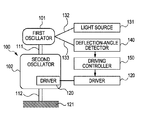
- FIG. 1 is a block diagram of an optical deflection apparatus according to the present invention.
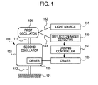
- FIGS. 2A to 2C are diagrams showing an arrangement of photodetector elements in the optical deflection apparatus according to the present invention.
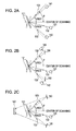
- FIGS. 3A and 3B are diagrams showing an example of an optical deflector according to the present invention.
- FIGS. 4A is a diagram showing relationship between the deflection angle of the optical deflection apparatus according to the present invention and temporal change
- FIG. 4B is a diagram showing a region of substantially constant angular velocity of the optical deflection apparatus according to the present invention.
- FIG. 5 is a block diagram relating to control of the optical deflection apparatus according to the present invention.
- FIG. 6 is an illustration of an image forming apparatus according to the present invention.
- FIG. 7 is a diagram showing an optical deflector according to the related art.
- FIG. 1 is a block diagram of an optical deflection apparatus according to the present invention.
- An optical deflector 100 includes a first oscillator 101 , a second oscillator 102 , a first torsion spring 111 connecting the first oscillator 101 and the second oscillator 102 , and a second torsion spring 112 connected to the second oscillator 102 and sharing a common torsion axis with the first torsion spring 111 .
- a driver 120 is configured so that it can apply a driving force to the optical deflector 100 , such as an electromagnetic force, an electrostatic force, a piezoelectric force.
- a driving force such as an electromagnetic force, an electrostatic force, a piezoelectric force.
- one part of the driver 120 is provided in the second oscillator 102 and another part of the driver 120 is provided in the proximity thereof. These parts of the driver 120 cooperate to apply a driving force to the second oscillator 102 .
- the arrangement may be such that a magnet is provided in the second oscillator 102 and a coil is provided at such a distance that a driving force can be applied to the magnet.
- the arrangement may be such that a coil is provided in the second oscillator 102 and a magnet is provided in the proximity thereof.
- the driver 120 is provided in association with the second oscillator 102 , according to the present invention, the driver 120 may be provided in association with the first oscillator 101 .
- the first oscillator 101 has a reflection mirror on the surface thereof so that the first oscillator 101 deflects a light beam 132 transmitted from a light source 131 .
- a deflected light 133 deflected by the optical deflector 100 is received by a deflection-angle detector 140 having photodetector elements, and outputs corresponding timing information to a driving controller 150 .
- the driving controller 150 generates a driving signal for driving the optical deflector 100 , and supplies the driving signal to the driver 120 .
- the driving controller 150 sets a reference frequency of the driving signal for driving the optical deflector 100 , calculates a target time at which one of the first and second oscillators 101 and 102 make a predetermined deflection angle on the basis of the reference frequency, and supplies such a driving signal that the one of the first and second oscillators 101 and 102 passes through a point corresponding to the predetermined deflection angle.
- An optical deflector 100 includes the two oscillators 101 and 102 and the two torsion springs 111 and 112 as shown in FIG. 1 .
- I k denotes the moment of inertia of a k-th oscillator
- k k denotes the spring constant of a k-th torsion spring
- the oscillators can be caused to perform various movements.
- the expression “integer multiple” should be construed to cover “substantially integer multiple”, i.e., a range of values of approximately 0.98 n to 1.02 n (n is an arbitrarily chosen integer) times the fundamental frequency.
- the optical deflector by configuring the optical deflector according to this embodiment so that two oscillators and two torsion springs are provided and a fundamental frequency and a frequency that is substantially double the fundamental frequency in the angular frequencies ⁇ k , it is possible to drive the optical deflector at a substantially constant angular velocity with little variation in the angular velocity of the oscillators in a predetermined range. More specifically, the optical deflector is driven according to a combined wave A 1 sin ⁇ t+A 2 sin(2 ⁇ t+ ⁇ ) of a sine wave A 1 sin ⁇ t having the fundamental frequency and a sine wave A 2 sin(2 ⁇ t+ ⁇ ) having a frequency that is double the fundamental frequency, as shown in FIG. 4A . Then, as shown in FIG. 4B , a region of angular velocity in which the optical deflector is driven at a substantially constant angular velocity is increased compared with a case where the optical deflector is driven according to the sine wave A 1 sin ⁇ t.
- FIGS. 3A and 3B show a specific example configuration of the optical deflection apparatus according to the present invention.
- FIG. 3A is a top view of an optical deflector.
- a plate member 300 is manufactured by etching a silicon wafer.
- An oscillator 301 having a plate shape is supported by two torsion springs 311 a and 311 b at its top and bottom as viewed in FIG. 3A .
- On a top surface of the oscillator 301 a light reflecting film is formed.
- An oscillator 302 having a frame shape supports the torsion springs 311 a and 311 b inside thereof, and is supported by two torsion springs 312 a and 312 b at its top and bottom as viewed in FIG. 3A .
- a supporting frame supports the torsion springs 312 a and 312 b inside thereof.
- the torsion springs 311 a , 311 b , 312 a , and 312 b share the same torsion axis.
- the oscillators 301 and 302 and the torsion springs 311 a , 311 b , 312 a , and 312 b have two vibration modes according to the principles described earlier, and are adjusted so that the frequency in one of the modes is substantially double the frequency in the other mode.
- FIG. 3B is a schematic diagram for explaining a driver of the optical deflection apparatus.
- the plate member 300 is shown in section taken along a line IIIB-IIIB in FIG. 3A .
- a permanent magnet 341 is bonded on a bottom surface of the oscillator 302 .
- the plate member 300 is bonded to a yoke 344 formed of a material having a high magnetic permeability.
- a core 343 formed of a material having a high magnetic permeability is provided, and a coil 342 is wound around the core 343 .
- the permanent magnet 341 , the coil 342 , the core 343 , and the yoke 344 form an electromagnetic actuator 340 .
- a current is caused to flow through the coil 342 , a torque is applied to the permanent magnet 341 , whereby the oscillators 301 and 302 are driven.
- the oscillator 101 has a reflection mirror on the surface thereof so that the oscillator 101 deflects the light beam 132 transmitted from the light source 131 .
- first and second photodetector elements 141 and 142 may be provided at positions corresponding to first and second deflection angles, as shown in FIG. 2A .
- reflecting members 160 may be provided at positions corresponding to first and second deflecting angles so that light reflected by the individual reflecting members 160 is received by the first and second photodetector elements 141 and 142 .
- reflecting members 160 may be provided at positions corresponding to first and second deflection angles so that light reflected by the individual reflecting members 160 is received by a single photodetector element 143 .
- the photodetector element 143 is provided opposite to the light source 131 across the oscillator 101 .
- times at which scanning light passes through points corresponding to the first and second deflecting angles are measured in this embodiment, without limitation, times at which scanning light passes through positions corresponding to a larger number of deflection angles may be measured.
- piezoelectric resistors are provided at the torsion springs 111 and 112 , and a time at which the oscillator makes a certain deflection angle is detected on the basis of signals output from the piezoelectric resistors.
- the piezoelectric resistors can be manufactured, for example, by diffusing phosphorus in p-type monocrystalline silicon. The piezoelectric resistors output signals according to torsion angles of the torsion springs 111 and 112 .
- Time information representing a time at which the oscillator makes a predetermined deflection angle, detected by the arrangement described above, is output to the driving controller 150 .
- the driving controller 150 sets a reference frequency of driving signals on the basis of the resonant frequency of the optical deflector 100 .
- the reference frequency is the resonant frequency of the optical deflector 100 .
- the reference frequency may be chosen to have a value somewhat different from the peak of the resonant frequency of the optical deflector 100 if this allows sufficiently efficient operation of the optical deflector 100 .
- the resonant frequency of the optical deflector 100 is determined according to the moment of inertia of the oscillators 101 and 102 and the spring constants of the torsion springs 111 and 112 . Furthermore, the resonant frequency of the optical deflector 100 changes depending on factors such as temperature.
- an optical deflector on the basis of an estimated range of resonant frequency.
- an ambient temperature vs. resonant frequency table for the optical deflector 100 is provided so that a resonant frequency can be determined with reference to the table by measuring the temperature of the optical deflector 100 .
- this table is stored in the driving controller 150 and a temperature sensor is provided in the proximity of the optical deflector so that the driving controller 150 can obtain information representing the resonant frequency.
- the optical deflector 100 may be driven at frequencies in a range having a certain width so that the resonant frequency can be determined on the basis of relationship between driving frequencies and displacements in the operation (i.e., the frequency associated with a maximum displacement is determined as the resonant frequency).
- the resonant frequency may be determined on the basis of attenuation in the operation of the optical deflector 100 by deactivating the optical deflector 100 after it is driven.
- the resonant frequency can be measured on the basis of a counter electromotive force of a driving coil.
- a resonant-frequency measurement unit (not shown) may be provided separately.
- the driving controller 150 calculates a target time at which one of the oscillators makes a predetermined deflection angle.
- the controller 150 sets such a target time that a large region of substantially constant angular velocity can be achieved at the driving frequency as shown in FIG. 4B .
- the driving controller 150 supplies such a driving signal to the driver 120 that the one of the oscillators passes through a point corresponding to the predetermined deflection angle at the target time.
- the displacement of the one of the oscillators can be expressed by a mathematical expression at least including a term A 1 sin ⁇ t+A 2 sin(n ⁇ t+ ⁇ ), where A 1 and A 2 denote amplitudes, ⁇ denotes a relative phase difference, ⁇ denotes the angular frequency, t denotes time, and n is an integer greater than or equal to two.
- the driving controller 150 can determine a driving signal according to the target time calculated on the basis of the reference frequency and according to time information representing the time at which the oscillator makes the predetermined deflection angle. That is, by comparing a target time calculated on the basis of the reference frequency with the time information representing the time at which the oscillator makes the predetermined deflection angle, detected before changing the driving signal, the driving controller 150 can determine a driving signal for driving the optical deflector according to the target time.
- the driving controller 150 can supply such a driving signal that A 1 , A 2 , and ⁇ in the mathematical expression at least including the term A 1 sin ⁇ t+A 2 sin(n ⁇ t+ ⁇ ) have predetermined values.
- the deflection-angle detector can detect first and second times at which the one of the oscillators makes the first deflection angle, the first and second times being different from each other, and third and fourth times at which the one of the oscillators makes the second deflection angle, the third and fourth times being different from each other.
- the driving controller 150 can set a reference frequency of driving signals on the basis of the resonant frequency of the optical deflector 100 , and calculate target times for the first to fourth times on the basis of the reference frequency. Then, the driving controller 150 supplies such a driving signal to the driver 120 that the one of the oscillators is driven according to the target times.
- the driving controller 150 can set a reference frequency for driving signals on the basis of the resonant frequency of the optical deflector, and calculate target times for ⁇ t 2 , ⁇ t 3 , and ⁇ t 4 on the basis of the reference frequency. Then, the driving controller 150 supplies such a driving signal to the driver 120 that the one of the oscillators is driven according to the target times for ⁇ t 2 , ⁇ t 3 , and ⁇ t 4 .
- the optical deflection apparatus according to the present invention is configured as described above, and is driven and controlled according to the following procedure.
- the resonant frequency of the optical deflector 100 is measured by a resonant-frequency measurement circuit 490 .
- a reference frequency is set on the basis of the resonant frequency, and target times at which light deflected by the optical deflector 100 make predetermined deflection angles are set on the basis of the reference frequency.
- the target times are calculated by a controller 400 , and the target times 410 , 411 , and 412 are set in registers.
- a time-measurement unit 420 measures times at which the optical deflector 100 being driven makes the predetermined deflection angles on the basis of outputs of the first and second photodetector elements 141 and 142 . Time information representing the measured times are stored as detected times 421 , 422 , and 423 .
- a driving signal for driving the optical deflector 100 is determined on the basis of the target times 410 , 411 , and 412 and the time information representing the times at which the optical deflector 100 makes the predetermined deflection angles (detected times 421 , 422 , and 423 ).
- the driving signal can be determined on the basis of the differences between the target times 410 , 411 , and 412 and the detected times 421 , 422 , and 423 .
- the driving signal determined in this manner is supplied to the driver 120 so that the optical deflection apparatus is driven according to the driving signal.
- optical deflection apparatus according to a first example of the present invention will be described.
- the optical deflection apparatus according to the first example is configured the same as shown in the block diagram of FIG. 1 .
- two photodetector elements are provided in a deflection-angle detector, which are arranged as shown in FIG. 2A .
- An optical deflector 100 used in the first example is configured the same as that shown in FIGS. 3A and 3B .
- the optical deflector 300 including the oscillators 301 and 302 and the torsion springs 311 and 312 have two vibration modes, with the frequency in one of the vibration modes being substantially double the frequency in the other mode.
- the moments of inertia of the oscillators 301 and 302 be denoted by I 1 and I 2
- the spring constant of the set of torsion springs 311 a and 311 b be denoted by k 1
- the spring constant of the set of torsion springs 312 a and 312 b be denoted by k 2 .
- the deflection angle ⁇ and angular velocity ⁇ ′ of the optical deflection apparatus change in time as shown in FIGS. 4A and 4B .
- the deflection angle ⁇ represented by a solid line in FIG. 4A becomes closer to a sawtooth wave than a sine wave (represented by a broken line), and the angular velocity ⁇ ′ has less amount of change in the region of substantially constant angular velocity than that of a sine wave (represented by a broken line).
- the units of values along the vertical axes in FIGS. 4A and 4B are arbitrarily chosen.
- the values of A 1 , A 2 , ⁇ , ⁇ 1 , and ⁇ 2 may be other values as long as the amount of change in the angular velocity ⁇ ′ is less than that of a sine wave in the region of substantially constant angular velocity. It is desired that, in a continuous period having a length of 20% or longer in one cycle based on the first frequency, the maximum value and minimum value of the angular velocity ⁇ ′ of the reflection mirror satisfies a relationship of (maximum value ⁇ minimum value)/(maximum value+minimum value) ⁇ 0.1.
- the first and second photoreceptors 141 and 142 are provided at positions corresponding to the deflection angle ⁇ having a value of 0.8 (A 1 ⁇ 0.8 assuming that the maximum deflection angle is 1), symmetrically with respect to the center of scanning of the optical deflection apparatus.
- t 10 is used as a reference time.
- target times (t 20 ⁇ t 10 ), (t 30 ⁇ t 10 ), and (t 40 ⁇ t 10 ) are 0.102 msec, 0.294 msec, and 0.396 msec, respectively.
- the deflection angle ⁇ and angular velocity ⁇ ′ of the optical deflector 100 changes in time as shown in FIGS. 4A and 4B .
- the deflection angle ⁇ becomes closer to a sawtooth wave than a sine wave, and the angular velocity ⁇ ′ has less amount of change in the region of substantially constant angular velocity than a sine wave.
- the deflection angle ⁇ of the optical scanner can be controlled as shown in FIGS. 4A by exercising control so that three detected times (t 2 ⁇ t 1 ), (t 3 ⁇ t 1 ), and (t 4 ⁇ t 1 ) at which the deflected light 133 passes through the positions of the first and second photodetector elements 141 and 142 have the values of the target times described above.
- coefficients and a matrix M representing changes in detected times (t 2 ⁇ t 1 ), (t 3 ⁇ t 1 ), and (t 4 ⁇ t 1 ) at which the scanning light 133 passes through the positions of the first and second photodetector elements 141 and 142 can be expressed by expressions (5) and (6) below:
- the amounts of operation ⁇ A 1 , ⁇ A 2 , and ⁇ in the amplitudes and phase of the mirrors can be calculated according to expression (7) below using time differences ⁇ t 2 , ⁇ t 3 , and ⁇ t 4 between the three detected times (t 2 ⁇ t 1 ), (t 3 ⁇ t 1 ), and (t 4 ⁇ t 1 ) and the three target times (t 20 ⁇ t 10 ), (t 30 ⁇ t 10 ), and (t 40 ⁇ t 10 ):
- the amounts of operation ⁇ A 1 , ⁇ A 2 , and ⁇ are calculated using the time differences ⁇ t 2 , ⁇ t 3 , and ⁇ t 4 from the three target times (t 20 ⁇ t 10 ), (t 30 ⁇ t 10 ), and (t 40 ⁇ t 10 ).
- the deflection angle ⁇ can be adjusted to a desired value by changing the driving signal according to these values.
- FIG. 5 is a block diagram showing the driving controller 150 of the optical scanner in detail.
- the controller 400 sets a reference frequency for driving of the optical deflector 100 , on the basis of the value of resonant frequency obtained by the resonant-frequency measurement circuit 490 .
- Information representing the reference frequency set by the controller 400 is output to a waveform generator 450 , and the waveform generator 450 sets reference frequencies ⁇ 1 and ⁇ 2 .
- the waveform generator 450 outputs sine waves having the frequencies ⁇ 1 and ⁇ 2 .
- the frequencies ⁇ 1 and ⁇ 2 are set to have initial values of substantially 2000 Hz and 4000 Hz.
- the amplitudes A 1 and A 2 and the relative phase difference ⁇ are calculated by a calculator 430 and are output through an integrator 440 .
- the two generated sine waves are multiplied individually with the amplitudes A 1 and A 2 by a multiplier, and the sum of the results of multiplication is input to the driver 120 , whereby a current is caused to flow through the coil 342 .
- the outputs of the first and second photodetector elements 141 and 142 are input to the time measurement unit 420 and stored therein as detected times (t 2 ⁇ t 1 ), (t 3 ⁇ t 1 ), and (t 4 ⁇ t 1 ) ( 421 , 422 , and 423 ).
- the controller 400 sets target times (t 20 ⁇ t 10 ), (t 30 ⁇ t 10 ), and (t 40 ⁇ t 10 ) based on the reference frequencies, in the target-time registers 410 , 411 , and 412 .
- the reference frequencies are 2000 Hz and 4000 Hz
- the target times (t 20 ⁇ t 10 ), (t 30 ⁇ t 10 ), and (t 40 ⁇ t 10 ) are 0.102 msec, 0.294 msec, and 0.396 msec.
- the calculator 430 performs calculation according to the matrix M on the basis of the values of the time differences ⁇ t 2 , ⁇ t 3 , and ⁇ t 4 to obtain the amounts of operation ⁇ A 1 , ⁇ A 2 , and ⁇ .
- the integrator 440 integrates the amounts of operation ⁇ A 1 , ⁇ A 2 , and ⁇ individually, and outputs the results A 1 , A 2 , and ⁇ .
- the integrator 440 has integration characteristics in a region of low frequencies while having flat frequency characteristics in a region of high frequencies.
- a 1 and A 2 are multiplied by the multiplier individually with the two outputs of the waveform generator 450 to control the amplitudes of sine waves, and ⁇ is input to the waveform generator 450 to modify the phase of the two sine waves.
- control is exercised so that (t 2 ⁇ t 1 ), (t 3 ⁇ t 1 ), and (t 4 ⁇ t 1 ) become equal to the target times (t 20 ⁇ t 10 ), (t 30 ⁇ t 10 ), and (t 40 ⁇ t 10 ), whereby the deflection angle ⁇ is adjusted to a desired angle.
- the controller 400 While exercising control as described above, the controller 400 periodically checks the output of the resonant-frequency measurement circuit 490 .
- the resonant-frequency measurement circuit 490 can measure the resonant frequency of the optical deflector 100 in the following manner. While the optical deflector 100 is being driven, exercise is controlled so that the output of the driver 120 becomes zero, whereby the optical deflector 100 is deactivated. Then, the frequency of vibration in this state is detected using a counter electromotive force. This allows measurement of the resonant frequency of the vibration system.
- the controller 400 Upon detecting a change in the resonant frequency, the controller 400 sets a frequency that is the same as the detected frequency to the waveform generator 450 . For example, if the lower resonant frequency ( ⁇ 1 ) has changed from 2000 Hz to 2010 Hz, the controller 400 sets 2010 Hz and 4020 Hz to the waveform generator 450 .
- the controller 400 changes the target times (t 20 ⁇ t 10 ), (t 30 ⁇ t 10 ), and (t 40 ⁇ t 10 ) set in the target-time registers so that the deflection angle ⁇ with the changed frequencies becomes 0.8.
- the values of the target times may be calculated by the controller 400 on the basis of the frequencies set to the waveform generator 450 , or using a frequency vs. target time table. In the case where the values are calculated, the values can be calculated, for example, by multiplying target times for a predetermined frequency with a reciprocal of a ratio between the target times and designed frequencies at the predetermined frequency.
- the controller 400 sets new target times as described below to replace 0.102 msec, 0.294 msec, and 0.396 msec as the target times (t 20 ⁇ t 10 ), (t 30 ⁇ t 10 ), and (t 40 ⁇ t 10 ) for the reference frequency of 2000 Hz.
- the ratio between the previous reference frequency (2000 Hz) and the newly set reference frequency (2010 Hz) is 1.005 (i.e., 2010 Hz is 1.005 times 2000 Hz).
- 0.102 msec, 0.294 msec, and 0.396 msec for the previous reference frequency are divided by the ratio between the previous reference frequency and the newly set reference frequency.
- the target times for the newly set reference frequency become 0.1015 msec, 0.2925 msec, and 0.394 msec, and these values are set as the target times (t 20 ⁇ t 10 ), (t 30 ⁇ t 10 ), and (t 40 ⁇ t 10 ).
- the controller 400 it suffices for the controller 400 to store only the values of target times for a predetermined frequency.
- the controller 400 may have a driving frequency vs. target time table.
- the controller 400 refers to the table on the basis of a driving frequency that is set, and sets corresponding values in the table as the target times (t 20 ⁇ t 10 ), (t 30 ⁇ t 10 ), and (t 40 ⁇ t 10 ).
- values of target times are stored in the table, for example, 0.102 msec, 0.294 msec, and 0.396 msec for 2000 Hz, and 0.1015 msec, 0.2925 msec, and 0.394 msec for 2010 Hz.
- the table suffices to include target values in a range of frequencies that can be set.
- complex calculation involving decimal places which is needed in the method described earlier, is not needed.
- this method can be implemented using an inexpensive controller.
- (t 20 ⁇ t 10 ), (t 30 ⁇ t 10 ), and (t 40 ⁇ t 10 ) are specific values in this example, (t 20 ⁇ t 10 ), (t 30 ⁇ t 10 ), and (t 40 ⁇ t 10 ) may be defined as ranges with certain tolerances.
- each of the first and second photodetector elements 141 and 142 are provided at positions corresponding to deflection angles ⁇ of 0.8 and symmetrically with respect to the center of scanning of the optical deflection apparatus in this example, each of the first and second photodetector elements 141 and 142 may be provided at a position corresponding to an arbitrary deflection angle ⁇ .
- each of the first and second photodetector elements 141 and 142 may be provided at a position corresponding to a deflection angle ⁇ having an absolute value greater than or equal to 0.6 and less than 1.0.
- the range where the absolute value of the deflection angle ⁇ is greater than or equal to 0.6 and less than 1.0 includes a range where the deflection angle ⁇ is greater than or equal to +0.6 and less than +1.0 and a range where the deflection angle ⁇ is greater than ⁇ 1.0 and less than or equal to ⁇ 0.6.
- the maximum deflection angle is defined to be ⁇ 1 with respect to zero corresponding to the center of deflection of the reflection mirror.
- This example deals with a vibrator having two vibration modes.
- the present invention is applicable to a vibrator having a single vibration mode.
- a feedback control system that drives the optical deflector at a frequency of ⁇ 1 and changes only A 1 is provided.
- This feedback control system can exercise control by calculating the difference between a detected time (t 3 ⁇ t 2 ) and a target time (t 30 ⁇ t 20 ) and generating A 1 by amplifying the difference by an integrator or the like. Also in this case, the resonant frequency of the vibrator in the single vibration mode is measured, and the driving frequency and target time are changed on the basis of the measured frequency.
- the resonant frequency and the driving frequency are equal in the example described above, these frequencies may be frequencies somewhat different from each other instead of being exactly the same frequency. Also in this case, target times are set according to the driving frequency that is set.
- optical deflection apparatus of the second example is basically the same as that of the first example. However, as opposed to the first example, in the second example, driving is controlled on the basis of four values of time.
- Expression (8) represents a vibration similar to that represented by expression (2). More specifically, in expression (2), ⁇ 1 and ⁇ 2 are replaced by the relative phase difference ⁇ .
- the deflection angle ⁇ and angular velocity ⁇ ′ of the optical deflection apparatus change in time as shown in FIGS. 4A and 4B .
- the first and second photodetector elements 141 and 142 are provided at different positions with the deflection angle ⁇ corresponding to 80% of A 1 , i.e., the deflection angle ⁇ being 0.8.
- target times t 10 , t 20 , t 30 , and t 40 are 0.052 msec, 0.154 msec, 0.346 msec, and 0.048 msec, respectively.
- the deflection angle ⁇ and angular velocity ⁇ ′ of the optical deflector change in time as shown in FIGS. 4A and 4B .
- the deflection angle ⁇ becomes closer to a sawtooth wave than a sine wave, and the angular velocity ⁇ ′ has less amount of change in the region of substantially constant angular velocity than a sine wave.
- a control parameter X of the optical scanner including A 1 , A 2 , ⁇ 1 , or ⁇ 2 has slightly varied from the target value.
- coefficients and a matrix M representing changes in detected times t 1 , t 2 , t 3 , and t 4 at which the deflected light 133 passes through the positions of the first and second photodetector elements 141 and 142 can be expressed by expressions (9) and (10) below:
- the amounts of operation ⁇ A 1 , ⁇ 1 , ⁇ A 2 , and ⁇ 2 in the amplitudes and phases of the mirrors can be calculated according to expression (11) below using time differences ⁇ t 1 , ⁇ t 2 , ⁇ t 3 , and ⁇ t 4 between the four detected times t 1 , t 2 , t 3 , and t 4 and the four target times t 10 , t 20 , t 30 , and t 40 :
- the amounts of operation ⁇ A 1 , ⁇ A 2 , ⁇ 1 , and ⁇ 2 are calculated using the time differences ⁇ t 1 , ⁇ t 2 , ⁇ t 3 , and ⁇ t 4 from the target times t 10 , t 20 , t 30 , and t 40 .
- the deflection angle ⁇ can be adjusted to a desired value by changing the driving signal according to these values.
- FIG. 5 is a block diagram showing the driving controller 150 of the optical scanner in detail.
- the following description given with reference to FIG. 5 is substantially the same as that in the case of the first example.
- the time measurement unit 420 differs in that it deals with four values of time (t 1 , t 2 , t 3 , t 4 )
- the controller 400 differs in that it deals with four values of target time (t 10 , t 20 , t 30 , t 40 ).
- the calculator 430 performs calculation according to the matrix M on the basis of the values of the time differences ⁇ t 1 , ⁇ t 2 , ⁇ t 3 , and ⁇ t 4 to obtain the amounts of operation ⁇ A 1 , ⁇ A 2 , and ⁇ 1 , and ⁇ 2 .
- the integrator 440 integrates the amounts of operation ⁇ A 1 , ⁇ A 2 , and ⁇ 1 , and ⁇ 2 individually, and outputs the results A 1 , A 2 , and ⁇ 1 , and ⁇ 2 .
- the integrator 440 has integration characteristics in a region of low frequencies while having flat frequency characteristics in a region of high frequencies.
- a 1 and A 2 are multiplied by the multiplier individually with the two outputs of the waveform generator 450 to control the amplitudes of sine waves, and ⁇ 1 and ⁇ 2 are input to the waveform generator 450 to modify the phases of the two sine waves.
- control is exercised so that t 1 , t 2 , t 3 , and t 4 become equal to the target times t 10 , t 20 , t 30 , and t 40 , whereby the deflection angle ⁇ is adjusted to a desired angle.
- the controller 400 While exercising control as described above, the controller 400 periodically checks the output of the resonant-frequency measurement circuit 490 .
- the method of measurement of the resonant frequency is the same as that in the case of the first example.
- the controller 400 Upon detecting a change in the resonant frequency, the controller 400 sets a frequency that is the same as the detected frequency to the waveform generator 450 . For example, if the lower resonant frequency ( ⁇ 1 ) has changed from 2000 Hz to 2010 Hz, the controller 400 sets 2010 Hz and 4020 Hz to the waveform generator 450 .
- the controller 400 changes the target times t 10 , t 20 , t 30 , and t 40 set in the target-time registers so that the deflection angle ⁇ with the changed frequencies becomes 0.8.
- the values of the target times may be calculated by the controller 400 on the basis of the frequencies set to the waveform generator 450 , or using a frequency vs. target time table.
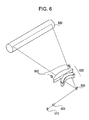
- FIG. 6 is a schematic perspective view of an image forming apparatus including an optical deflection apparatus according to the present invention.
- an optical deflector according to the present invention performs one-dimensional scanning with incident light.
- the image forming apparatus includes a laser light source 510 , a collimator lens 520 , coupled lenses 530 , and a photosensitive drum 540 .
- the collimator lens 520 and the coupled lenses 530 form an optical system.
- Laser light emitted from the laser light source 510 undergoes predetermined intensity modulation related to timing of deflection scanning with light.
- the intensity-modulated light passes through the collimator lens 520 , and the optical scanning system (optical deflector) 500 performs one-dimensional scanning with the passing light.
- the laser light used for scanning is condensed at a target position on the photosensitive drum 540 through the coupled lenses 530 to form an image.
- the photosensitive drum 540 is rotated about a rotation axis, in a direction perpendicular to the direction of scanning and is charged uniformly by a charging unit (not shown). By scanning the surface of the photosensitive drum 540 , an electrostatic latent image is formed in the scanned region. Then, a toner image is formed at an image portion of the electrostatic latent image by a developing unit (not shown). The toner image is transferred to and fixed on a sheet or the like (not shown), whereby an image is formed on the sheet.
- photodetector elements 550 are provided at positions corresponding to deflection angles of the optical deflector 500 in regions not corresponding to an effective region of the photosensitive drum 540 , and the driving method described earlier is used so that the angular velocity of the deflection angle of the optical scanner becomes substantially constant on the photosensitive drum 540 .
- printing can be performed favorably.
Landscapes
- Physics & Mathematics (AREA)
- General Physics & Mathematics (AREA)
- Optics & Photonics (AREA)
- Electromagnetism (AREA)
- Mechanical Optical Scanning Systems (AREA)
- Facsimile Scanning Arrangements (AREA)
- Laser Beam Printer (AREA)
- Facsimile Heads (AREA)
Applications Claiming Priority (2)
| Application Number | Priority Date | Filing Date | Title |
|---|---|---|---|
| JP2007-096323 | 2007-04-02 | ||
| JP2007096323A JP5064864B2 (ja) | 2007-04-02 | 2007-04-02 | 光偏向装置、画像形成装置、及び光偏向装置の駆動方法 |
Publications (2)
| Publication Number | Publication Date |
|---|---|
| US20080239445A1 US20080239445A1 (en) | 2008-10-02 |
| US7775433B2 true US7775433B2 (en) | 2010-08-17 |
Family
ID=39793819
Family Applications (1)
| Application Number | Title | Priority Date | Filing Date |
|---|---|---|---|
| US12/048,675 Expired - Fee Related US7775433B2 (en) | 2007-04-02 | 2008-03-14 | Optical deflection apparatus, image forming apparatus, and method of driving optical deflection apparatus |
Country Status (2)
| Country | Link |
|---|---|
| US (1) | US7775433B2 (ja) |
| JP (1) | JP5064864B2 (ja) |
Cited By (6)
| Publication number | Priority date | Publication date | Assignee | Title |
|---|---|---|---|---|
| US20110064470A1 (en) * | 2008-05-14 | 2011-03-17 | Canon Kabushiki Kaisha | Light deflector device and image forming apparatus |
| US20130298697A1 (en) * | 2009-07-13 | 2013-11-14 | Leroy C. Delatorre | Pressure isolated fiber optic torque sensor |
| US9310609B2 (en) | 2014-07-25 | 2016-04-12 | Hand Held Products, Inc. | Axially reinforced flexible scan element |
| US20170059852A1 (en) * | 2015-09-02 | 2017-03-02 | Robert Bosch Gmbh | Pivot apparatus for a micromirror, and illumination apparatus having a pivot apparatus for a micromirror |
| US10928620B2 (en) | 2015-12-10 | 2021-02-23 | Canon Kabushiki Kaisha | Microscope system and method of controlling the same |
| US11009693B2 (en) | 2015-12-10 | 2021-05-18 | Canon Kabushiki Kaisha | Microscope system |
Families Citing this family (13)
| Publication number | Priority date | Publication date | Assignee | Title |
|---|---|---|---|---|
| JP4289418B2 (ja) | 2007-04-26 | 2009-07-01 | ブラザー工業株式会社 | 光走査装置及び画像形成装置 |
| KR101279441B1 (ko) * | 2008-08-21 | 2013-07-05 | 삼성전자주식회사 | 멤스 미러, 미러 스캐너, 광주사 유닛 및 광주사 유닛을 채용한 화상형성장치 |
| JP5720673B2 (ja) * | 2010-03-24 | 2015-05-20 | 日本電気株式会社 | 磁気力型駆動装置、光走査装置、及び画像表示装置 |
| WO2013137882A2 (en) * | 2012-03-15 | 2013-09-19 | Optoelectronics Co., Ltd. | Scan unit for a scanning module |
| JP6104063B2 (ja) * | 2013-06-11 | 2017-03-29 | キヤノン電子株式会社 | 光走査装置、画像形成装置および映像投射装置 |
| US9798136B2 (en) | 2013-10-07 | 2017-10-24 | Intel Corporation | Method for controlling the position of a MEMS mirror |
| DE102014207891A1 (de) * | 2014-02-17 | 2015-08-20 | Robert Bosch Gmbh | Spiegelanordnung und Projektionseinrichtung |
| JP6493014B2 (ja) * | 2015-06-25 | 2019-04-03 | 株式会社デンソー | 光走査装置 |
| JP6604816B2 (ja) * | 2015-10-28 | 2019-11-13 | スタンレー電気株式会社 | 映像投射装置及びmemsミラーの制御方法 |
| US20210173198A1 (en) * | 2018-11-30 | 2021-06-10 | Pioneer Corporation | Driving device |
| US11356059B2 (en) * | 2020-04-29 | 2022-06-07 | Infineon Technologies Ag | Flexible Lissajous scanning pattern by phase modulation |
| CN111722648A (zh) * | 2020-07-02 | 2020-09-29 | 成都英飞睿技术有限公司 | 一种快速控制反射镜的控制方法、装置和系统及控制器 |
| US11493752B2 (en) * | 2021-03-05 | 2022-11-08 | Infineon Technologies Ag | Method of rectangular 2D pattern generation with lissajous scanning |
Citations (9)
| Publication number | Priority date | Publication date | Assignee | Title |
|---|---|---|---|---|
| US4859846A (en) | 1988-07-21 | 1989-08-22 | Burrer Gordon J | Dual-mode resonant scanning system |
| JPH09197334A (ja) | 1996-01-17 | 1997-07-31 | Omron Corp | 光スキャナおよびそれを用いた光センサ装置 |
| US5969465A (en) * | 1997-04-01 | 1999-10-19 | Xros, Inc. | Adjusting operating characteristics of micromachined torsional oscillators |
| US6297898B1 (en) * | 1998-09-16 | 2001-10-02 | Minolta Co., Ltd. | Optical deflection device |
| US20030063367A1 (en) * | 2001-09-11 | 2003-04-03 | Leica Microsystems Heidelberg Gmbh | Method for ascertaining position values, and scanning microscope |
| US6819103B2 (en) * | 2001-04-26 | 2004-11-16 | The Johns Hopkins University | Lorentz force driven mechanical filter/mixer designs for RF applications |
| WO2005063613A1 (en) | 2003-12-25 | 2005-07-14 | Canon Kabushiki Kaisha | Micro-oscillating member, light-deflector, and image-forming apparatus |
| JP2005292627A (ja) | 2004-04-02 | 2005-10-20 | Ricoh Co Ltd | 光走査装置 |
| US7248390B2 (en) * | 2002-03-26 | 2007-07-24 | Pentax Corporation | Light scanning device |
-
2007
- 2007-04-02 JP JP2007096323A patent/JP5064864B2/ja not_active Expired - Fee Related
-
2008
- 2008-03-14 US US12/048,675 patent/US7775433B2/en not_active Expired - Fee Related
Patent Citations (12)
| Publication number | Priority date | Publication date | Assignee | Title |
|---|---|---|---|---|
| US4859846A (en) | 1988-07-21 | 1989-08-22 | Burrer Gordon J | Dual-mode resonant scanning system |
| JPH09197334A (ja) | 1996-01-17 | 1997-07-31 | Omron Corp | 光スキャナおよびそれを用いた光センサ装置 |
| US5969465A (en) * | 1997-04-01 | 1999-10-19 | Xros, Inc. | Adjusting operating characteristics of micromachined torsional oscillators |
| US6297898B1 (en) * | 1998-09-16 | 2001-10-02 | Minolta Co., Ltd. | Optical deflection device |
| US6819103B2 (en) * | 2001-04-26 | 2004-11-16 | The Johns Hopkins University | Lorentz force driven mechanical filter/mixer designs for RF applications |
| US20030063367A1 (en) * | 2001-09-11 | 2003-04-03 | Leica Microsystems Heidelberg Gmbh | Method for ascertaining position values, and scanning microscope |
| US7248390B2 (en) * | 2002-03-26 | 2007-07-24 | Pentax Corporation | Light scanning device |
| WO2005063613A1 (en) | 2003-12-25 | 2005-07-14 | Canon Kabushiki Kaisha | Micro-oscillating member, light-deflector, and image-forming apparatus |
| JP2005208578A (ja) | 2003-12-25 | 2005-08-04 | Canon Inc | マイクロ揺動体、光偏向器、画像形成装置 |
| US20060152785A1 (en) | 2003-12-25 | 2006-07-13 | Canon Kabushiki Kaisha | Micro-oscillating member, light-deflector, and image-forming apparatus |
| US7271943B2 (en) | 2003-12-25 | 2007-09-18 | Canon Kabushiki Kaisha | Micro-oscillating member, light-deflector, and image-forming apparatus |
| JP2005292627A (ja) | 2004-04-02 | 2005-10-20 | Ricoh Co Ltd | 光走査装置 |
Cited By (9)
| Publication number | Priority date | Publication date | Assignee | Title |
|---|---|---|---|---|
| US20110064470A1 (en) * | 2008-05-14 | 2011-03-17 | Canon Kabushiki Kaisha | Light deflector device and image forming apparatus |
| US8412075B2 (en) * | 2008-05-14 | 2013-04-02 | Canon Kabushiki Kaisha | Light deflector device and image forming apparatus |
| US20130298697A1 (en) * | 2009-07-13 | 2013-11-14 | Leroy C. Delatorre | Pressure isolated fiber optic torque sensor |
| US8844363B2 (en) * | 2009-07-13 | 2014-09-30 | Leroy C. Delatorre | Pressure isolated fiber optic torque sensor |
| US9310609B2 (en) | 2014-07-25 | 2016-04-12 | Hand Held Products, Inc. | Axially reinforced flexible scan element |
| US20170059852A1 (en) * | 2015-09-02 | 2017-03-02 | Robert Bosch Gmbh | Pivot apparatus for a micromirror, and illumination apparatus having a pivot apparatus for a micromirror |
| US10914937B2 (en) * | 2015-09-02 | 2021-02-09 | Robert Bosch Gmbh | Pivot apparatus for a micromirror, and illumination apparatus having a pivot apparatus for a micromirror |
| US10928620B2 (en) | 2015-12-10 | 2021-02-23 | Canon Kabushiki Kaisha | Microscope system and method of controlling the same |
| US11009693B2 (en) | 2015-12-10 | 2021-05-18 | Canon Kabushiki Kaisha | Microscope system |
Also Published As
| Publication number | Publication date |
|---|---|
| JP5064864B2 (ja) | 2012-10-31 |
| JP2008256778A (ja) | 2008-10-23 |
| US20080239445A1 (en) | 2008-10-02 |
Similar Documents
| Publication | Publication Date | Title |
|---|---|---|
| US7775433B2 (en) | Optical deflection apparatus, image forming apparatus, and method of driving optical deflection apparatus | |
| KR100806015B1 (ko) | 마이크로요동체, 광편향기 및 화상형성장치 | |
| KR100979346B1 (ko) | 요동체 장치, 광 편향기 및 이를 제어하는 방법 | |
| US7973991B2 (en) | Oscillator device, optical deflector and driving signal generating method | |
| JP2007322466A (ja) | 光偏向器、及びそれを用いた光学機器 | |
| US20070273946A1 (en) | Optical deflector and optical apparatus using the same | |
| CN101551518B (zh) | 可移动体设备和使用该可移动体设备的光偏转器 | |
| KR20100082790A (ko) | 요동체 장치의 제조 방법, 요동체 장치를 포함한 광편향기 및 광학 기기 | |
| JP2010049155A (ja) | 光走査装置および画像形成装置 | |
| JP5065116B2 (ja) | 揺動体装置、光偏向装置、及びその制御方法 | |
| US8159734B2 (en) | Oscillator device, optical deflector and image forming apparatus using the same | |
| US20080297869A1 (en) | Oscillator device and drive control method for oscillation system of oscillator device | |
| US20110064470A1 (en) | Light deflector device and image forming apparatus | |
| US8345339B2 (en) | Optical deflector | |
| JP2009098032A (ja) | 揺動体装置、光偏向装置、及び共振周波数検知方法 | |
| US7855606B2 (en) | Oscillator device | |
| US8139279B2 (en) | Movable body apparatus, optical deflector, and optical instrument using the optical deflector | |
| JP2011180179A (ja) | 光走査装置及び画像形成装置 | |
| JP5341372B2 (ja) | 揺動体装置、揺動体装置を用いた画像形成装置 | |
| JP5408887B2 (ja) | 揺動体装置、揺動体装置を用いた画像形成装置 | |
| JP2009258392A (ja) | 揺動体装置、これを用いた光偏向装置、及び揺動体装置の駆動制御方法 | |
| JP2009042579A (ja) | 光偏向装置、及び揺動体のジッタ抑制方法 | |
| JP2009020404A (ja) | 光走査装置及び画像形成装置 | |
| JP2009025795A (ja) | 光偏向器 |
Legal Events
| Date | Code | Title | Description |
|---|---|---|---|
| AS | Assignment |
Owner name: CANON KABUSHIKI KAISHA, JAPAN Free format text: ASSIGNMENT OF ASSIGNORS INTEREST;ASSIGNOR:ANDO, HIROTAKE;REEL/FRAME:020774/0733 Effective date: 20080311 |
|
| FEPP | Fee payment procedure |
Free format text: PAYOR NUMBER ASSIGNED (ORIGINAL EVENT CODE: ASPN); ENTITY STATUS OF PATENT OWNER: LARGE ENTITY |
|
| FPAY | Fee payment |
Year of fee payment: 4 |
|
| FEPP | Fee payment procedure |
Free format text: MAINTENANCE FEE REMINDER MAILED (ORIGINAL EVENT CODE: REM.) |
|
| LAPS | Lapse for failure to pay maintenance fees |
Free format text: PATENT EXPIRED FOR FAILURE TO PAY MAINTENANCE FEES (ORIGINAL EVENT CODE: EXP.); ENTITY STATUS OF PATENT OWNER: LARGE ENTITY |
|
| STCH | Information on status: patent discontinuation |
Free format text: PATENT EXPIRED DUE TO NONPAYMENT OF MAINTENANCE FEES UNDER 37 CFR 1.362 |
|
| FP | Lapsed due to failure to pay maintenance fee |
Effective date: 20180817 |