US7758059B2 - Connector bracket of a trailer - Google Patents
Connector bracket of a trailer Download PDFInfo
- Publication number
- US7758059B2 US7758059B2 US11/662,818 US66281805A US7758059B2 US 7758059 B2 US7758059 B2 US 7758059B2 US 66281805 A US66281805 A US 66281805A US 7758059 B2 US7758059 B2 US 7758059B2
- Authority
- US
- United States
- Prior art keywords
- supply line
- trailer
- semi
- line interface
- disposed
- Prior art date
- Legal status (The legal status is an assumption and is not a legal conclusion. Google has not performed a legal analysis and makes no representation as to the accuracy of the status listed.)
- Expired - Fee Related, expires
Links
Images


Classifications
-
- B—PERFORMING OPERATIONS; TRANSPORTING
- B62—LAND VEHICLES FOR TRAVELLING OTHERWISE THAN ON RAILS
- B62D—MOTOR VEHICLES; TRAILERS
- B62D53/00—Tractor-trailer combinations; Road trains
- B62D53/04—Tractor-trailer combinations; Road trains comprising a vehicle carrying an essential part of the other vehicle's load by having supporting means for the front or rear part of the other vehicle
- B62D53/08—Fifth wheel traction couplings
-
- B—PERFORMING OPERATIONS; TRANSPORTING
- B60—VEHICLES IN GENERAL
- B60D—VEHICLE CONNECTIONS
- B60D1/00—Traction couplings; Hitches; Draw-gear; Towing devices
- B60D1/58—Auxiliary devices
- B60D1/62—Auxiliary devices involving supply lines, electric circuits, or the like
-
- B—PERFORMING OPERATIONS; TRANSPORTING
- B60—VEHICLES IN GENERAL
- B60D—VEHICLE CONNECTIONS
- B60D1/00—Traction couplings; Hitches; Draw-gear; Towing devices
- B60D1/58—Auxiliary devices
- B60D1/62—Auxiliary devices involving supply lines, electric circuits, or the like
- B60D1/64—Couplings or joints therefor
Definitions
- the invention relates to a coupling system to connect at least one supply line between a tractor vehicle and a semi-trailer, wherewith the at least one supply line has one end fixedly disposed at the tractor and has on its other end a plug or similar connector, which plug can be connected to a supply line interface associated with the semi-trailer.
- the tractor vehicle is moved below the semi-trailer and the main pivot of the semi-trailer is caused to engage with the “fifth wheel coupling” of the tractor.
- the supply lines e.g. for compressed air and electricity, and possibly pressurized hydraulic fluid, from the tractor are plugged into corresponding connectors on the semi-trailer, which receiving connectors are disposed in a supply line interface.
- a storage module is disposed on the rear side of the tractor, whereby when the tractor is running dry with no semi-trailer the plugs can be accommodated in said storage module.
- a storage module is disclosed, e.g., in U.S. Pat. No. 5,630,728.
- the connections of the supply lines to the tractor occur through the storage module or near the storage module.
- a certain amount of reserve length of the supply lines is needed, approximately the same reserve length for each such supply line, to accommodate situations when the front end of the semi-trailer swings to one side or another when negotiating curves; wherewith typically the supply lines have a spiral configuration.
- the supply line interface is disposed at the longitudinal center axis of the vehicle.
- the driver manually connects the supply lines to the supply line interface. For this, the driver must climb onto the tractor in the free space between the tractor cab and the semi-trailer, must remove the plugs from the storage module, and must plug the plugs into the supply line interface. The same procedure must be performed in reverse before the semi-trailer is separated from the tractor.
- the semi-trailer has been provided with horizontal guide rails on its front side, with a supply line interface being slidably mounted on said rails.
- a supply line interface being slidably mounted on said rails.
- said interface can be moved to the side, allowing lateral access to perform the connections.
- the supply line interface travels on the guide rails and takes a position with respect to the semi-trailer which position is shifted in the direction toward the interior of the curve.
- this solution leads to uncontrolled back and forth swinging of the supply line interface, particularly when the vehicle is negotiating curves, which mechanically stresses the supply lines themselves and may in fact damage them.
- a coupling system in which the supply line interface is movable from a “driving position”, in which position preferably said interface is held in place by catch means, into a “servicing position”.
- the supply line interface In the driving position the supply line interface is always fixedly held at a generally central location near the longitudinal axis of the vehicle, directly opposite the (also fixedly held) point of attachment of the supply lines to the tractor. This allows approximately equal lateral swinging of the supply lines to one or the other side at their connection point to the semi-trailer when the vehicle is negotiating a curve.
- This driving position corresponds to the customary position of the supply line interface according to the state of the art, viz.
- the invention eliminates the disadvantage of poor accessibility by the driver.
- the supply line interface is moved into a “servicing position”, which may be on the front side of the semi-trailer within easy reach of a driver standing next to the side of the tractor.
- the supply line interface is located in the region of the longitudinal axis of the vehicle, and in the servicing position said interface is located at one side of the semi-trailer, wherewith for safety reasons the servicing position should be located on the side of the semi-trailer which is opposite to the side on which traffic passes.
- the supply line interface is mounted on the semi-trailer by the intermediary of, or so as to be acted on by forcing and guiding means, which forcing and guiding means may have any of numerous practicable forms.
- the forcing and guiding means comprise a swing bearing which engages a swing arm which swing arm bears the supply line interface at its [distant] end.
- the supply line interface is swung between the driving position and the servicing position, in a swinging excursion around a rigid swing axis, which axis is provided by the swing bearing.
- the movement of the supply line interface may be accomplished, e.g., manually.
- the swing arm has associated with it a pull handle which the driver can grab when the supply line interface is in the driving position, said handle being, e.g., at a location easily accessible to the driver on the side of the semi-trailer.
- the pull handle In order to achieve defined swinging of the supply line interface and to avoid damaging the pull handle during operation of the handle mechanism, the pull handle should be laterally movable in a pull handle guide which is fixedly mounted on the semi-trailer.
- the pull handle is connected to the swing arm by articulation means. This enables the driver to be in a convenient position while the swinging movement is being effected, because the pull handle is “de-coupled” from the swinging movement of the swing arm.
- the swing arm and/or pulling handle may be engaged by a restoring spring which is fixedly but possibly swingably mounted to the semi-trailer.
- a restoring spring which is fixedly but possibly swingably mounted to the semi-trailer.
- a positioning cylinder may be provided for the swing arm.
- the first end of the positioning cylinder is swingably mounted on the semi-trailer, and the second end of said cylinder swingably or articulatedly engages the swing arm.
- the swing arm may be moved between the driving position and servicing position with the aid of the positioning cylinder', which may be actuated manually by the driver via valve means, or may be completely automated.
- a particularly compact solution is provided by forcing and guiding means comprising a swing drive which engages the swing arm.
- a swing drive which engages the swing arm.
- This obviates the possibly cumbersome presence of a positioning cylinder on the front wall of the semi-trailer facing the tractor; instead, the swing drive is provided in a compact coaxial disposition around the swing bearing.
- the fact that a swing drive so disposed has a low moment arm is not an important consideration, because the torque required is relatively low.
- the types of forcing and guiding means described above enable the supply line interface and/or the swing arm and/or the swing bearing to be laterally displaceable into the servicing position. This lateral displaceability allows the supply line interface to be displaced farther to reach a suitable servicing position, thereby providing for particularly convenient conditions for connection and disconnection of the supply lines.
- a swing arm is not employed but rather the forcing and guiding means comprise at least one slide rail or guide rail on which the supply line interface is slidably disposed.
- the length of the guide rail should be such that the rail extends from the region of the longitudinal center axis of the vehicle to a lateral region of the semi-trailer.
- the supply line interface and/or swing arm has at least one catch element which cooperates with at least one second catch element, which second catch element is associated with the semi-trailer.
- the first catch element may comprise, e.g., at least one pronged clip member formed on the supply line interface, which clip member at least partially surrounds a fixed second catch element when the final driving position is reached.
- the second catch element may comprise, e.g., a projecting pin element.
- a storage module may be supplied which is disposed non-centrally on the tractor, namely at a position at which the driver can readily plug in or unplug the plugs without mechanical assistance while the driver is standing next to the tractor.
- the storage module is disposed on the rear wall of the cab of the tractor.
- the storage module may be more advantageous to leave the storage module in its customarily central location and provide another holding means non-centrally on the tractor, namely a holding bracket, disposed at a position readily accessible by a person standing at the side of the tractor.
- a holding bracket disposed at a position readily accessible by a person standing at the side of the tractor.
- sensors are provided for detecting the driving position and/or the servicing position. Such sensors are particularly advantageous if the supply line interface is moved by automated means, wherewith the position and movements of said interface are displayed on a display device in the tractor cab.
- FIG. 1 is a lateral view of a tractor and semi-trailer combination
- FIG. 2 is a plan view of a tractor and semi-trailer combination, and a detail view of the storage module and supply line interface;
- FIG. 3 is a lateral view of a tractor arranged for driving without an attached trailer, and having the plug connectors of the supply lines supported on a holding bracket;
- FIG. 4 is a plan view of a tractor arranged for driving without an attached trailer, and having the plug connectors of the supply lines supported on a holding bracket;
- FIG. 5 is a front view of a semi-trailer having forcing and guiding means according to a first embodiment, and a restoring spring, in the driving position;
- FIG. 6 is a rear view of a semi-trailer having forcing and guiding means according to a first embodiment, in the servicing position;
- FIG. 7 is a front view of a semi-trailer having forcing and guiding means according to a first embodiment, and a positioning cylinder, in the driving position;
- FIG. 8 is a rear view of a semi-trailer having forcing and guiding means according to a first embodiment, and a positioning cylinder, in the servicing position;
- FIG. 9 is a view according to claim 5 , with a laterally displaceable supply line interface laterally displaceable with respect to the swing arm;
- FIG. 10 is a view according to FIG. 8 , with a laterally displaceable supply line interface laterally displaceable with respect to the swing arm;
- FIG. 11 is a rear view of a semi-trailer having forcing and guiding means according to a first embodiment, and a swing drive for accomplishing the described swinging movement;
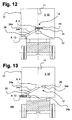
- FIG. 12 is a rear view of a semi-trailer having forcing and guiding means according to a second embodiment, in the driving position;
- FIG. 13 is a rear view of a semi-trailer having forcing and guiding means according to a second embodiment, in the servicing position.
- FIG. 1 is a schematic lateral view of a tractor vehicle 2 with a semi-trailer 3 coupled to it, in travel-ready condition.
- the semi-trailer 3 is mechanically coupled to the tractor 2 via a conventional fifth wheel coupling 30 .
- a plurality of utility supply lines 1 extend between the cab 31 of the tractor and the front wall 32 of the semi-trailer 3 only one of these, 1 , is visible in the lateral view shown in FIG. 1 .
- the supply lines 1 comprise compressed air lines and electrical lines.
- the supply lines 1 emerge from the rear of the tractor cab 31 below a storage module 7 , and are reversibly plugged into a supply line interface 8 of the semi-trailer 3 .
- the supply line interface 8 is connected to forcing and guiding means 12 which will be described in more detail in connection with FIGS. 5 to 13 .
- an auxiliary holding bracket 27 is mounted which is unused when the tractor and semi-trailer combination 2 , 3 is in the travel-ready condition with the supply lines connected to the semi-trailer.
- FIG. 2 also presents an enlarged detail view of the five supply lines 1 which exit at their first ends 4 from a position below the storage module 7 which module is fixedly mounted on the tractor cab 31 , and which bear plugs 6 on their second ends 5 .
- the plugs 6 are all plugged into the supply line interface 8 .
- the interface 8 is disposed generally along the longitudinal center axis 11 of the vehicle, at a location which will be referred to as the “driving position” 9 , used when the vehicle is ready to be driven, or is being driven. Under these circumstances, the supply line interface 8 is disposed directly opposite to the storage module 7 .
- FIGS. 3 and 4 the tractor 2 is shown without the semi-trailer 3 .
- the supply lines 1 are connected to the holding bracket 27 via their plugs 6 .
- these supply lines 1 can be easily reached by the driver standing on the side 28 of the tractor 2 . In this situation, the storage module 7 is unused.
- FIG. 5 is a front view of a semi-trailer 3 having forcing and guiding or manipulation means 12 for the supply line interface 8 according to a first embodiment.
- the supply line interface 8 is shown in the driving position 9 .
- the first embodiment illustrated comprises a swing arm 14 which is swingably mounted on the front wall 32 of the semi-trailer 3 , via a swing bearing 13 .
- the swing bearing 13 is disposed close to the longitudinal center axis 11 of the vehicle.
- the swing arm 14 In the illustrated driving position 9 of the supply line interface 8 , the swing arm 14 is disposed generally vertically upright.
- the swing arm 14 comprises three interconnected bar elements which form a right triangle.
- the supply line interface 8 is disposed at the end of the swing arm 14 , extending toward the side of the angular leg 15 of the right-triangle structure.
- the supply line interface 8 bears five plug sockets 35 , disposed symmetrically with respect to the longitudinal center axis 11 of the vehicle.
- a middle region of the swing arm 14 is engaged by a restoring spring 19 and also by a pulling handle 16 .
- the pulling handle 16 When the supply line interface 8 is in its driving position 9 , the pulling handle 16 is oriented horizontally, with the end of handle 16 which is oppositely disposed to the swing arm 14 being disposed approximately at the side 17 of the semi-trailer 3 .
- the pulling handle 16 which has its end disposed in the region of the side 17 is held, releasably, against the pulling handle guide 18 which is fixed to the front wall 32 .
- the restoring spring 19 is fixed, possibly swingably, to the semi-trailer 3 at its end oppositely disposed to the swing arm 14 , and when [the swing arm is] in the “driving position” 9 said spring is in a nearly relaxed condition.
- the swing arm 14 and the supply line interface 8 which it bears are swung sideward toward the side 17 , into the “servicing position” 10 , see FIG. 6 .
- the restoring force in the restoring spring 19 increases steadily, wherewith after the supply lines 1 are plugged in, see FIGS. 1 and 2 , the spring facilitates a defined return of the swing arm 14 from the servicing position 10 into the driving position 9 .
- any type of spring element is suitable for use as the restoring spring 19 , for the embodiment according to FIG. 5 a helical spring is suggested.
- the swing arm 14 bearing the supply line interface 8 can be held in place on the semi-trailer 3 by catch means.
- a V-shaped catch element 25 is provided on the supply line interface 8 , for this purpose; element 25 cooperates with a pin-shaped second catch element 26 mounted on the front wall 32 .
- the catch elements 25 , 26 are practicable means of preventing uncontrolled swinging of the swing arm 14 in the driving position 9 , particularly when the vehicle is negotiating curves in the road, which might cause various types of damage as well as premature wear of the swing bearing 13 .
- FIG. 6 shows the swing arm 14 in the “servicing position” 10 , in which the arm is swung laterally by 90° C.
- the pulling handle 16 is pulled in the pulling direction 36 , causing the supply line interface 8 to be moved toward the side 17 of the semi-trailer 3 , along the swing path 33 .
- the supply line interface 8 is now close to the pulling handle guide 18 , and is readily accessible by the driver standing next to the semi-trailer 3 , for plugging in the plugs 6 in FIG. 2 .
- the lower border of the swing arm 14 is disposed at the lower end of the front wall 32 of the semi-trailer 3 .
- FIGS. 7 and 8 show, in analogous views to FIGS. 5 and 6 , an alternative embodiment of the invention, with an identically configured forcing and guiding means 12 , but instead of a restoring spring 19 a positioning cylinder 20 is provided.
- the first end 21 of the positioning cylinder 20 engages the semi-trailer 3
- the second end 22 of cylinder 20 engages the swing arm 14 .
- the swing arm 14 bearing the supply line interface 8 is in the driving position 9 wherein the first catch element 25 of the supply line interface 8 partially surrounds the second catch element 26 mounted on the front wall 32 .
- the positioning cylinder 20 is fully retracted in the driving position 9 , and is oriented perpendicularly to the axial extent of the swing arm 14 and parallel to the lower side of the front wall 32 of the semi-trailer 3 .
- an actuating fluid is applied to the positioning cylinder 20 , and the cylinder 20 is moved to its extended position. This causes the supply line interface 8 with the swing arm 14 to be swung around the swing bearing 13 .
- the actuating fluid may be any suitable liquid, vapor, or gas.
- the positioning cylinder 20 In reaching the servicing position 10 , there is some swinging of the positioning cylinder 20 around i.e. at its first and second ends 21 , 22 .
- the supply line interface 8 is moved through the swing path 33 of 90° C., and in this embodiment as well the interface 8 comes to a position near the side 17 of the semi-trailer 3 .
- FIG. 9 shows an embodiment according to FIGS. 5 and 6 with a restoring spring 19 and a pulling handle 16 which engages the swing arm 14 .
- the pulling handle 16 can be pulled an additional distance in the pulling direction 36 , thereby moving the supply line interface 8 laterally out past the side 17 .
- the supply line interface 8 is caused to undergo an excursion through the swing path 33 as well as a lateral excursion 34 , into a position which particularly facilitates the plugging-in of the plugs 6 , see FIG. 2 , by the driver standing near the semi-trailer 3 .
- This additional lateral excursion 34 can also be achieved with a positioning cylinder 20 , as illustrated in FIG. 10 .
- the pulling handle 16 can be dispensed with, and the lateral excursion 34 can be brought about solely by further extension of the positioning cylinder 20 .
- FIG. 11 shows a swing arm 14 in the driving position 9 , with a swing drive means 23 disposed in the area of the swing bearing 13 , which drive 23 is capable of driving the swing arm.
- the swing drive 23 coaxially surrounds to the swing bearing 13 .
- FIGS. 12 and 13 illustrate an alternative embodiment which does not employ a swing arm 14 .
- the forcing and guiding means 12 comprise two parallel slide rails or guide rails 24 a ; 24 b which have a first end 37 , 37 on opposite sides of the longitudinal center axis of 11 of the vehicle, and have a second end 38 , 38 in the region of the side 17 of the semi-trailer 3 .
- the rails 24 a , 24 b extend in a downwardly inclined path from the center axis 11 to the side 17 .
- the supply line interface 8 is slidably guided on said rails 24 a , 24 b and can be moved between a central driving position 9 and a lateral servicing position 10 .
- FIG. 12 shows the supply line interface 8 in the driving position 9 .
- the interface 8 With the aid of the first catch element 25 disposed on the supply line interface 8 , the interface 8 is held against the second catch element 26 .
- FIG. 13 shows the supply line interface 8 in the servicing position 10 , in which a part of the interface 8 extends beyond the side 17 of the semi-trailer 3 .
Landscapes
- Engineering & Computer Science (AREA)
- Transportation (AREA)
- Mechanical Engineering (AREA)
- Chemical & Material Sciences (AREA)
- Combustion & Propulsion (AREA)
- Vehicle Cleaning, Maintenance, Repair, Refitting, And Outriggers (AREA)
- Body Structure For Vehicles (AREA)
- Details Of Connecting Devices For Male And Female Coupling (AREA)
- Vehicle Step Arrangements And Article Storage (AREA)
- Mechanical Coupling Of Light Guides (AREA)
- Connector Housings Or Holding Contact Members (AREA)
- Vehicle Body Suspensions (AREA)
- Agricultural Machines (AREA)
Applications Claiming Priority (4)
| Application Number | Priority Date | Filing Date | Title |
|---|---|---|---|
| DE102004044991.0 | 2004-09-16 | ||
| DE102004044991 | 2004-09-16 | ||
| DE102004044991A DE102004044991B4 (de) | 2004-09-16 | 2004-09-16 | Steckerkonsole |
| PCT/EP2005/009645 WO2006029753A1 (de) | 2004-09-16 | 2005-09-08 | Steckerkonsole eines aufliegers |
Publications (2)
| Publication Number | Publication Date |
|---|---|
| US20080100032A1 US20080100032A1 (en) | 2008-05-01 |
| US7758059B2 true US7758059B2 (en) | 2010-07-20 |
Family
ID=35207360
Family Applications (1)
| Application Number | Title | Priority Date | Filing Date |
|---|---|---|---|
| US11/662,818 Expired - Fee Related US7758059B2 (en) | 2004-09-16 | 2005-09-08 | Connector bracket of a trailer |
Country Status (12)
| Country | Link |
|---|---|
| US (1) | US7758059B2 (de) |
| EP (1) | EP1799470B1 (de) |
| JP (1) | JP4579986B2 (de) |
| CN (1) | CN100519238C (de) |
| AT (1) | ATE429347T1 (de) |
| AU (1) | AU2005284359B2 (de) |
| CA (1) | CA2581014C (de) |
| DE (2) | DE102004044991B4 (de) |
| ES (1) | ES2324546T3 (de) |
| PL (1) | PL1799470T3 (de) |
| RU (1) | RU2377139C2 (de) |
| WO (1) | WO2006029753A1 (de) |
Cited By (11)
| Publication number | Priority date | Publication date | Assignee | Title |
|---|---|---|---|---|
| US10029747B2 (en) | 2015-06-15 | 2018-07-24 | Saf-Holland, Inc. | Vehicle coupling lines storage and control arrangement |
| EP3623181A1 (de) * | 2018-09-14 | 2020-03-18 | SAF-Holland, Inc. | Automatische anhängerkupplungsanordnung |
| US10661622B2 (en) | 2015-06-15 | 2020-05-26 | Saf-Holland, Inc. | Vehicle coupling lines storage and control arrangement |
| US10670479B2 (en) | 2018-02-27 | 2020-06-02 | Methode Electronics, Inc. | Towing systems and methods using magnetic field sensing |
| US10696109B2 (en) | 2017-03-22 | 2020-06-30 | Methode Electronics Malta Ltd. | Magnetolastic based sensor assembly |
| US11014417B2 (en) | 2018-02-27 | 2021-05-25 | Methode Electronics, Inc. | Towing systems and methods using magnetic field sensing |
| US11084342B2 (en) | 2018-02-27 | 2021-08-10 | Methode Electronics, Inc. | Towing systems and methods using magnetic field sensing |
| US11135882B2 (en) | 2018-02-27 | 2021-10-05 | Methode Electronics, Inc. | Towing systems and methods using magnetic field sensing |
| US11221262B2 (en) | 2018-02-27 | 2022-01-11 | Methode Electronics, Inc. | Towing systems and methods using magnetic field sensing |
| US11363438B2 (en) * | 2018-05-25 | 2022-06-14 | Paccar Inc. | Near field connection for secure tractor trailer communication, and associated systems and methods |
| US11491832B2 (en) | 2018-02-27 | 2022-11-08 | Methode Electronics, Inc. | Towing systems and methods using magnetic field sensing |
Families Citing this family (15)
| Publication number | Priority date | Publication date | Assignee | Title |
|---|---|---|---|---|
| DE102006012800B4 (de) * | 2006-03-15 | 2008-06-05 | Jost-Werke Gmbh | Steckerkonsole |
| GB2467955B (en) * | 2009-02-23 | 2014-02-19 | Don Bur Bodies & Trailers Ltd | Improvements in or relating to trailers or containers |
| EP2417007B1 (de) * | 2009-04-10 | 2015-01-28 | SAF-Holland, Inc. | Automatisches pneumatisch-elektrisches kopplersystem für traktor/anhänger-kombinationsfahrzeuge |
| JP5403749B2 (ja) * | 2009-12-16 | 2014-01-29 | Udトラックス株式会社 | コイル状線条部材の保持装置 |
| DE102011014271A1 (de) * | 2011-03-17 | 2012-09-20 | Knorr-Bremse Systeme für Nutzfahrzeuge GmbH | Kupplungskopf-Anordnung für eine pneumatische und elektrische Verbindung eines Anhängers an ein Zugfahrzeug |
| JP6061522B2 (ja) * | 2012-07-02 | 2017-01-18 | 東プレ株式会社 | コンテナ着脱式冷凍車 |
| GB2507802B (en) * | 2012-11-12 | 2017-06-14 | Don-Bur (Bodies & Trailers) Ltd | Improvements in or relating to trailers or containers |
| GB201615857D0 (en) * | 2016-09-16 | 2016-11-02 | Bennion Commercial Repairs Ltd | Pivotable trailer coupling |
| JP6188904B2 (ja) * | 2016-10-28 | 2017-08-30 | 東プレ株式会社 | コンテナ着脱式冷凍車 |
| US10202063B1 (en) * | 2017-09-28 | 2019-02-12 | Road Gear Truck Equipment, LLC | Support bracket for a tractor-trailer semi-truck cab rack |
| DE102018117584A1 (de) * | 2018-07-20 | 2020-01-23 | Jost-Werke Deutschland Gmbh | Steckkupplungssystem sowie kupplungssystem |
| DE102019000635A1 (de) | 2019-01-29 | 2019-06-06 | Daimler Ag | Vorrichtung und Verfahren zur Vorbereitung eines Fahrzeuganhängers auf einen Fahrbetrieb |
| DE102019202352A1 (de) * | 2019-02-21 | 2020-08-27 | Jost-Werke Deutschland Gmbh | Verbindungseinrichtung, Verbindungssystem sowie Sattelzug |
| US11560188B2 (en) * | 2019-07-12 | 2023-01-24 | Isee, Inc. | Automatic tractor trailer coupling |
| GB201910606D0 (en) * | 2019-07-24 | 2019-09-04 | Fluid Power Design Ltd | Equitment for services interconnections of tractor-trailer combinations |
Citations (17)
| Publication number | Priority date | Publication date | Assignee | Title |
|---|---|---|---|---|
| US4092034A (en) * | 1976-11-03 | 1978-05-30 | Robert Becker | Unitized power outlet housing for truck tractor body |
| US4772220A (en) * | 1987-11-12 | 1988-09-20 | Hallier Jr Martin J | Clip/bracket for trailer wiring connector |
| US5082217A (en) * | 1991-03-27 | 1992-01-21 | Deere & Company | Hydraulic hose support for an implement |
| US5184960A (en) * | 1992-04-06 | 1993-02-09 | Hopkins Manufacturing Corporation | Trailer light connection system |
| DE4135795A1 (de) | 1991-10-30 | 1993-05-06 | Rockinger Spezialfabrik Fuer Anhaengerkupplungen Gmbh & Co, 8000 Muenchen, De | Sattelzug stichwort: multikupplung fuer sattelauflieger |
| US5516136A (en) * | 1994-08-03 | 1996-05-14 | Matthews; Peter L. | Apparatus for the coupling of lines between a tractor and a trailer |
| US5630728A (en) | 1995-11-01 | 1997-05-20 | Watters, Jr.; Henry W. | Plug holder |
| US5660408A (en) | 1995-07-12 | 1997-08-26 | Paccar Inc | Gladhand and electrical connector holder |
| US5693985A (en) * | 1995-08-31 | 1997-12-02 | Eaton Corporation | Programmable trailer indentification system integrated into a truck tractor and trailer communication system |
| US5739592A (en) * | 1996-01-31 | 1998-04-14 | Grote Industries, Inc. | Power and communications link between a tractor and trailer |
| EP0853033A2 (de) | 1997-01-09 | 1998-07-15 | Montracon (Refrigerated Vehicles) Ltd. | Anhänger |
| US5957475A (en) * | 1998-06-19 | 1999-09-28 | Pearen; Donald C. | Offset hitch for use in towing an implement |
| EP0983932A2 (de) | 1998-09-02 | 2000-03-08 | ROCKINGER Spezialfabrik für Anhängerkupplungen GmbH & Co. | Schleppzug |
| EP1040988A2 (de) | 1999-04-01 | 2000-10-04 | Montracon (Refrigerated Vehicles) Ltd. | Anhänger mit Anordnung für Leitungen/Rohrleitungen |
| GB2365397A (en) | 2000-06-30 | 2002-02-20 | Safeway Stores | Trailer mounting for service lines |
| US6651940B2 (en) * | 2001-08-08 | 2003-11-25 | Gene R. Hill, Sr. | Tractor-trailer support apparatus |
| US20040164516A1 (en) | 2003-02-24 | 2004-08-26 | Volvo Trucks North America, Inc. | Trailer line routing |
Family Cites Families (1)
| Publication number | Priority date | Publication date | Assignee | Title |
|---|---|---|---|---|
| US5346239A (en) * | 1991-10-30 | 1994-09-13 | Rockinger Spezialfabrik Fur Anhangerkupplungen Gmbh & Co. | Tractor train, optionally an articulated train |
-
2004
- 2004-09-16 DE DE102004044991A patent/DE102004044991B4/de not_active Expired - Fee Related
-
2005
- 2005-09-08 DE DE502005007155T patent/DE502005007155D1/de active Active
- 2005-09-08 AU AU2005284359A patent/AU2005284359B2/en not_active Ceased
- 2005-09-08 AT AT05784602T patent/ATE429347T1/de active
- 2005-09-08 CA CA2581014A patent/CA2581014C/en not_active Expired - Fee Related
- 2005-09-08 WO PCT/EP2005/009645 patent/WO2006029753A1/de active Application Filing
- 2005-09-08 ES ES05784602T patent/ES2324546T3/es active Active
- 2005-09-08 PL PL05784602T patent/PL1799470T3/pl unknown
- 2005-09-08 JP JP2007531643A patent/JP4579986B2/ja not_active Expired - Fee Related
- 2005-09-08 RU RU2007114034/11A patent/RU2377139C2/ru not_active IP Right Cessation
- 2005-09-08 US US11/662,818 patent/US7758059B2/en not_active Expired - Fee Related
- 2005-09-08 EP EP05784602A patent/EP1799470B1/de not_active Not-in-force
- 2005-09-08 CN CNB2005800312604A patent/CN100519238C/zh not_active Expired - Fee Related
Patent Citations (19)
| Publication number | Priority date | Publication date | Assignee | Title |
|---|---|---|---|---|
| US4092034A (en) * | 1976-11-03 | 1978-05-30 | Robert Becker | Unitized power outlet housing for truck tractor body |
| US4772220A (en) * | 1987-11-12 | 1988-09-20 | Hallier Jr Martin J | Clip/bracket for trailer wiring connector |
| US5082217A (en) * | 1991-03-27 | 1992-01-21 | Deere & Company | Hydraulic hose support for an implement |
| DE4135795A1 (de) | 1991-10-30 | 1993-05-06 | Rockinger Spezialfabrik Fuer Anhaengerkupplungen Gmbh & Co, 8000 Muenchen, De | Sattelzug stichwort: multikupplung fuer sattelauflieger |
| US5184960A (en) * | 1992-04-06 | 1993-02-09 | Hopkins Manufacturing Corporation | Trailer light connection system |
| US5516136A (en) * | 1994-08-03 | 1996-05-14 | Matthews; Peter L. | Apparatus for the coupling of lines between a tractor and a trailer |
| US5660408A (en) | 1995-07-12 | 1997-08-26 | Paccar Inc | Gladhand and electrical connector holder |
| US5693985A (en) * | 1995-08-31 | 1997-12-02 | Eaton Corporation | Programmable trailer indentification system integrated into a truck tractor and trailer communication system |
| US5630728A (en) | 1995-11-01 | 1997-05-20 | Watters, Jr.; Henry W. | Plug holder |
| US5739592A (en) * | 1996-01-31 | 1998-04-14 | Grote Industries, Inc. | Power and communications link between a tractor and trailer |
| EP0853033A2 (de) | 1997-01-09 | 1998-07-15 | Montracon (Refrigerated Vehicles) Ltd. | Anhänger |
| US5957475A (en) * | 1998-06-19 | 1999-09-28 | Pearen; Donald C. | Offset hitch for use in towing an implement |
| EP0983932A2 (de) | 1998-09-02 | 2000-03-08 | ROCKINGER Spezialfabrik für Anhängerkupplungen GmbH & Co. | Schleppzug |
| DE19840007A1 (de) | 1998-09-02 | 2000-03-09 | Rockinger Spezial Fab Joh | Schleppzug |
| EP1040988A2 (de) | 1999-04-01 | 2000-10-04 | Montracon (Refrigerated Vehicles) Ltd. | Anhänger mit Anordnung für Leitungen/Rohrleitungen |
| GB2365397A (en) | 2000-06-30 | 2002-02-20 | Safeway Stores | Trailer mounting for service lines |
| US6651940B2 (en) * | 2001-08-08 | 2003-11-25 | Gene R. Hill, Sr. | Tractor-trailer support apparatus |
| US20040164516A1 (en) | 2003-02-24 | 2004-08-26 | Volvo Trucks North America, Inc. | Trailer line routing |
| US6902180B2 (en) * | 2003-02-24 | 2005-06-07 | Volvo Trucks North America, Inc. | Trailer line routing |
Cited By (17)
| Publication number | Priority date | Publication date | Assignee | Title |
|---|---|---|---|---|
| US10421325B2 (en) | 2015-06-15 | 2019-09-24 | Saf-Holland, Inc. | Vehicle coupling lines storage and control arrangement |
| US11376907B2 (en) | 2015-06-15 | 2022-07-05 | Saf-Holland, Inc. | Vehicle coupling lines storage and control arrangement |
| US10661622B2 (en) | 2015-06-15 | 2020-05-26 | Saf-Holland, Inc. | Vehicle coupling lines storage and control arrangement |
| US10029747B2 (en) | 2015-06-15 | 2018-07-24 | Saf-Holland, Inc. | Vehicle coupling lines storage and control arrangement |
| US10850782B2 (en) | 2015-06-15 | 2020-12-01 | Saf-Holland, Inc. | Vehicle coupling lines storage and control arrangement |
| US10940726B2 (en) | 2017-03-22 | 2021-03-09 | Methode Electronics Malta Ltd. | Magnetoelastic based sensor assembly |
| US10696109B2 (en) | 2017-03-22 | 2020-06-30 | Methode Electronics Malta Ltd. | Magnetolastic based sensor assembly |
| US11014417B2 (en) | 2018-02-27 | 2021-05-25 | Methode Electronics, Inc. | Towing systems and methods using magnetic field sensing |
| US10670479B2 (en) | 2018-02-27 | 2020-06-02 | Methode Electronics, Inc. | Towing systems and methods using magnetic field sensing |
| US11084342B2 (en) | 2018-02-27 | 2021-08-10 | Methode Electronics, Inc. | Towing systems and methods using magnetic field sensing |
| US11135882B2 (en) | 2018-02-27 | 2021-10-05 | Methode Electronics, Inc. | Towing systems and methods using magnetic field sensing |
| US11221262B2 (en) | 2018-02-27 | 2022-01-11 | Methode Electronics, Inc. | Towing systems and methods using magnetic field sensing |
| US11491832B2 (en) | 2018-02-27 | 2022-11-08 | Methode Electronics, Inc. | Towing systems and methods using magnetic field sensing |
| US11363438B2 (en) * | 2018-05-25 | 2022-06-14 | Paccar Inc. | Near field connection for secure tractor trailer communication, and associated systems and methods |
| EP3623181A1 (de) * | 2018-09-14 | 2020-03-18 | SAF-Holland, Inc. | Automatische anhängerkupplungsanordnung |
| US11618289B2 (en) | 2018-09-14 | 2023-04-04 | Saf-Holland, Inc. | Automated trailer coupling arrangement |
| US11981171B2 (en) | 2018-09-14 | 2024-05-14 | Saf-Holland, Inc. | Automated trailer coupling arrangement |
Also Published As
| Publication number | Publication date |
|---|---|
| JP4579986B2 (ja) | 2010-11-10 |
| ES2324546T3 (es) | 2009-08-10 |
| EP1799470A1 (de) | 2007-06-27 |
| EP1799470B1 (de) | 2009-04-22 |
| CA2581014A1 (en) | 2006-03-23 |
| DE502005007155D1 (de) | 2009-06-04 |
| JP2008513267A (ja) | 2008-05-01 |
| US20080100032A1 (en) | 2008-05-01 |
| AU2005284359B2 (en) | 2012-03-29 |
| ATE429347T1 (de) | 2009-05-15 |
| CN101022966A (zh) | 2007-08-22 |
| RU2007114034A (ru) | 2008-10-27 |
| PL1799470T3 (pl) | 2009-09-30 |
| DE102004044991A1 (de) | 2006-04-06 |
| AU2005284359A1 (en) | 2006-03-23 |
| CA2581014C (en) | 2013-07-02 |
| WO2006029753A1 (de) | 2006-03-23 |
| RU2377139C2 (ru) | 2009-12-27 |
| CN100519238C (zh) | 2009-07-29 |
| DE102004044991B4 (de) | 2009-02-12 |
Similar Documents
| Publication | Publication Date | Title |
|---|---|---|
| US7758059B2 (en) | Connector bracket of a trailer | |
| US7854443B2 (en) | System for connecting supply lines | |
| US7967319B2 (en) | Vehicle coupling aid with automatically moving supply line connector bracket | |
| JP5290373B2 (ja) | 差込接続 | |
| US8505949B2 (en) | Automatic pneumatic/electrical coupler system for tractor-trailer combination vehicles | |
| AU2009224649B2 (en) | Method and system for recognising the state of connection of connectors | |
| US3964767A (en) | Anti-sway trailer hitch | |
| BRPI0711085A2 (pt) | sistema de acoplamento para a conexão de cabos de suprimento | |
| BRPI0903305A2 (pt) | console de conector para veìculo reboque de um caminhão com reboque | |
| CN112429119B (zh) | 同轨迹牵引拖车 | |
| AU2006201248A1 (en) | Device for automated coupling | |
| US3099462A (en) | Vehicle coupler or hitch | |
| US20080179860A1 (en) | Automatic Tow Switch | |
| US7344344B2 (en) | System and method for loading or maneuvering a boat onto a boat trailer | |
| EP1456043B1 (de) | Stützbeinanordnung für fahrzeuganhänger | |
| US6698783B1 (en) | Trailer hitch guide | |
| US20020145268A1 (en) | Trailer hitch guide | |
| JP3305214B2 (ja) | 車両連結用カプラからキングピンを解放する装置 | |
| AU2018241166B2 (en) | Safety apparatus for a fifth wheel coupling | |
| US2574276A (en) | Trailer hitch | |
| KR20240046250A (ko) | 케이블 라우팅 장치 |
Legal Events
| Date | Code | Title | Description |
|---|---|---|---|
| AS | Assignment |
Owner name: JOST-WERKE GMBH & CO., KG, GERMANY Free format text: ASSIGNMENT OF ASSIGNORS INTEREST;ASSIGNORS:GALLEGO, JOSE MANUEL ALGUERA;RICHTER, ERNST MARTIN;REEL/FRAME:019080/0865;SIGNING DATES FROM 20070305 TO 20070306 Owner name: JOST-WERKE GMBH & CO., KG, GERMANY Free format text: ASSIGNMENT OF ASSIGNORS INTEREST;ASSIGNORS:GALLEGO, JOSE MANUEL ALGUERA;RICHTER, ERNST MARTIN;SIGNING DATES FROM 20070305 TO 20070306;REEL/FRAME:019080/0865 |
|
| AS | Assignment |
Owner name: JOST-WERKE GMBH, GERMANY Free format text: CHANGE OF NAME;ASSIGNOR:JOST-WERKE GMBH & CO. KG;REEL/FRAME:020442/0547 Effective date: 20071116 Owner name: JOST-WERKE GMBH,GERMANY Free format text: CHANGE OF NAME;ASSIGNOR:JOST-WERKE GMBH & CO. KG;REEL/FRAME:020442/0547 Effective date: 20071116 |
|
| FPAY | Fee payment |
Year of fee payment: 4 |
|
| FEPP | Fee payment procedure |
Free format text: MAINTENANCE FEE REMINDER MAILED (ORIGINAL EVENT CODE: REM.) |
|
| LAPS | Lapse for failure to pay maintenance fees |
Free format text: PATENT EXPIRED FOR FAILURE TO PAY MAINTENANCE FEES (ORIGINAL EVENT CODE: EXP.); ENTITY STATUS OF PATENT OWNER: LARGE ENTITY |
|
| STCH | Information on status: patent discontinuation |
Free format text: PATENT EXPIRED DUE TO NONPAYMENT OF MAINTENANCE FEES UNDER 37 CFR 1.362 |
|
| FP | Lapsed due to failure to pay maintenance fee |
Effective date: 20180720 |