US7743909B2 - Conveying installation for transporting goods by way of a conveyor belt - Google Patents
Conveying installation for transporting goods by way of a conveyor belt Download PDFInfo
- Publication number
- US7743909B2 US7743909B2 US11/958,997 US95899707A US7743909B2 US 7743909 B2 US7743909 B2 US 7743909B2 US 95899707 A US95899707 A US 95899707A US 7743909 B2 US7743909 B2 US 7743909B2
- Authority
- US
- United States
- Prior art keywords
- conveyor belt
- supporting
- scraper strip
- conveying installation
- control assembly
- Prior art date
- Legal status (The legal status is an assumption and is not a legal conclusion. Google has not performed a legal analysis and makes no representation as to the accuracy of the status listed.)
- Expired - Fee Related, expires
Links
Images


Classifications
-
- B—PERFORMING OPERATIONS; TRANSPORTING
- B65—CONVEYING; PACKING; STORING; HANDLING THIN OR FILAMENTARY MATERIAL
- B65G—TRANSPORT OR STORAGE DEVICES, e.g. CONVEYORS FOR LOADING OR TIPPING, SHOP CONVEYOR SYSTEMS OR PNEUMATIC TUBE CONVEYORS
- B65G39/00—Rollers, e.g. drive rollers, or arrangements thereof incorporated in roller-ways or other types of mechanical conveyors
- B65G39/10—Arrangements of rollers
- B65G39/20—Arrangements of rollers attached to moving belts or chains
-
- B—PERFORMING OPERATIONS; TRANSPORTING
- B65—CONVEYING; PACKING; STORING; HANDLING THIN OR FILAMENTARY MATERIAL
- B65G—TRANSPORT OR STORAGE DEVICES, e.g. CONVEYORS FOR LOADING OR TIPPING, SHOP CONVEYOR SYSTEMS OR PNEUMATIC TUBE CONVEYORS
- B65G17/00—Conveyors having an endless traction element, e.g. a chain, transmitting movement to a continuous or substantially-continuous load-carrying surface or to a series of individual load-carriers; Endless-chain conveyors in which the chains form the load-carrying surface
- B65G17/30—Details; Auxiliary devices
-
- B—PERFORMING OPERATIONS; TRANSPORTING
- B65—CONVEYING; PACKING; STORING; HANDLING THIN OR FILAMENTARY MATERIAL
- B65G—TRANSPORT OR STORAGE DEVICES, e.g. CONVEYORS FOR LOADING OR TIPPING, SHOP CONVEYOR SYSTEMS OR PNEUMATIC TUBE CONVEYORS
- B65G21/00—Supporting or protective framework or housings for endless load-carriers or traction elements of belt or chain conveyors
- B65G21/02—Supporting or protective framework or housings for endless load-carriers or traction elements of belt or chain conveyors consisting essentially of struts, ties, or like structural elements
- B65G21/04—Supporting or protective framework or housings for endless load-carriers or traction elements of belt or chain conveyors consisting essentially of struts, ties, or like structural elements the ties being formed by longitudinal cables or ropes
-
- B—PERFORMING OPERATIONS; TRANSPORTING
- B65—CONVEYING; PACKING; STORING; HANDLING THIN OR FILAMENTARY MATERIAL
- B65G—TRANSPORT OR STORAGE DEVICES, e.g. CONVEYORS FOR LOADING OR TIPPING, SHOP CONVEYOR SYSTEMS OR PNEUMATIC TUBE CONVEYORS
- B65G21/00—Supporting or protective framework or housings for endless load-carriers or traction elements of belt or chain conveyors
- B65G21/20—Means incorporated in, or attached to, framework or housings for guiding load-carriers, traction elements or loads supported on moving surfaces
- B65G21/22—Rails or the like engaging sliding elements or rollers attached to load-carriers or traction elements
-
- B—PERFORMING OPERATIONS; TRANSPORTING
- B65—CONVEYING; PACKING; STORING; HANDLING THIN OR FILAMENTARY MATERIAL
- B65G—TRANSPORT OR STORAGE DEVICES, e.g. CONVEYORS FOR LOADING OR TIPPING, SHOP CONVEYOR SYSTEMS OR PNEUMATIC TUBE CONVEYORS
- B65G23/00—Driving gear for endless conveyors; Belt- or chain-tensioning arrangements
- B65G23/02—Belt- or chain-engaging elements
- B65G23/04—Drums, rollers, or wheels
- B65G23/08—Drums, rollers, or wheels with self-contained driving mechanisms, e.g. motors and associated gearing
-
- B—PERFORMING OPERATIONS; TRANSPORTING
- B65—CONVEYING; PACKING; STORING; HANDLING THIN OR FILAMENTARY MATERIAL
- B65G—TRANSPORT OR STORAGE DEVICES, e.g. CONVEYORS FOR LOADING OR TIPPING, SHOP CONVEYOR SYSTEMS OR PNEUMATIC TUBE CONVEYORS
- B65G45/00—Lubricating, cleaning, or clearing devices
- B65G45/10—Cleaning devices
- B65G45/12—Cleaning devices comprising scrapers
- B65G45/16—Cleaning devices comprising scrapers with scraper biasing means
Definitions
- the present invention relates to a conveying installation for transporting goods, having a conveyor belt which is guided over deflecting drums in a loading station and in an unloading station of the installation and which is fastened on the underside of supporting bars which are oriented transversely to the movement direction of the conveyor belt and are spaced apart from one another in the movement direction of the conveyor belt.
- Supporting rollers are mounted in each case at the two lateral ends of the supporting bars, and these supporting rollers roll on two pairs of supporting cables or supporting rails which are provided along the installation and are respectively assigned to the forward strand and the return strand of the conveyor belt.
- Such a conveying installation which is described for example from U.S. Pat. No. 6,588,583 B2, can be used to convey, using conveyor belts designed with undulating edges, articles such as teardown materials, ore-bearing minerals, coal and the like from the region in which they occur or are extracted, beyond obstacles such as valleys, into another region in which they are stored or processed, or from which they are transported away by way of motor vehicles. Since the conveyor belt of such a conveying installation is guided along supporting cables, the relevant articles can be conveyed a long distance from a loading station to an unloading station with comparatively low technical outlay.
- a conveying installation for transporting goods comprising:
- a conveyor belt extending between a loading station and an unloading station in a forward strand and a return strand and being guided about deflecting drums in the loading and unloading stations;
- said supporting bars having lateral ends and supporting rollers mounted to said lateral ends and disposed for rolling on said supporting cables or supporting rails;
- a configuration for cleaning said conveyor belt including a scraper strip movably disposed in a direction to said conveyor belt and a control assembly for moving said scraper strip towards said conveyor belt;
- control assembly being controlled by a position of said supporting bars, wherein said scraper strip is brought substantially into abutment against said conveyor belt between said supporting bars, whereas said scraper strip is lifted off from said conveyor belt in a region of a respective said supporting bar.
- the assembly for cleaning the conveyor belt includes a scraper strip or the like which can be moved in the direction of the conveyor belt by way of a control assembly, the control assembly being controlled by the position of the supporting bars such that the scraper strip or the like is brought at least more or less into abutment against the conveyor belt between the supporting bars, whereas it is raised off from the conveyor belt in the region of a supporting bar.
- the scraper strip is preferably fastened on a shaft which can be pivoted in relation to the conveyor belt by means of a servomotor. Also preferably provided is a restoring spring, by means of which the scraper strip can be raised off in particular when the servomotor fails. Furthermore, preferably the deflecting drum located in the unloading station is assigned at least one proximity switch which can sense the position of a supporting bar moving in the direction of the scraper strip and can control the servomotor. Furthermore, preferably the control assembly is designed with at least one interrupting rod, which switches off the drive for the conveying installation when the control assembly malfunctions.
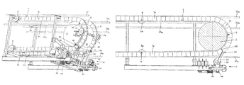
- FIG. 1 shows an axonometric illustration of a conveying installation according to the invention in the region of the unloading station;
- FIG. 2 is a side view of a first operating positions of the conveying installation according to the invention in the region of the unloading station;
- FIG. 2A is a similar view of a second operating position
- FIG. 2B is a similar view of a third operating position.
- the conveying installation has a conveyor belt 1 which is guided over deflecting drums in the loading station and in the unloading station (i.e., the terminal stations). At least one of these deflecting drums is a driven pulley.
- the conveyor belt 1 which has a more or less rectangular conveying region in cross section, is designed laterally with undulating edges 11 , as a result of which it can be guided, in the loading station and in the unloading station, over the deflecting drums located in these stations. In the unloading station, the conveyor belt is guided over the deflecting drum 2 .
- the conveying installation also has three pairs of cables 31 and 31 a , 32 and 32 a and 33 and 33 a , which are connected to one another along the entire extent of the installation by means of spaced-apart supporting frames, as a result of which these cables are spaced apart from one another by the necessary distances throughout the installation.
- the two top cables 31 and 31 a here serve as supporting cables of the conveying installation, and these absorb the loading which occurs in the conveying installation.
- the two central cables 32 and 32 a serve as guide cables for the strand 1 a of the conveyor belt 1 , this strand moving from the loading station to the unloading station
- the two bottom cables 33 and 33 a serve as guide cables for the strand 1 b of the conveyor belt 1 , this strand moving back from the unloading station to the loading station.
- the conveyor belt 1 is also provided with supporting bars 4 , which have the conveyor belt 1 fastened on their undersides (here, defined with reference to the forward strand, where the conveyor belt carries the goods) and are spaced apart from one another by distances of, for example, 5 m to 8 m.
- These supporting bars 4 subdivide the conveyor belt 1 into trough-like regions, and this makes it possible for the conveyor belt to be guided even over inclined sections of the conveying path without the articles located on the conveyor belt sliding off as a result.
- Supporting rollers 5 and 5 a are mounted at the two ends of the respective supporting bars 4 , in which case the supporting rollers 5 and 5 a of the strand 1 a of the conveyor belt 1 , this strand moving from the loading station to the unloading station, roll along the guide cables 32 and 32 a and the supporting rollers 5 and 5 a of the strand 1 b of the conveyor belt 1 , this strand moving back to the loading station, roll along the guide cables 33 and 33 a.
- the supporting rollers 5 and 5 a are guided along guide rails 34 and 34 a .
- Such guide rails are also provided in the loading station.
- the conveyor belt 1 is assigned a scraper arrangement 6 by means of which, once the conveyor belt 1 has been unloaded, any article fractions remaining on the conveyor belt are removed.
- the scraper arrangement 6 has a shaft 61 which is designed with radially projecting supporting arms 62 , on which a scraper strip 63 or the like is fastened.
- the shaft 61 is additionally designed with radially projecting regulating arms 64 which are subject to the action of restoring springs 65 , which cause the shaft 61 to rotate in the clockwise direction, as a result of which the scraper strip 63 is pivoted away from the conveyor belt 1 .
- the shaft 61 is assigned a servomotor 66 , by means of which it is rotated such that the scraper strip 63 is pivoted in the direction of the conveyor belt 1 , counter to the action of the restoring springs 65 , and is also pivoted away from the conveyor belt 1 .
- the scraper strip 63 is only raised off from the conveyor belt 1 by the restoring springs 65 .
- the servomotor 66 is controlled by proximity switches 67 , which each sense a supporting bar 4 located in the region of the same.
- the output signals of the proximity switches 67 are transmitted to a control unit for the servomotor 66 .
- This scraper configuration 6 operates as follows:
- the servomotor 66 pivots the scraper strip 63 , counter to the action of the restoring springs 65 , onto the loading surface 10 of the conveyor belt 1 , the scraper strip being located between the two undulating edges 11 . As a result, any articles remaining on the conveyor belt 1 are removed from the same. As soon as the scraper strip 63 approaches a supporting bar 4 , it is pivoted away from the conveyor belt 1 by the servomotor 66 . If functioning of the servomotor 66 ceases, the scraper strip 63 is pivoted away from the conveyor belt 1 by the restoring spring 65 .
- FIGS. 2 , 2 A, and 2 B illustrate three different operating positions of the scraper strip 63 , as follows:
Landscapes
- Engineering & Computer Science (AREA)
- Mechanical Engineering (AREA)
- Structure Of Belt Conveyors (AREA)
- Branching, Merging, And Special Transfer Between Conveyors (AREA)
- Intermediate Stations On Conveyors (AREA)
Applications Claiming Priority (2)
| Application Number | Priority Date | Filing Date | Title |
|---|---|---|---|
| AT0170307A AT505925B1 (de) | 2007-10-22 | 2007-10-22 | Förderanlage zum transport von gütern mit einem förderband |
| ATA1703/2007 | 2007-10-22 |
Publications (2)
| Publication Number | Publication Date |
|---|---|
| US20090101473A1 US20090101473A1 (en) | 2009-04-23 |
| US7743909B2 true US7743909B2 (en) | 2010-06-29 |
Family
ID=40344396
Family Applications (1)
| Application Number | Title | Priority Date | Filing Date |
|---|---|---|---|
| US11/958,997 Expired - Fee Related US7743909B2 (en) | 2007-10-22 | 2007-12-18 | Conveying installation for transporting goods by way of a conveyor belt |
Country Status (15)
| Country | Link |
|---|---|
| US (1) | US7743909B2 (pt) |
| EP (1) | EP2052995B1 (pt) |
| JP (1) | JP2009102163A (pt) |
| KR (1) | KR20090040824A (pt) |
| CN (1) | CN101417735A (pt) |
| AT (2) | AT505925B1 (pt) |
| AU (1) | AU2007254685A1 (pt) |
| BR (1) | BRPI0705001A2 (pt) |
| CA (1) | CA2615201A1 (pt) |
| DE (1) | DE502007002363D1 (pt) |
| ES (1) | ES2337518T3 (pt) |
| PL (1) | PL2052995T3 (pt) |
| PT (1) | PT2052995E (pt) |
| RU (1) | RU2007149267A (pt) |
| ZA (1) | ZA200710963B (pt) |
Cited By (3)
| Publication number | Priority date | Publication date | Assignee | Title |
|---|---|---|---|---|
| US20090173599A1 (en) * | 2008-01-03 | 2009-07-09 | Iet Combustion Llc | System and Method for Product Removal |
| US9253945B2 (en) * | 2012-09-14 | 2016-02-09 | Cnh Industrial America Llc | Self-adjusting object deflector for an agricultural harvester feeder |
| US10280010B2 (en) * | 2017-08-24 | 2019-05-07 | Precision, Inc. | Scraper assemblies for removing carryover material from a conveyor belt or roller |
Families Citing this family (14)
| Publication number | Priority date | Publication date | Assignee | Title |
|---|---|---|---|---|
| DE202009001482U1 (de) | 2009-02-06 | 2010-06-02 | F.E. Schulte Strathaus GmbH & Co. KG Fördertechnik Dichtungssysteme | Vorrichtung zum Reinigen der Oberfläche eines Förderbandes mit Wellkanten |
| ES2406329T3 (es) * | 2010-12-02 | 2013-06-06 | Innova Patent Gmbh | Instalación de transporte para el transporte de productos a granel |
| KR101280706B1 (ko) * | 2013-03-28 | 2013-07-01 | 김덕남 | 침대 매트리스의 스프링구조체 제조용 스프링 공급장치 |
| CN103231892B (zh) * | 2013-05-07 | 2015-05-06 | 桂林电子科技大学 | 双边驱动式环形导轨芯片传输装置 |
| AT516277B1 (de) * | 2014-08-13 | 2016-04-15 | Innova Patent Gmbh | Förderanlage zum Transport von Gütern |
| DE102015104932B3 (de) * | 2015-03-31 | 2016-06-02 | Heraeus Noblelight Gmbh | Vorrichtung zur Wärmebehandlung |
| CN105416993B (zh) * | 2015-12-03 | 2017-09-26 | 力博重工科技股份有限公司 | 轨道式带式输送机 |
| CN111137655A (zh) * | 2019-12-20 | 2020-05-12 | 大唐甘肃发电有限公司景泰发电厂 | 一种热电厂锅炉炉渣的降尘输送结构 |
| CN113071884B (zh) * | 2021-03-26 | 2022-09-13 | 云南滇东雨汪能源有限公司 | 一种煤矿皮带机机尾刮煤装置 |
| CN113911627B (zh) * | 2021-08-30 | 2023-09-01 | 华能秦煤瑞金发电有限责任公司 | 一种基于高效的称重给煤机 |
| CN113602765B (zh) * | 2021-10-11 | 2021-12-14 | 江苏德博利恩工业科技有限公司 | 一种角度可调节的大倾角带式全封闭样品输送机 |
| CN113911677A (zh) * | 2021-11-08 | 2022-01-11 | 北京亘源环保有限公司 | 清扫装置及传送设备 |
| CN114261720B (zh) * | 2021-12-23 | 2023-09-15 | 三一汽车制造有限公司 | 上料设备和搅拌站 |
| CN117804817B (zh) * | 2024-03-01 | 2024-05-17 | 河南黄河新材料科技有限公司 | 一种用于输送线的自动取样装置 |
Citations (5)
| Publication number | Priority date | Publication date | Assignee | Title |
|---|---|---|---|---|
| US4182444A (en) * | 1978-06-23 | 1980-01-08 | General Steel & Supply Co. | Heated conveyor belt scraper |
| DE19853519A1 (de) * | 1998-11-20 | 2000-05-25 | Knoll Maschinenbau Gmbh | Vorrichtung zum Abstreifen von Transportgut |
| US6283274B1 (en) * | 1998-06-25 | 2001-09-04 | Troy D. Dolan | Cam tensioner for scraper blade assemblies |
| US6588583B2 (en) * | 2001-09-20 | 2003-07-08 | Innova Patent Gmbh | Conveyor system |
| US20080053792A1 (en) * | 2006-08-31 | 2008-03-06 | Swinderman R Todd | Bulk Material Handling System |
Family Cites Families (6)
| Publication number | Priority date | Publication date | Assignee | Title |
|---|---|---|---|---|
| DE493449C (de) * | 1930-03-06 | A T G Allg Transportanlagen Ge | Platten- oder Kastenbandfoerderer | |
| FR865200A (fr) * | 1940-01-09 | 1941-05-15 | Dispositif de nettoyage pour tapis transporteur | |
| DE2357353A1 (de) * | 1973-11-16 | 1975-05-22 | Reifen Huber Inh Th Huber & So | Stollenband-reinigungseinrichtung |
| AU671458B2 (en) * | 1992-08-10 | 1996-08-29 | Pit Top Mining Pty Ltd | Conveyor scraping system |
| JPH1120931A (ja) * | 1997-07-04 | 1999-01-26 | Akira Oshima | コンベヤー |
| JPH11106024A (ja) * | 1997-10-07 | 1999-04-20 | Kubota Corp | 横桟付きベルトコンベヤ用クリーナ装置 |
-
2007
- 2007-10-22 AT AT0170307A patent/AT505925B1/de not_active IP Right Cessation
- 2007-11-26 ES ES07450212T patent/ES2337518T3/es active Active
- 2007-11-26 EP EP07450212A patent/EP2052995B1/de active Active
- 2007-11-26 DE DE502007002363T patent/DE502007002363D1/de active Active
- 2007-11-26 PT PT07450212T patent/PT2052995E/pt unknown
- 2007-11-26 PL PL07450212T patent/PL2052995T3/pl unknown
- 2007-11-26 AT AT07450212T patent/ATE452084T1/de active
- 2007-12-17 CA CA002615201A patent/CA2615201A1/en not_active Abandoned
- 2007-12-18 ZA ZA200710963A patent/ZA200710963B/xx unknown
- 2007-12-18 JP JP2007325632A patent/JP2009102163A/ja not_active Withdrawn
- 2007-12-18 KR KR1020070133645A patent/KR20090040824A/ko not_active Application Discontinuation
- 2007-12-18 US US11/958,997 patent/US7743909B2/en not_active Expired - Fee Related
- 2007-12-20 BR BRPI0705001-1A patent/BRPI0705001A2/pt not_active IP Right Cessation
- 2007-12-21 CN CNA2007103020755A patent/CN101417735A/zh active Pending
- 2007-12-24 AU AU2007254685A patent/AU2007254685A1/en not_active Abandoned
- 2007-12-26 RU RU2007149267/11A patent/RU2007149267A/ru not_active Application Discontinuation
Patent Citations (5)
| Publication number | Priority date | Publication date | Assignee | Title |
|---|---|---|---|---|
| US4182444A (en) * | 1978-06-23 | 1980-01-08 | General Steel & Supply Co. | Heated conveyor belt scraper |
| US6283274B1 (en) * | 1998-06-25 | 2001-09-04 | Troy D. Dolan | Cam tensioner for scraper blade assemblies |
| DE19853519A1 (de) * | 1998-11-20 | 2000-05-25 | Knoll Maschinenbau Gmbh | Vorrichtung zum Abstreifen von Transportgut |
| US6588583B2 (en) * | 2001-09-20 | 2003-07-08 | Innova Patent Gmbh | Conveyor system |
| US20080053792A1 (en) * | 2006-08-31 | 2008-03-06 | Swinderman R Todd | Bulk Material Handling System |
Cited By (4)
| Publication number | Priority date | Publication date | Assignee | Title |
|---|---|---|---|---|
| US20090173599A1 (en) * | 2008-01-03 | 2009-07-09 | Iet Combustion Llc | System and Method for Product Removal |
| US8167114B2 (en) * | 2008-01-03 | 2012-05-01 | Souhel Khanania | System and method for product removal |
| US9253945B2 (en) * | 2012-09-14 | 2016-02-09 | Cnh Industrial America Llc | Self-adjusting object deflector for an agricultural harvester feeder |
| US10280010B2 (en) * | 2017-08-24 | 2019-05-07 | Precision, Inc. | Scraper assemblies for removing carryover material from a conveyor belt or roller |
Also Published As
| Publication number | Publication date |
|---|---|
| AT505925B1 (de) | 2009-05-15 |
| US20090101473A1 (en) | 2009-04-23 |
| RU2007149267A (ru) | 2009-07-10 |
| ATE452084T1 (de) | 2010-01-15 |
| PL2052995T3 (pl) | 2010-05-31 |
| AU2007254685A1 (en) | 2009-05-07 |
| KR20090040824A (ko) | 2009-04-27 |
| DE502007002363D1 (de) | 2010-01-28 |
| AT505925A4 (de) | 2009-05-15 |
| BRPI0705001A2 (pt) | 2009-07-07 |
| PT2052995E (pt) | 2009-12-29 |
| CN101417735A (zh) | 2009-04-29 |
| EP2052995B1 (de) | 2009-12-16 |
| EP2052995A1 (de) | 2009-04-29 |
| ZA200710963B (en) | 2008-11-26 |
| ES2337518T3 (es) | 2010-04-26 |
| JP2009102163A (ja) | 2009-05-14 |
| CA2615201A1 (en) | 2009-04-22 |
Similar Documents
| Publication | Publication Date | Title |
|---|---|---|
| US7743909B2 (en) | Conveying installation for transporting goods by way of a conveyor belt | |
| JP6120381B2 (ja) | クロスベルト式仕分けシステム | |
| CN101405205B (zh) | 分类带式输送器 | |
| EP3231743B1 (en) | Buffer conveyor | |
| US8100254B2 (en) | Conveyor for conveying and buffering articles | |
| KR101462684B1 (ko) | 상품운반장치 | |
| EP1826159A1 (en) | Conveying system | |
| US3369648A (en) | Vertical sorting system | |
| EP0425021A1 (en) | Conveyor | |
| CA2409582C (en) | Installation for conveying bulk materials | |
| KR101109474B1 (ko) | 컨베이어 벨트의 크리닝 장치 | |
| EP2159174B1 (en) | An apparatus for transport and controlled discharge of products | |
| EP0134060B1 (en) | A conveying device for bottles or the like | |
| US1975717A (en) | Method and apparatus for treating materials | |
| KR20130019651A (ko) | 낙광 이송 장치 | |
| JP2008265986A (ja) | 物品の仕分装置 | |
| EP3595994A1 (en) | Apparatus, system and method for sorting products | |
| EP3696122B1 (en) | A cross-belt sorter | |
| WO2024076519A1 (en) | Adjustable flights for a conveyor | |
| CN204448267U (zh) | 除铁器分料台 | |
| KR101062952B1 (ko) | 벨트 컨베이어의 낙하물 처리장치 | |
| WO2004087542A1 (en) | Continuous vertical conveyor with curved guiding trades | |
| JPH07257736A (ja) | コンベヤ設備 | |
| AU2005337502A1 (en) | Conveyor, in particular, a pipe conveyor |
Legal Events
| Date | Code | Title | Description |
|---|---|---|---|
| AS | Assignment |
Owner name: INNOVA PATENT GMBH,AUSTRIA Free format text: ASSIGNMENT OF ASSIGNORS INTEREST;ASSIGNOR:BERCHTOLD, THOMAS;REEL/FRAME:024254/0443 Effective date: 20071212 |
|
| STCF | Information on status: patent grant |
Free format text: PATENTED CASE |
|
| FEPP | Fee payment procedure |
Free format text: PAYOR NUMBER ASSIGNED (ORIGINAL EVENT CODE: ASPN); ENTITY STATUS OF PATENT OWNER: LARGE ENTITY |
|
| FPAY | Fee payment |
Year of fee payment: 4 |
|
| MAFP | Maintenance fee payment |
Free format text: PAYMENT OF MAINTENANCE FEE, 8TH YEAR, LARGE ENTITY (ORIGINAL EVENT CODE: M1552) Year of fee payment: 8 |
|
| FEPP | Fee payment procedure |
Free format text: MAINTENANCE FEE REMINDER MAILED (ORIGINAL EVENT CODE: REM.); ENTITY STATUS OF PATENT OWNER: LARGE ENTITY |
|
| LAPS | Lapse for failure to pay maintenance fees |
Free format text: PATENT EXPIRED FOR FAILURE TO PAY MAINTENANCE FEES (ORIGINAL EVENT CODE: EXP.); ENTITY STATUS OF PATENT OWNER: LARGE ENTITY |
|
| STCH | Information on status: patent discontinuation |
Free format text: PATENT EXPIRED DUE TO NONPAYMENT OF MAINTENANCE FEES UNDER 37 CFR 1.362 |
|
| FP | Lapsed due to failure to pay maintenance fee |
Effective date: 20220629 |