US7739778B2 - High-performance cutting and turning machine and method for machining particularly spectacle lenses - Google Patents
High-performance cutting and turning machine and method for machining particularly spectacle lenses Download PDFInfo
- Publication number
- US7739778B2 US7739778B2 US11/415,334 US41533406A US7739778B2 US 7739778 B2 US7739778 B2 US 7739778B2 US 41533406 A US41533406 A US 41533406A US 7739778 B2 US7739778 B2 US 7739778B2
- Authority
- US
- United States
- Prior art keywords
- machine
- turning
- unit
- workpiece
- cutting
- Prior art date
- Legal status (The legal status is an assumption and is not a legal conclusion. Google has not performed a legal analysis and makes no representation as to the accuracy of the status listed.)
- Expired - Fee Related, expires
Links
Images


Classifications
-
- B—PERFORMING OPERATIONS; TRANSPORTING
- B24—GRINDING; POLISHING
- B24B—MACHINES, DEVICES, OR PROCESSES FOR GRINDING OR POLISHING; DRESSING OR CONDITIONING OF ABRADING SURFACES; FEEDING OF GRINDING, POLISHING, OR LAPPING AGENTS
- B24B13/00—Machines or devices designed for grinding or polishing optical surfaces on lenses or surfaces of similar shape on other work; Accessories therefor
- B24B13/0031—Machines having several working posts; Feeding and manipulating devices
- B24B13/0037—Machines having several working posts; Feeding and manipulating devices the lenses being worked by different tools, e.g. for rough-grinding, fine-grinding, polishing
-
- B—PERFORMING OPERATIONS; TRANSPORTING
- B23—MACHINE TOOLS; METAL-WORKING NOT OTHERWISE PROVIDED FOR
- B23Q—DETAILS, COMPONENTS, OR ACCESSORIES FOR MACHINE TOOLS, e.g. ARRANGEMENTS FOR COPYING OR CONTROLLING; MACHINE TOOLS IN GENERAL CHARACTERISED BY THE CONSTRUCTION OF PARTICULAR DETAILS OR COMPONENTS; COMBINATIONS OR ASSOCIATIONS OF METAL-WORKING MACHINES, NOT DIRECTED TO A PARTICULAR RESULT
- B23Q1/00—Members which are comprised in the general build-up of a form of machine, particularly relatively large fixed members
- B23Q1/01—Frames, beds, pillars or like members; Arrangement of ways
- B23Q1/015—Frames, beds, pillars
-
- B—PERFORMING OPERATIONS; TRANSPORTING
- B23—MACHINE TOOLS; METAL-WORKING NOT OTHERWISE PROVIDED FOR
- B23Q—DETAILS, COMPONENTS, OR ACCESSORIES FOR MACHINE TOOLS, e.g. ARRANGEMENTS FOR COPYING OR CONTROLLING; MACHINE TOOLS IN GENERAL CHARACTERISED BY THE CONSTRUCTION OF PARTICULAR DETAILS OR COMPONENTS; COMBINATIONS OR ASSOCIATIONS OF METAL-WORKING MACHINES, NOT DIRECTED TO A PARTICULAR RESULT
- B23Q39/00—Metal-working machines incorporating a plurality of sub-assemblies, each capable of performing a metal-working operation
- B23Q39/04—Metal-working machines incorporating a plurality of sub-assemblies, each capable of performing a metal-working operation the sub-assemblies being arranged to operate simultaneously at different stations, e.g. with an annular work-table moved in steps
-
- B—PERFORMING OPERATIONS; TRANSPORTING
- B24—GRINDING; POLISHING
- B24B—MACHINES, DEVICES, OR PROCESSES FOR GRINDING OR POLISHING; DRESSING OR CONDITIONING OF ABRADING SURFACES; FEEDING OF GRINDING, POLISHING, OR LAPPING AGENTS
- B24B27/00—Other grinding machines or devices
- B24B27/0076—Other grinding machines or devices grinding machines comprising two or more grinding tools
-
- B—PERFORMING OPERATIONS; TRANSPORTING
- B24—GRINDING; POLISHING
- B24B—MACHINES, DEVICES, OR PROCESSES FOR GRINDING OR POLISHING; DRESSING OR CONDITIONING OF ABRADING SURFACES; FEEDING OF GRINDING, POLISHING, OR LAPPING AGENTS
- B24B41/00—Component parts such as frames, beds, carriages, headstocks
- B24B41/005—Feeding or manipulating devices specially adapted to grinding machines
-
- B—PERFORMING OPERATIONS; TRANSPORTING
- B24—GRINDING; POLISHING
- B24B—MACHINES, DEVICES, OR PROCESSES FOR GRINDING OR POLISHING; DRESSING OR CONDITIONING OF ABRADING SURFACES; FEEDING OF GRINDING, POLISHING, OR LAPPING AGENTS
- B24B41/00—Component parts such as frames, beds, carriages, headstocks
- B24B41/007—Weight compensation; Temperature compensation; Vibration damping
-
- Y—GENERAL TAGGING OF NEW TECHNOLOGICAL DEVELOPMENTS; GENERAL TAGGING OF CROSS-SECTIONAL TECHNOLOGIES SPANNING OVER SEVERAL SECTIONS OF THE IPC; TECHNICAL SUBJECTS COVERED BY FORMER USPC CROSS-REFERENCE ART COLLECTIONS [XRACs] AND DIGESTS
- Y10—TECHNICAL SUBJECTS COVERED BY FORMER USPC
- Y10T—TECHNICAL SUBJECTS COVERED BY FORMER US CLASSIFICATION
- Y10T29/00—Metal working
- Y10T29/49—Method of mechanical manufacture
- Y10T29/49995—Shaping one-piece blank by removing material
-
- Y—GENERAL TAGGING OF NEW TECHNOLOGICAL DEVELOPMENTS; GENERAL TAGGING OF CROSS-SECTIONAL TECHNOLOGIES SPANNING OVER SEVERAL SECTIONS OF THE IPC; TECHNICAL SUBJECTS COVERED BY FORMER USPC CROSS-REFERENCE ART COLLECTIONS [XRACs] AND DIGESTS
- Y10—TECHNICAL SUBJECTS COVERED BY FORMER USPC
- Y10T—TECHNICAL SUBJECTS COVERED BY FORMER US CLASSIFICATION
- Y10T29/00—Metal working
- Y10T29/51—Plural diverse manufacturing apparatus including means for metal shaping or assembling
- Y10T29/5104—Type of machine
- Y10T29/5109—Lathe
- Y10T29/5114—Lathe and tool
-
- Y—GENERAL TAGGING OF NEW TECHNOLOGICAL DEVELOPMENTS; GENERAL TAGGING OF CROSS-SECTIONAL TECHNOLOGIES SPANNING OVER SEVERAL SECTIONS OF THE IPC; TECHNICAL SUBJECTS COVERED BY FORMER USPC CROSS-REFERENCE ART COLLECTIONS [XRACs] AND DIGESTS
- Y10—TECHNICAL SUBJECTS COVERED BY FORMER USPC
- Y10T—TECHNICAL SUBJECTS COVERED BY FORMER US CLASSIFICATION
- Y10T409/00—Gear cutting, milling, or planing
- Y10T409/30—Milling
- Y10T409/303752—Process
- Y10T409/303808—Process including infeeding
-
- Y—GENERAL TAGGING OF NEW TECHNOLOGICAL DEVELOPMENTS; GENERAL TAGGING OF CROSS-SECTIONAL TECHNOLOGIES SPANNING OVER SEVERAL SECTIONS OF THE IPC; TECHNICAL SUBJECTS COVERED BY FORMER USPC CROSS-REFERENCE ART COLLECTIONS [XRACs] AND DIGESTS
- Y10—TECHNICAL SUBJECTS COVERED BY FORMER USPC
- Y10T—TECHNICAL SUBJECTS COVERED BY FORMER US CLASSIFICATION
- Y10T409/00—Gear cutting, milling, or planing
- Y10T409/30—Milling
- Y10T409/304312—Milling with means to dampen vibration
-
- Y—GENERAL TAGGING OF NEW TECHNOLOGICAL DEVELOPMENTS; GENERAL TAGGING OF CROSS-SECTIONAL TECHNOLOGIES SPANNING OVER SEVERAL SECTIONS OF THE IPC; TECHNICAL SUBJECTS COVERED BY FORMER USPC CROSS-REFERENCE ART COLLECTIONS [XRACs] AND DIGESTS
- Y10—TECHNICAL SUBJECTS COVERED BY FORMER USPC
- Y10T—TECHNICAL SUBJECTS COVERED BY FORMER US CLASSIFICATION
- Y10T409/00—Gear cutting, milling, or planing
- Y10T409/30—Milling
- Y10T409/304536—Milling including means to infeed work to cutter
- Y10T409/305544—Milling including means to infeed work to cutter with work holder
- Y10T409/305656—Milling including means to infeed work to cutter with work holder including means to support work for rotation during operation
- Y10T409/305712—Milling including means to infeed work to cutter with work holder including means to support work for rotation during operation and including means to infeed cutter toward work axis
-
- Y—GENERAL TAGGING OF NEW TECHNOLOGICAL DEVELOPMENTS; GENERAL TAGGING OF CROSS-SECTIONAL TECHNOLOGIES SPANNING OVER SEVERAL SECTIONS OF THE IPC; TECHNICAL SUBJECTS COVERED BY FORMER USPC CROSS-REFERENCE ART COLLECTIONS [XRACs] AND DIGESTS
- Y10—TECHNICAL SUBJECTS COVERED BY FORMER USPC
- Y10T—TECHNICAL SUBJECTS COVERED BY FORMER US CLASSIFICATION
- Y10T409/00—Gear cutting, milling, or planing
- Y10T409/30—Milling
- Y10T409/309576—Machine frame
-
- Y—GENERAL TAGGING OF NEW TECHNOLOGICAL DEVELOPMENTS; GENERAL TAGGING OF CROSS-SECTIONAL TECHNOLOGIES SPANNING OVER SEVERAL SECTIONS OF THE IPC; TECHNICAL SUBJECTS COVERED BY FORMER USPC CROSS-REFERENCE ART COLLECTIONS [XRACs] AND DIGESTS
- Y10—TECHNICAL SUBJECTS COVERED BY FORMER USPC
- Y10T—TECHNICAL SUBJECTS COVERED BY FORMER US CLASSIFICATION
- Y10T82/00—Turning
- Y10T82/10—Process of turning
-
- Y—GENERAL TAGGING OF NEW TECHNOLOGICAL DEVELOPMENTS; GENERAL TAGGING OF CROSS-SECTIONAL TECHNOLOGIES SPANNING OVER SEVERAL SECTIONS OF THE IPC; TECHNICAL SUBJECTS COVERED BY FORMER USPC CROSS-REFERENCE ART COLLECTIONS [XRACs] AND DIGESTS
- Y10—TECHNICAL SUBJECTS COVERED BY FORMER USPC
- Y10T—TECHNICAL SUBJECTS COVERED BY FORMER US CLASSIFICATION
- Y10T82/00—Turning
- Y10T82/25—Lathe
- Y10T82/2514—Lathe with work feeder or remover
-
- Y—GENERAL TAGGING OF NEW TECHNOLOGICAL DEVELOPMENTS; GENERAL TAGGING OF CROSS-SECTIONAL TECHNOLOGIES SPANNING OVER SEVERAL SECTIONS OF THE IPC; TECHNICAL SUBJECTS COVERED BY FORMER USPC CROSS-REFERENCE ART COLLECTIONS [XRACs] AND DIGESTS
- Y10—TECHNICAL SUBJECTS COVERED BY FORMER USPC
- Y10T—TECHNICAL SUBJECTS COVERED BY FORMER US CLASSIFICATION
- Y10T82/00—Turning
- Y10T82/25—Lathe
- Y10T82/2524—Multiple
-
- Y—GENERAL TAGGING OF NEW TECHNOLOGICAL DEVELOPMENTS; GENERAL TAGGING OF CROSS-SECTIONAL TECHNOLOGIES SPANNING OVER SEVERAL SECTIONS OF THE IPC; TECHNICAL SUBJECTS COVERED BY FORMER USPC CROSS-REFERENCE ART COLLECTIONS [XRACs] AND DIGESTS
- Y10—TECHNICAL SUBJECTS COVERED BY FORMER USPC
- Y10T—TECHNICAL SUBJECTS COVERED BY FORMER US CLASSIFICATION
- Y10T82/00—Turning
- Y10T82/25—Lathe
- Y10T82/2566—Bed
-
- Y—GENERAL TAGGING OF NEW TECHNOLOGICAL DEVELOPMENTS; GENERAL TAGGING OF CROSS-SECTIONAL TECHNOLOGIES SPANNING OVER SEVERAL SECTIONS OF THE IPC; TECHNICAL SUBJECTS COVERED BY FORMER USPC CROSS-REFERENCE ART COLLECTIONS [XRACs] AND DIGESTS
- Y10—TECHNICAL SUBJECTS COVERED BY FORMER USPC
- Y10T—TECHNICAL SUBJECTS COVERED BY FORMER US CLASSIFICATION
- Y10T82/00—Turning
- Y10T82/25—Lathe
- Y10T82/2593—Work rest
- Y10T82/2595—Work rest with noise or vibration dampener
Definitions
- the present invention relates to a high-performance cutting and turning machine and to a corresponding method for machining particularly spectacle lenses.
- the invention relates specifically to the industrial machining of prescription surfaces of spectacle lenses made of plastics, such as polycarbonate, CR39 and so-called “High Index” materials.
- a spectacle lens blank In the machining of plastic spectacle lenses, a spectacle lens blank is usually provided which is injection-molded from plastic and has a standardised, finished convex outer surface with a spherical or progressive shape for example.
- the inner surface or prescription surface which is usually concave, is given a spherical, aspherical, toric, atoric, progressive or free-form geometry (e.g. progressive surfaces) by means of a machining operation to remove material, depending on the desired optical effect.
- the typical conventional procedure during the machining of inner surfaces provides that, once the spectacle lens blank has been placed with its outer surface on a block piece, a cutting or turning machining process is carried out to produce the optically active shape, usually followed by a fine grinding or polishing process to achieve the required surface quality.
- the aim is to find solutions which are able to considerably reduce the complexity required to date in respect of handling the workpiece in particular, using the CNC axes internal to the machine.
- the object of the present invention is to provide a fully automated high-performance cutting and turning machine which is as cost-effective as possible, and to provide a corresponding method by means of which in particular all the customary plastic spectacle lens materials and all shapes including free-forms and optionally edge machining can be machined in an extremely short time with high machining performance and with high surface precision and quality.
- a machine which comprises at least one cutting unit and at least one turning unit in a common working space
- at least two workpieces are machined at the same time in the working space, one of said workpieces being cut while the other is turned.
- another spectacle lens can at the same time be further machined or finished with high surface precision and quality by means of the turning unit.
- a machine for machining particularly spectacle lenses as workpieces comprises at least one cutting unit with a machine frame and at least one turning unit with a machine frame, wherein the machine frames of the cutting unit and of the turning unit are essentially decoupled from one another in terms of vibration and delimit a common working space in which the workpieces can be machined at the same time by the cutting unit and the turning unit.
- the simultaneous cutting and turning machining of spectacle lenses which is thus possible ensures—as already mentioned above—a very high throughput of spectacle lenses (e.g. 140 spectacle lenses per hour).
- the machine frames are largely decoupled in terms of vibration, surfaces of very high quality can be produced even if there is no downstream polishing process which would further increase the machining time of the individual spectacle lens.
- a machine for machining particularly spectacle lenses as workpieces comprises at least two machining units, each of which comprises at least one tool and a workpiece spindle unit by means of which the workpiece to be machined can be moved in at least one axis direction running transversely to the respective tool, wherein the workpiece spindle units are arranged with respect to one another in such a way that said axis directions are essentially perpendicular to one another.
- the machine frames of the machining units do not make contact with one another.
- the machine frames of the machining units may be mounted on a common machine pedestal via vibration decoupling elements.
- just one of the machine frames is mounted on the common machine pedestal via vibration decoupling elements, while the other machine frame is attached directly to the machine pedestal.
- the vibration decoupling elements are preferably commercially available air spring elements.
- the machine frames of the machining units are made of polymer concrete, which provides a good damping effect.
- each machining unit may be assigned a workpiece spindle unit which comprises a workpiece spindle with a workpiece rotation axis, wherein each workpiece spindle can be moved by means of a cross table arrangement in a CNC-controlled manner in a plane which contains the respective workpiece rotation axis.
- a distribution of the movements in said plane between workpiece and tool is also conceivable in principle in order to generate the relative movements between workpiece and tool which are required here for machining the workpiece, the arrangement with these movements on the tool side is nevertheless preferred with regard to an optimised vibration behaviour, in which the movements of the workpiece have no effect or only a very slight effect on the movements of the tool and vice versa.
- each workpiece spindle unit comprises guide rails and slides, wherein at least these elements, that is to say the guide rails and the slides, of the workpiece spindle units are designed as identical parts, which brings cost advantages in particular.
- one of the machining units may be a turning unit comprising at least two fast tool arrangements which in each case have a shuttle for a turning tool, which shuttle can be moved axially by means of an actuator so as to move said turning tool in a fast tool movement plane.
- fast tool arrangements any geometry can be machined very quickly and with a high surface precision and quality, particularly on spectacle lenses made of plastic. If the movements of the shuttles of the fast tool arrangements can be controlled independently of one another, the shuttles can be moved in particular in opposite directions so as to largely compensate any vibrations.
- the use of rotary fast tool arrangements is also conceivable in principle.
- the machining units can be simultaneously loaded with workpieces by means of a loading device.
- the loading device may advantageously comprise a head which can be pivoted about a pivot axis from a position in which it lies opposite a working box or a conveyor belt for the workpieces into the working space of the machine and vice versa.
- the head of the loading device may furthermore have a plurality of suction cups for picking up and holding the workpieces by means of vacuum, which suction cups can be extended in the axial direction via cylinders and are arranged on a common rotating disk which rotates about a rotation axis.
- the arrangement may be such that the workpiece spindles of the machining units can be moved by means of the associated cross table arrangements transversely to the workpiece rotation axes into a loading/unloading position which can also be called a transfer position or changeover position in which the workpiece rotation axes are axially aligned with a respective cylinder of the head of the loading device which is positioned in the working space.
- the workpiece spindles can then be moved by means of the cross table arrangements along the workpiece rotation axes in the direction of the head of the loading device in order to change the workpieces, so that the CNC axes which are present in the machine in any case are advantageously also used for the workpiece changeover, and thus the loading device need not have any dedicated CNC axes.
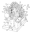
- FIG. 1 shows a perspective view, obliquely from the front/right/above, of a high-performance cutting and turning machine according to the invention for machining spectacle lenses, which is equipped in tool terms with a cutting unit and two fast tool arrangements which form a turning unit, wherein the latter is assigned a first workpiece spindle unit while the cutting unit is assigned a second workpiece spindle unit;
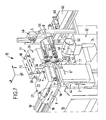
- FIG. 2 shows a perspective view, obliquely from the front/right/above, of the machine of FIG. 1 with an additionally provided loading device for the workpiece changeover operation;
- FIG. 3 shows a front view of the machine of FIG. 2 ;
- FIG. 4 shows a side view of the machine of FIG. 2 , from the left in FIG. 3 ;
- FIG. 5 shows a plan view of the machine of FIG. 2 , seen from above in FIG. 3 ;
- FIGS. 6 to 10 show perspective views, obliquely from the front/left/above, of the machine of FIG. 2 , which illustrate a workpiece changeover operation;
- FIG. 11 shows a schematic sectional view of the machine of FIG. 2 along the section line XI-XI in FIG. 3 , which illustrates the arrangement of air spring elements for mounting the machining units on a common machine pedestal.
- FIGS. 1 to 11 show in a partially schematic manner a CNC-controlled high-performance cutting and turning machine 10 for machining spectacle lenses L made of plastic in a right-angled Cartesian co-ordinate system, in which the small letters x, y and z respectively denote the width direction (x), the length direction (y) and the height direction (z) of the machine 10 .
- the casings and protective devices of the machine 10 have been omitted in the figures for the sake of clarity.
- the machine 10 comprises a turning unit which is referenced 11 as a whole and a cutting unit which is referenced 12 as a whole, which are isolated from one another in terms of vibration.
- the turning unit 11 comprises a first machine frame 13 which is made of polymer concrete
- the cutting unit 12 comprises a second machine frame 14 which is also made of polymer concrete.
- the first machine frame 13 and the second machine frame 14 which do not make contact with one another, are mounted on a common machine pedestal 16 via suitable vibration decoupling elements, for example air spring elements 15 , such as those available from EFFBE GmbH, Raunheim, Germany under the trade name “Level Mount®”.
- the first machine frame 13 and the second machine frame 14 delimit a common working space 17 , in which both the turning machining and the cutting machining are carried out.
- the first machine frame 13 has an essentially rectangular cross section while the second machine frame 14 has an essentially L-shaped cross section.
- the number and position of the air spring elements 15 by means of which the machine frames 13 , 14 which are spaced apart from one another are supported with respect to the common machine pedestal 16 are in this case selected in such a way that four air spring elements 15 are provided for the first machine frame 13 , said air spring elements being located in the region of the corners of the essentially rectangular cross section of the first machine frame 13 , while three air spring elements 15 are provided for the second machine frame 14 , with one air spring element 15 at the end of each leg of the essentially L-shaped cross section of the second machine frame 14 and one air spring element 15 in the region of the corner formed by the two legs of the cross section.
- the air spring elements 15 for the first machine frame 13 on the one hand and the air spring elements 15 for the second machine frame 14 on the other hand may be different from one another, in particular such that the first machine frame 13 belonging to the turning unit 11 is mounted in a softer manner with respect to the machine pedestal 16 than the second machine frame 14 belonging to the cutting unit 12 .
- the air spring elements 15 may furthermore be connected to a compressed air source (not shown) via associated control valves (also not shown), so that air can optionally be supplied to or discharged from the air spring elements 15 pneumatically in order to maintain a defined position, that is to say operating height, of the respective air spring element 15 under the changing loads which occur during the machining operation carried out by the respective machining unit 11 , 12 .
- machining units 11 , 12 Firstly the turning unit 11 will be described in greater detail.
- two guide rails 18 which extend parallel to one another in the (horizontal) width direction x are fixed to an upper mounting surface of the first machine frame 13 in FIG. 1 .
- An X-slide 19 which can be moved in a CNC-controlled manner in both directions of an X-axis by means of associated CNC drive and control elements (not shown), is displaceably mounted on the guide rails 18 .
- Two further guide rails 20 which extend parallel to one another in the (likewise horizontal) longitudinal direction y and perpendicular to the guide rails 18 , are fixed to an upper mounting surface of the X-slide 19 in FIG. 1 .
- a Y-slide 22 is displaceably mounted on the guide rails 20 in a cross table arrangement, which Y-slide can be moved in a CNC-controlled manner in both directions of a Y-axis by means of associated CNC drive and control elements (also not shown)
- a workpiece spindle 24 Fixed to a lower mounting surface of the Y-slide 22 in FIGS. 1 to 4 is a workpiece spindle 24 which can be driven in rotation about a workpiece rotation axis B by means of an electric motor 26 , at a CNC-controlled rotation speed and rotation angle.
- the workpiece rotation axis B is aligned with the Y-axis.
- the spectacle lens L which is mounted on a block piece is fitted on the workpiece spindle 24 in a manner known per se, or more specifically on the end thereof which projects into the working space 17 , in such a way that said workpiece can rotate in the same axis as the workpiece spindle 24 .
- the workpiece spindle 24 can be moved by means of the cross table arrangement (X-slide 19 , Y-slide 22 ) in a CNC-controlled manner in an X-Y plane which contains the workpiece rotation axis B, while the spectacle lens L can rotate about the workpiece rotation axis B at a CNC-controlled rotation speed and rotation angle.
- These components form a first workpiece spindle unit 27 which is assigned to the turning unit 11 .
- At least one fast tool arrangement in the illustrated example of embodiment two fast tool arrangements 28 , 30 arranged in parallel, is/are provided on the right-hand side of the working space 17 in FIGS. 1 , 2 , 3 and 5 (more than two fast tool arrangements are also conceivable in principle).
- each fast tool arrangement 28 , 30 comprises an actuator 32 , 34 and a respectively associated shuttle 36 , 38 .
- the shuttle 36 of the first fast tool arrangement 28 can be moved axially by means of the actuator 32 in both directions of a fast tool axis F 1
- the shuttle 38 of the second fast tool arrangement 30 can be moved axially by means of the actuator 34 in both directions of a second fast tool axis F 2 which is parallel to the first fast tool axis F 1
- the position and travel of the shuttles 36 , 38 can be controlled independently of one another by means of CNC.
- the fast tool axis F 1 , the fast tool axis F 2 , the Y-axis and the workpiece rotation axis B run in the same direction when seen in plan view.
- the direction of the Y-axis and the workpiece rotation axis B on the one hand differs from the direction of the fast tool axis F 1 and the fast tool axis F 2 on the other hand.
- each of the shuttles 36 , 38 has a turning tool 40 , 42 at its end which projects into the working space 17 (see FIGS. 3 and 5 and 6 to 10 ), said turning tool being fixed to the respective shuttle 36 , 38 in a manner not shown in any greater detail here, so that the turning tools 40 , 42 can be moved in a fast tool movement plane (X-F 1 plane and X-F 2 plane, respectively).
- a cutter disk (not shown in any greater detail) is optionally applied releasably or as a coating to each turning tool 40 , 42 , which cutter disk forms a cutting edge and may consist of polycrystalline diamond (PCD), CVD, natural diamond or else hard metal with or without a wear-resistant coating, depending on the respective requirements, in particular depending specifically on the material to be machined.
- PCD polycrystalline diamond
- CVD chemical vapor deposition
- natural diamond or else hard metal with or without a wear-resistant coating
- the prescription surface of the spectacle lens L which has been pre-machined by the cutting unit 12 can be post-machined by turning, and this takes place by controlling the movement of the spectacle lens L in the X-axis and optionally the Y-axis, that is to say in the X-Y plane, and by controlling the movement of the machining turning tool 40 (or 42 ) in the F 1 axis (or F 2 axis), that is to say in the X-F 1 plane (or X-F 2 plane).
- the fast tool arrangements 28 and 30 can be (but do not have to be) actuated in such a way that the shuttle which is not involved in the turning machining operation moves in the opposite direction to the shuttle which is involved in the turning machining operation, so that the shuttles move virtually in opposite directions so as to prevent or reduce, due to mass compensation, the transmission of disruptive vibrations into the first machine frame 13 , as disclosed in WO 02/06005 A1.
- surface qualities can be achieved which are almost the same as the surface qualities which can be achieved by means of conventional polishing processes.
- a special feature of the above-described machine 10 also consists in that, as already mentioned above in a more general manner, the fast tool arrangements 28 and 30 are mounted on a mounting surface of the first machine frame 13 which is tilted or placed at an angle ⁇ (see FIG. 3 ) with respect to the mounting surfaces for the cross table arrangement (X-slide 19 , Y-slide 22 ) and the workpiece spindle 24 , so that the fast tool movement plane (X-F 1 plane or X-F 2 plane) is at an angle with respect to the movement plane (X-Y plane) of the workpiece spindle 24 which contains the workpiece rotation axis B.
- this angle ⁇ is approximately 5°, but may also be slightly greater or slightly smaller, for example may lie within the range from 2° to 10°.
- a movement of the turning tool 40 by means of the fast tool arrangement 28 in the F 1 axis or a movement of the turning tool 42 by means of the fast tool arrangement 30 in the F 2 axis results in two movement components being impressed on the movement of the respective cutting edge, namely a movement component in the longitudinal direction y of the machine 10 and a movement component in the height direction z of the machine 10 .
- the latter can be used to align the working point of the cutting edge of the respective turning tool 40 , 42 with the workpiece rotation axis B of the workpiece spindle 24 , in order to compensate height errors or differences of the cutting edge in the height direction z.
- the cutting unit 12 will now be discussed, to the extent which appears necessary for an understanding of the present invention.
- the cutting unit 12 is assigned a second workpiece spindle unit 44 which is mounted on the second machine frame 14 , as can be seen in particular from FIGS. 4 and 6 to 10 . Since the second workpiece spindle unit 44 corresponds in principle to the first workpiece spindle unit 27 in terms of its structure and function—it is even possible to use identical parts (e.g. guide rails, slides, workpiece spindles, drives and control elements) for the two workpiece spindle units—it will be discussed here only in respect of its particular features.
- the second workpiece spindle unit 44 which by means of its cross table arrangement allows a movement of the workpiece spindle 24 ′ in a CNC-controlled manner in the axes Y′ and Z in a Y′-Z plane which contains the workpiece rotation axis B′ of the workpiece spindle 24 ′, while the spectacle lens L′ can be rotated about the workpiece rotation axis B′ at a CNC-controlled rotation speed and rotation angle—is oriented perpendicular to the first workpiece spindle unit 27 which in the illustrated example of embodiment runs horizontally, so that the respective movement planes (X-Y plane and Y′-Z plane) of the workpiece spindles 24 , 24 ′ run perpendicular to one another.
- a cutter spindle unit 48 is mounted on an upper surface of the second machine frame 14 in front of the working space 17 , the structure and function of said cutter spindle unit being known in principle from EP 0 758 571 A1 by the Applicant.
- the cutter spindle unit 48 comprises a cutter spindle 52 which can be driven about a cutter rotation axis C at a controlled rotation speed by means of an electric motor 50 , a cutting tool 54 being mounted at the end of said cutter spindle which projects into the working space 17 .
- the cutter spindle unit 48 By means of the cutter spindle unit 48 , it is possible to carry out on the spectacle lens L 1 a cutting machining operation which—according to the teaching of EP 0 758 571 A1—comprises a grooving step in which the cutting tool 54 rotating about the cutter rotation axis C at a controlled rotation speed and the spectacle lens L′ rotating about the workpiece rotation axis B′ at a controlled rotation angle are moved relative to one another in a positionally controlled manner in at least one of the two axis directions Y′ and Z in such a way that the cutting edges of the cutting tool 54 produce an annular, trough-like recess at least in the region of the outer edge of the spectacle lens L′, before the cutting tool 54 is guided over the spectacle lens L′ from the outside inwards in a shaping operation along a spiral-shaped path by controlling the movement path of the spectacle lens L 1 in the Y′—and Z-axes, that is to say in the Y′-Z plane, so as to remove further material
- steps which are carried out during this cutting machining operation include edge machining and faceting of the spectacle lens L′.
- edge machining machining of the spectacle lens blank is carried out for example to the outer contour defined by the shape of the spectacle frame, by means of the rotating cutting tool 54 , whereas, during faceting, the upper and/or inner peripheral edge of the spectacle lens blank is bevelled or rounded by means of the rotating cutting tool 54 .
- fast tool fine turning machining of spectacle lenses is an ultraprecise turning process which reacts very sensitively to external vibrations.
- the required precision of the turned spectacle lens surfaces lies in the sub-micrometre range and the Ra values lie in the two-figure nanometre range.
- a not inconsiderable mass of the second workpiece spindle unit 44 of approximately 80 kg moves at relatively high accelerations and distances of up to 14 mm, which in turn leads to vibrations in the second machine frame 14 .
- These disruptive vibrations must be kept away from the turning unit 11 during the fine turning of the optical surface.
- the aforementioned air spring elements 15 are provided as vibration-absorbing means between the common machine pedestal 16 and the machine frames 13 , 14 of the turning unit 11 and cutting unit 12 .
- a loading device 46 is provided as the handling system for loading and unloading purposes, which loading device will now be explained in more detail with reference to FIGS. 6 to 10 .
- the loading device 46 operates by means of three suction cups 58 —referred to together as suction head 59 for short—which can be extended in the axial direction via cylinders 57 and are arranged on a common rotating disk 56 , which suction cups can simultaneously hold the blank, the cut lens and the turned lens.
- suction head 59 merely has to move towards the two parallel workpiece holders on the workpiece spindles 24 , 24 ′, remove the machined lenses, index them and then place the blank into the holder on the workpiece spindle 24 ′ of the cutter unit 12 and the cut lens into the holder on the workpiece spindle 24 of the turning unit 11 .
- the protective device (not shown in the figures) of the machine 10 closes and the cutting and turning machining of the two lenses starts.
- the suction head 59 deposits the machined lens in a working box 60 and picks up a new blank for the next machining operation, and then the suction head 59 is moved to a waiting position.
- another loading and unloading operation takes place. This loading and unloading operation is shown in more detail in FIGS. 2 and 6 to 10 .
- the semi-finished part (shown by right-sloping hatching) is held on the workpiece spindle 24 ′ of the cutting unit 12
- the finished part (shown by cross-hatching) is held on the workpiece spindle 24 of the turning unit 11 .
- Both workpiece spindles 24 , 24 ′ are located in the loading/unloading position, as can be seen from the position in the x-direction (workpiece spindle 24 ) and in the z-direction (workpiece spindle 24 ′).
- the working box 60 containing the blank (not hatched) is in the position for loading and unloading.
- a cylinder 57 is located above the blank, extends outwards and picks up the blank with its suction cup 58 by means of vacuum. The cylinder 57 then retracts again. Thereafter, the suction head 59 is pivoted through 90° about a pivot axis S into the working space 17 . Once the 90° position has been reached, the two left-hand cylinders 57 of the suction head 59 in FIG. 7 are in an axially aligned position with respect to the workpiece rotation axes B, B′ of the workpiece spindles 24 , 24 ′ of the turning unit 11 and of the cutting unit 12 . All the cylinders 57 are extended.
- the workpiece spindles 24 , 24 ′ are then moved in the direction of the suction head 59 by means of corresponding actuation of the Y-axis of the first workpiece spindle unit 27 and of the Y′-axis of the second workpiece spindle unit 44 , as shown in FIG. 8 .
- the suction cups 58 on the respective cylinders 57 are then located on the semi-finished part and finished part.
- the semi-finished part and the finished part are then picked up by the suction cups 58 , whereupon the workpiece spindles 24 , 24 ′, following detachment of the workpieces, are moved back again by actuation in the Y-axis and the Y′-axis.
- the semi-finished part and the finished part are then held on the suction cups 58 ( FIG. 9 ).
- the rotating disk 56 is then rotated through 120° about its rotation axis D. While the blank reaches the position of the workpiece rotation axis B′ of the cutting unit 12 , the semi-finished part reaches the position of the workpiece rotation axis B of the turning unit 11 . At the same time, the finished part is pivoted from the position of the workpiece rotation axis B of the turning unit 11 to the “free” position.
- the blank can then be placed onto the workpiece spindle 24 ′ of the cutting unit 12 and at the same time the semi-finished part can be placed onto the workpiece spindle 24 of the turning unit 11 , and for this the Y-axis and Y′-axis are actuated accordingly.
- the Y- and Y′-axes are moved back, resulting in the state shown in FIG. 10 .
- the cylinders 57 are then retracted and the suction head 59 is moved out of the working space 17 by pivoting about the pivot axis S, so that the finished part—by means of corresponding actuation of the cylinder 57 —can be deposited in the working box 60 while the blank is being machined by cutting in the cutting unit 12 and the semi-finished part is being machined by turning in the turning unit 11 .
- the loading and unloading operation can start again.
- a new working box 60 is moved below the suction head 59 by means of a conveyor belt 62 of the loading device 46 , while the old working box 60 is at the same time moved away from the loading/unloading position by the conveyor belt 62 .
- a method for machining particularly spectacle lenses by means of a machine which comprises at least one cutting unit and at least one turning unit in a common working space, wherein at least two spectacle lenses are machined at the same time in the working space, one of said spectacle lenses being cut while the other is turned.
- Further aspects of the proposed machine consist in that the machine frames of the cutting unit and of the turning unit are essentially decoupled from one another in terms of vibration and/or at least two machining units of the machine comprise workpiece spindle units for generating a transverse movement of the spectacle lens to be machined with respect to the respective tool, said workpiece spindle units being arranged essentially perpendicular to one another.
Applications Claiming Priority (3)
| Application Number | Priority Date | Filing Date | Title |
|---|---|---|---|
| DE102005021639 | 2005-05-06 | ||
| DE102005021639.0 | 2005-05-06 | ||
| DE102005021639A DE102005021639A1 (de) | 2005-05-06 | 2005-05-06 | Hochleistungs-Fräs- und Drehmaschine sowie Verfahren zur Bearbeitung von Brillengläsern |
Publications (2)
| Publication Number | Publication Date |
|---|---|
| US20060260448A1 US20060260448A1 (en) | 2006-11-23 |
| US7739778B2 true US7739778B2 (en) | 2010-06-22 |
Family
ID=36764435
Family Applications (1)
| Application Number | Title | Priority Date | Filing Date |
|---|---|---|---|
| US11/415,334 Expired - Fee Related US7739778B2 (en) | 2005-05-06 | 2006-05-01 | High-performance cutting and turning machine and method for machining particularly spectacle lenses |
Country Status (7)
| Country | Link |
|---|---|
| US (1) | US7739778B2 (zh) |
| EP (1) | EP1719582B1 (zh) |
| JP (1) | JP2006312234A (zh) |
| CN (1) | CN100532007C (zh) |
| AT (1) | ATE419091T1 (zh) |
| BR (1) | BRPI0601623A (zh) |
| DE (2) | DE102005021639A1 (zh) |
Cited By (10)
| Publication number | Priority date | Publication date | Assignee | Title |
|---|---|---|---|---|
| US20100224039A1 (en) * | 2009-03-04 | 2010-09-09 | Schneider Gmbh & Co. Kg | Lathe for manufacturing ophthalmic lenses made of plastic |
| US20120240736A1 (en) * | 2009-12-21 | 2012-09-27 | Essilor International (Compagnie Generale D'optique) | Machining method by turning a face of a spectacle lens |
| CN103567762A (zh) * | 2013-10-29 | 2014-02-12 | 芜湖陀曼精机科技有限公司 | 一种数控车磨复合机床 |
| US9321145B2 (en) | 2012-03-10 | 2016-04-26 | Satisloh Ag | Device for fine machining of optically effective surfaces on in particular spectacle lenses and flexible production cell comprising such a device |
| US20160161044A1 (en) * | 2014-12-09 | 2016-06-09 | Caterpillar Inc. | Base for power source components |
| US9427844B2 (en) * | 2012-05-22 | 2016-08-30 | Satisloh Ag | Centering machine for workpieces, particularly optical lenses |
| US10406646B2 (en) | 2011-03-01 | 2019-09-10 | Schneider Gmbh & Co. Kg | Device and method for machining of an optical lens |
| US20200023478A1 (en) * | 2016-09-30 | 2020-01-23 | Komatsu Ntc Ltd. | Machine tool bed and machine tool |
| US11130223B2 (en) * | 2017-10-30 | 2021-09-28 | Pearson Packaging Systems | Base for a robotic arm |
| US11583971B2 (en) | 2016-06-07 | 2023-02-21 | Satisloh Ag | Machine for machining workpieces with optical quality |
Families Citing this family (22)
| Publication number | Priority date | Publication date | Assignee | Title |
|---|---|---|---|---|
| ATE430641T1 (de) * | 2006-10-26 | 2009-05-15 | Satisloh Ag | Maschine zur bearbeitung von optischen werkstücken, insbesondere von kunststoff- brillengläsern |
| DE102007031703A1 (de) * | 2007-07-06 | 2009-01-08 | Satisloh Gmbh | Maschine zur Bearbeitung von optischen Werkstücken, insbesondere von Kunststoff-Brillengläsern |
| CN103003041A (zh) * | 2010-04-29 | 2013-03-27 | 牙科实验室铣床用品有限责任公司 | 用于由坯料生产产品的方法、系统和装置 |
| DE102011110834A1 (de) * | 2011-08-23 | 2013-02-28 | Kern Micro- Und Feinwerktechnik Gmbh & Co. Kg | Maschinenständer einer Werkzeugmaschine |
| FR2979558B1 (fr) * | 2011-09-01 | 2013-10-04 | Essilor Int | Procede de surfacage d'une surface d'un verre de lunettes |
| CN102699770B (zh) * | 2012-04-24 | 2014-08-13 | 浙江日科自动化设备有限公司 | 五轴机 |
| CN102699349B (zh) * | 2012-04-24 | 2014-07-02 | 浙江日科自动化设备有限公司 | 车片机 |
| US9539684B2 (en) * | 2013-03-15 | 2017-01-10 | Microlution Inc. | Micro turning machine |
| DE102014113421B4 (de) | 2014-09-17 | 2016-07-28 | Optotech Optikmaschinen Gmbh | Simultan-Drehmaschine für die Brillenglasfertigung |
| DE102015102899B4 (de) | 2015-02-27 | 2018-02-01 | Optotech Optikmaschinen Gmbh | Fräsvorrichtung für die Brillenglasfertigung mit zwei Frässtationen |
| DE102015102900A1 (de) | 2015-02-27 | 2016-09-01 | Optotech Optikmaschinen Gmbh | Simultan-Drehmaschine für die Brillenglasfertigung |
| CN105345575B (zh) * | 2015-10-08 | 2017-09-22 | 北京工业大学 | 眼镜片铣边机自动上下料传动装置 |
| DE102015120853B3 (de) * | 2015-12-01 | 2017-04-27 | Friedrich-Schiller-Universität Jena | Verfahren und Vorrichtung zur Herstellung eines optischen Bauteils mit mindestens drei monolithisch angeordneten optischen Funktionsflächen und optisches Bauteil |
| CN110270906B (zh) * | 2019-07-25 | 2020-04-03 | 杭州幕林眼镜有限公司 | 一种光学透镜弧形镜壁加工装置 |
| JP7144396B2 (ja) * | 2019-12-25 | 2022-09-29 | 旭化成ワッカーシリコーン株式会社 | シリコーン消泡剤組成物、および、シリコーン消泡剤組成物の製造方法。 |
| EP3950223A1 (en) * | 2020-08-07 | 2022-02-09 | Schneider GmbH & Co. KG | Apparatus and method for processing optical workpieces |
| USD947261S1 (en) * | 2021-04-22 | 2022-03-29 | Ting He | Double cup turner |
| USD947263S1 (en) * | 2021-05-13 | 2022-03-29 | Ting He | Cup turner |
| US20230150078A1 (en) * | 2021-11-12 | 2023-05-18 | Schneider Gmbh & Co. Kg | Processing apparatus for optical workpieces as well as use of a double gripper |
| CN115200476B (zh) * | 2022-07-15 | 2023-03-10 | 茉丽特科技(深圳)有限公司 | 基于远心镜头的车刀磨损检测装置 |
| CN115647400B (zh) * | 2022-11-07 | 2023-06-23 | 吉林省威创机电工程有限公司 | 一种车床加工用铁屑毛刺去除器 |
| CN117283442B (zh) * | 2023-11-24 | 2024-01-19 | 金昌镒康科技铸业有限公司 | 一种炉盆抛光设备 |
Citations (22)
| Publication number | Priority date | Publication date | Assignee | Title |
|---|---|---|---|---|
| US2994164A (en) | 1960-07-08 | 1961-08-01 | American Optical Corp | Method and apparatus for simultaneously grinding lenses |
| DD120146A1 (zh) | 1975-06-04 | 1976-06-05 | ||
| JPS59232758A (ja) | 1983-06-13 | 1984-12-27 | Matsushita Electric Ind Co Ltd | 球面加工装置 |
| US4520596A (en) | 1982-03-26 | 1985-06-04 | Societe Anonyme Dite: Etudes Et Fabrications Optiques | Grinding or polishing machine for optical lenses |
| FR2575101A1 (fr) | 1984-12-26 | 1986-06-27 | Procedes Fabrication Optiques | Outil pour l'usinage de surfaces optiques et machine utilisant un tel outil |
| US4662119A (en) | 1984-07-25 | 1987-05-05 | Haruchika Precision Company, Ltd. | Automatic lens grinding apparatus |
| US4829716A (en) | 1985-10-22 | 1989-05-16 | Matsushita Electric Industrial Co. Ltd. | Apparatus for automatically performing plural sequential spherical grinding operations on workpieces |
| US5168609A (en) * | 1987-12-24 | 1992-12-08 | Yamazaki Mazik Corp. | Workpiece support for a turret on a opposed spindle lathe |
| US5313694A (en) * | 1992-01-24 | 1994-05-24 | Takisawa Machine Tool Co., Ltd. | Machine tool for non-circular and other machining |
| EP0882548A2 (de) | 1997-06-06 | 1998-12-09 | NILES-SIMMONS Industrieanlagen GmbH | CNC Dreh- und Fräsbearbeitungszentrum |
| US5919013A (en) * | 1995-11-21 | 1999-07-06 | Micro Optics Design Corporation | Opthalmic lens generating apparatus having vibration dampening structure |
| WO1999033611A1 (en) | 1997-12-29 | 1999-07-08 | Massachusetts Institute Of Technology | Precision high speed turning machine |
| US5938381A (en) | 1995-08-12 | 1999-08-17 | Loh Optikmaschinen Ag | Method and tool for creating a concave surface from a spectacle blank |
| US6161457A (en) * | 1998-01-30 | 2000-12-19 | J.G. Weisser Sohne Werkzeugmaschinenfabrik GmbH & Co. KG | Machine tool |
| US20010042424A1 (en) * | 1998-09-04 | 2001-11-22 | Sheehan | Reduced vibration lathe |
| US20020006764A1 (en) | 2000-06-26 | 2002-01-17 | Loh Optikmaschinen Ag | Device for machining optical workpieces |
| WO2002006005A1 (en) | 2000-07-13 | 2002-01-24 | Micro Optics Design Corporation | Lens lathe with vibration cancelling arrangement |
| US6695295B2 (en) * | 2000-11-15 | 2004-02-24 | R.M. Wade & Co. | Vibration-isolating device |
| US6731372B2 (en) * | 2001-03-27 | 2004-05-04 | Nikon Corporation | Multiple chamber fluid mount |
| US6991525B2 (en) | 2001-09-06 | 2006-01-31 | Loh Optikmaschinen Ag | Method and device for the surface machining of workpieces composed of non-brittle materials in optical lens manufacturing and tool for this purpose |
| US7125211B2 (en) * | 2003-10-17 | 2006-10-24 | Racer Machinery International Inc. | Apparatus and method for damping vibration in a machine tool |
| US7219407B2 (en) * | 2003-10-14 | 2007-05-22 | Schneider Gmbh & Co. Kg | Device for milling and lathing |
-
2005
- 2005-05-06 DE DE102005021639A patent/DE102005021639A1/de not_active Withdrawn
-
2006
- 2006-03-29 AT AT06006510T patent/ATE419091T1/de not_active IP Right Cessation
- 2006-03-29 EP EP06006510A patent/EP1719582B1/de active Active
- 2006-03-29 DE DE502006002468T patent/DE502006002468D1/de active Active
- 2006-04-27 CN CNB2006100799132A patent/CN100532007C/zh not_active Expired - Fee Related
- 2006-05-01 US US11/415,334 patent/US7739778B2/en not_active Expired - Fee Related
- 2006-05-08 JP JP2006128909A patent/JP2006312234A/ja active Pending
- 2006-05-08 BR BRPI0601623-5A patent/BRPI0601623A/pt not_active IP Right Cessation
Patent Citations (22)
| Publication number | Priority date | Publication date | Assignee | Title |
|---|---|---|---|---|
| US2994164A (en) | 1960-07-08 | 1961-08-01 | American Optical Corp | Method and apparatus for simultaneously grinding lenses |
| DD120146A1 (zh) | 1975-06-04 | 1976-06-05 | ||
| US4520596A (en) | 1982-03-26 | 1985-06-04 | Societe Anonyme Dite: Etudes Et Fabrications Optiques | Grinding or polishing machine for optical lenses |
| JPS59232758A (ja) | 1983-06-13 | 1984-12-27 | Matsushita Electric Ind Co Ltd | 球面加工装置 |
| US4662119A (en) | 1984-07-25 | 1987-05-05 | Haruchika Precision Company, Ltd. | Automatic lens grinding apparatus |
| FR2575101A1 (fr) | 1984-12-26 | 1986-06-27 | Procedes Fabrication Optiques | Outil pour l'usinage de surfaces optiques et machine utilisant un tel outil |
| US4829716A (en) | 1985-10-22 | 1989-05-16 | Matsushita Electric Industrial Co. Ltd. | Apparatus for automatically performing plural sequential spherical grinding operations on workpieces |
| US5168609A (en) * | 1987-12-24 | 1992-12-08 | Yamazaki Mazik Corp. | Workpiece support for a turret on a opposed spindle lathe |
| US5313694A (en) * | 1992-01-24 | 1994-05-24 | Takisawa Machine Tool Co., Ltd. | Machine tool for non-circular and other machining |
| US5938381A (en) | 1995-08-12 | 1999-08-17 | Loh Optikmaschinen Ag | Method and tool for creating a concave surface from a spectacle blank |
| US5919013A (en) * | 1995-11-21 | 1999-07-06 | Micro Optics Design Corporation | Opthalmic lens generating apparatus having vibration dampening structure |
| EP0882548A2 (de) | 1997-06-06 | 1998-12-09 | NILES-SIMMONS Industrieanlagen GmbH | CNC Dreh- und Fräsbearbeitungszentrum |
| WO1999033611A1 (en) | 1997-12-29 | 1999-07-08 | Massachusetts Institute Of Technology | Precision high speed turning machine |
| US6161457A (en) * | 1998-01-30 | 2000-12-19 | J.G. Weisser Sohne Werkzeugmaschinenfabrik GmbH & Co. KG | Machine tool |
| US20010042424A1 (en) * | 1998-09-04 | 2001-11-22 | Sheehan | Reduced vibration lathe |
| US20020006764A1 (en) | 2000-06-26 | 2002-01-17 | Loh Optikmaschinen Ag | Device for machining optical workpieces |
| WO2002006005A1 (en) | 2000-07-13 | 2002-01-24 | Micro Optics Design Corporation | Lens lathe with vibration cancelling arrangement |
| US6695295B2 (en) * | 2000-11-15 | 2004-02-24 | R.M. Wade & Co. | Vibration-isolating device |
| US6731372B2 (en) * | 2001-03-27 | 2004-05-04 | Nikon Corporation | Multiple chamber fluid mount |
| US6991525B2 (en) | 2001-09-06 | 2006-01-31 | Loh Optikmaschinen Ag | Method and device for the surface machining of workpieces composed of non-brittle materials in optical lens manufacturing and tool for this purpose |
| US7219407B2 (en) * | 2003-10-14 | 2007-05-22 | Schneider Gmbh & Co. Kg | Device for milling and lathing |
| US7125211B2 (en) * | 2003-10-17 | 2006-10-24 | Racer Machinery International Inc. | Apparatus and method for damping vibration in a machine tool |
Cited By (14)
| Publication number | Priority date | Publication date | Assignee | Title |
|---|---|---|---|---|
| US20100224039A1 (en) * | 2009-03-04 | 2010-09-09 | Schneider Gmbh & Co. Kg | Lathe for manufacturing ophthalmic lenses made of plastic |
| US8683897B2 (en) * | 2009-03-04 | 2014-04-01 | Schneider Gmbh & Co. Kg | Lathe for manufacturing ophthalmic lenses made of plastic |
| US9261876B2 (en) * | 2009-12-21 | 2016-02-16 | Essilor International (Compagnie Generale D'optique) | Machining method by turning a face of a spectacle lens |
| US20120240736A1 (en) * | 2009-12-21 | 2012-09-27 | Essilor International (Compagnie Generale D'optique) | Machining method by turning a face of a spectacle lens |
| US10406646B2 (en) | 2011-03-01 | 2019-09-10 | Schneider Gmbh & Co. Kg | Device and method for machining of an optical lens |
| US9321145B2 (en) | 2012-03-10 | 2016-04-26 | Satisloh Ag | Device for fine machining of optically effective surfaces on in particular spectacle lenses and flexible production cell comprising such a device |
| US9427844B2 (en) * | 2012-05-22 | 2016-08-30 | Satisloh Ag | Centering machine for workpieces, particularly optical lenses |
| US10625398B2 (en) | 2012-05-22 | 2020-04-21 | Satisloh Ag | Centering machine for workpieces, particularly optical lenses |
| CN103567762B (zh) * | 2013-10-29 | 2016-09-14 | 芜湖陀曼精机科技有限公司 | 一种数控车磨复合机床 |
| CN103567762A (zh) * | 2013-10-29 | 2014-02-12 | 芜湖陀曼精机科技有限公司 | 一种数控车磨复合机床 |
| US20160161044A1 (en) * | 2014-12-09 | 2016-06-09 | Caterpillar Inc. | Base for power source components |
| US11583971B2 (en) | 2016-06-07 | 2023-02-21 | Satisloh Ag | Machine for machining workpieces with optical quality |
| US20200023478A1 (en) * | 2016-09-30 | 2020-01-23 | Komatsu Ntc Ltd. | Machine tool bed and machine tool |
| US11130223B2 (en) * | 2017-10-30 | 2021-09-28 | Pearson Packaging Systems | Base for a robotic arm |
Also Published As
| Publication number | Publication date |
|---|---|
| CN1857852A (zh) | 2006-11-08 |
| BRPI0601623A (pt) | 2006-12-26 |
| DE102005021639A1 (de) | 2006-11-09 |
| US20060260448A1 (en) | 2006-11-23 |
| EP1719582B1 (de) | 2008-12-31 |
| CN100532007C (zh) | 2009-08-26 |
| ATE419091T1 (de) | 2009-01-15 |
| EP1719582A1 (de) | 2006-11-08 |
| DE502006002468D1 (de) | 2009-02-12 |
| JP2006312234A (ja) | 2006-11-16 |
Similar Documents
| Publication | Publication Date | Title |
|---|---|---|
| US7739778B2 (en) | High-performance cutting and turning machine and method for machining particularly spectacle lenses | |
| US7597033B2 (en) | Machine for machining optical workpieces, in particular plastic spectacle lenses | |
| US5951376A (en) | Procedure of and device for processing optical lenses | |
| US9751171B2 (en) | Method to process spectacle lens blanks | |
| US6431954B1 (en) | Method and apparatus for grinding workpieces with precision work performed at the same time as the grinding | |
| US10537944B2 (en) | Milling device for optical lens production with two milling stations and method of use | |
| US6991525B2 (en) | Method and device for the surface machining of workpieces composed of non-brittle materials in optical lens manufacturing and tool for this purpose | |
| CN101422819B (zh) | 精密轧辊车床 | |
| KR20100092873A (ko) | 렌즈의 가공방법 및 연삭장치 | |
| CA2205292A1 (en) | Support for optical lenses and method for polishing lenses | |
| CN101626868A (zh) | 用于成形眼镜片的机器,该机器设有其上安装多个加工工具的工具托架 | |
| CN1273254C (zh) | 锯片磨快机械 | |
| KR20000076987A (ko) | 피가공물 연삭방법 및 장치 | |
| CN108788628B (zh) | 曲面cd纹理的加工方法 | |
| JP2008034776A (ja) | ワークのエッジの加工方法及び装置 | |
| CN102922385A (zh) | 多重分离自动薄板玻璃加工装置及其制造钢化玻璃的方法 | |
| US10022800B2 (en) | Simultaneous turning device for fabrication of eyeglass lenses | |
| CN212946968U (zh) | 一种曲轴外轮廓精加工设备 | |
| US5154020A (en) | Spherical surface machining apparatus and transporting apparatus therefor | |
| US20230150078A1 (en) | Processing apparatus for optical workpieces as well as use of a double gripper | |
| CN219582368U (zh) | 一种数控外圆磨削抛光机 | |
| JP2012143865A (ja) | ワークのエッジの加工方法および加工装置 | |
| CN114559304B (zh) | 大型陶瓷圆弧加工方法 | |
| Yamamoto et al. | Development of cross and parallel mode grinding machine for high NA aspherical mold and die | |
| KENNEDY | Turning |
Legal Events
| Date | Code | Title | Description |
|---|---|---|---|
| AS | Assignment |
Owner name: SATISLOH GMBH,GERMANY Free format text: ASSIGNMENT OF ASSIGNORS INTEREST;ASSIGNORS:FIEDLER, UDO;HANISCH, MANFRED;TROSS, KARL-HEINZ;AND OTHERS;SIGNING DATES FROM 20060517 TO 20060520;REEL/FRAME:017986/0820 Owner name: SATISLOH GMBH, GERMANY Free format text: ASSIGNMENT OF ASSIGNORS INTEREST;ASSIGNORS:FIEDLER, UDO;HANISCH, MANFRED;TROSS, KARL-HEINZ;AND OTHERS;REEL/FRAME:017986/0820;SIGNING DATES FROM 20060517 TO 20060520 |
|
| SULP | Surcharge for late payment | ||
| FPAY | Fee payment |
Year of fee payment: 4 |
|
| FEPP | Fee payment procedure |
Free format text: MAINTENANCE FEE REMINDER MAILED (ORIGINAL EVENT CODE: REM.) |
|
| LAPS | Lapse for failure to pay maintenance fees |
Free format text: PATENT EXPIRED FOR FAILURE TO PAY MAINTENANCE FEES (ORIGINAL EVENT CODE: EXP.) |
|
| STCH | Information on status: patent discontinuation |
Free format text: PATENT EXPIRED DUE TO NONPAYMENT OF MAINTENANCE FEES UNDER 37 CFR 1.362 |
|
| FP | Lapsed due to failure to pay maintenance fee |
Effective date: 20180622 |