US7715112B2 - Zoom lens system and image pickup apparatus including the same - Google Patents
Zoom lens system and image pickup apparatus including the same Download PDFInfo
- Publication number
- US7715112B2 US7715112B2 US12/186,412 US18641208A US7715112B2 US 7715112 B2 US7715112 B2 US 7715112B2 US 18641208 A US18641208 A US 18641208A US 7715112 B2 US7715112 B2 US 7715112B2
- Authority
- US
- United States
- Prior art keywords
- lens
- lens unit
- wide
- zoom
- object side
- Prior art date
- Legal status (The legal status is an assumption and is not a legal conclusion. Google has not performed a legal analysis and makes no representation as to the accuracy of the status listed.)
- Expired - Fee Related, expires
Links
Images


Classifications
-
- G—PHYSICS
- G02—OPTICS
- G02B—OPTICAL ELEMENTS, SYSTEMS OR APPARATUS
- G02B27/00—Optical systems or apparatus not provided for by any of the groups G02B1/00 - G02B26/00, G02B30/00
- G02B27/64—Imaging systems using optical elements for stabilisation of the lateral and angular position of the image
- G02B27/646—Imaging systems using optical elements for stabilisation of the lateral and angular position of the image compensating for small deviations, e.g. due to vibration or shake
-
- G—PHYSICS
- G02—OPTICS
- G02B—OPTICAL ELEMENTS, SYSTEMS OR APPARATUS
- G02B15/00—Optical objectives with means for varying the magnification
- G02B15/14—Optical objectives with means for varying the magnification by axial movement of one or more lenses or groups of lenses relative to the image plane for continuously varying the equivalent focal length of the objective
- G02B15/144—Optical objectives with means for varying the magnification by axial movement of one or more lenses or groups of lenses relative to the image plane for continuously varying the equivalent focal length of the objective having four groups only
- G02B15/1441—Optical objectives with means for varying the magnification by axial movement of one or more lenses or groups of lenses relative to the image plane for continuously varying the equivalent focal length of the objective having four groups only the first group being positive
- G02B15/144113—Optical objectives with means for varying the magnification by axial movement of one or more lenses or groups of lenses relative to the image plane for continuously varying the equivalent focal length of the objective having four groups only the first group being positive arranged +-++
Definitions
- the present invention relates to zoom lens systems and image pickup apparatuses including the same suitable for video cameras, digital still cameras, broadcast cameras, silver-halide-film cameras, and the like.
- Recent image pickup apparatuses such as cameras including video cameras, digital still cameras, broadcast cameras having solid-state image pickup devices and cameras used with silver-halide films, have high functionality and are of small size.
- Zoom lens systems serving as image taking optical systems to be included in such image pickup apparatuses are desired to be compact with a short total length and a high resolution.
- zoom lens systems are desired to have a wide angle of view and a high zoom ratio.
- a known four-unit zoom lens system that includes four lens units, in which a first lens unit having a positive optical power, a second lens unit having a negative optical power, a third lens unit having a positive optical power, and a fourth lens unit having a positive optical power are arranged in that order from an object side to an image side.
- U.S. Pat. No. 7,333,274 and Japanese Patent Laid-Open No. 8-50244 disclose rear-focusing four-unit zoom lens systems, in which a first lens unit, a second lens unit, and a third lens unit are moved to change the magnification while a fourth lens unit corrects variations in an image plane caused by the change of magnification and performs focusing.
- US Patent Application Publication No. 2007/0091460 discloses a zoom lens system in which a still image is obtained while the entirety of a third lens unit is shifted in a direction perpendicular to the optical axis.
- the size of a zoom lens system can be reduced by reducing the number of lens elements while increasing the optical power of each of the lens units included in the zoom lens system.
- lens elements of a zoom lens system configured in such a manner tend to become thick because of the increase in the optical power of each of the lens units. Therefore, the total length of the zoom lens system may not be reduced sufficiently and correction of various aberrations may become difficult.
- the present invention provides a zoom lens system of small size capable of realizing high optical performance throughout a zoom range.
- the present invention also provides an image pickup apparatus including such a zoom lens system.
- a zoom lens system includes, in order from an object side to an image side, a first lens unit having a positive optical power, the first lens unit including one negative lens element and two positive lens elements, a second lens unit having a negative optical power, a third lens unit having a positive optical power, and a fourth lens unit having a positive optical power.
- the first lens unit moves during zooming.
- f 1 denotes a focal length of the first lens unit
- st 1 denotes a distance between positions of the first lens unit at a wide-angle end and at a telephoto end
- fw and ft denote focal lengths of the entire system at the wide-angle end and at the telephoto end, respectively
- ⁇ 3 W and ⁇ 3 T denote lateral magnifications of the third lens unit at the wide-angle end and at the telephoto end, respectively.
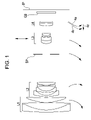
- FIG. 1 is a sectional view of a zoom lens system according to a first embodiment of the present invention at a wide-angle end.
- FIG. 2 is a diagram showing aberrations of the zoom lens system of the first embodiment corresponding to Numerical Example 1 at the wide-angle end.
- FIG. 3 is a diagram showing aberrations of the zoom lens system of the first embodiment corresponding to Numerical Example 1 at an intermediate zoom position.
- FIG. 4 is a diagram showing aberrations of the zoom lens system of the first embodiment corresponding to Numerical Example 1 at a telephoto end.
- FIG. 5 is a sectional view of a zoom lens system according to a second embodiment of the present invention at a wide-angle end.
- FIG. 6 is a diagram showing aberrations of the zoom lens system of the second embodiment corresponding to Numerical Example 2 at the wide-angle end.
- FIG. 7 is a diagram showing aberrations of the zoom lens system of the second embodiment corresponding to Numerical Example 2 at an intermediate zoom position.
- FIG. 8 is a diagram showing aberrations of the zoom lens system of the second embodiment corresponding to Numerical Example 2 at a telephoto end.
- FIG. 9 is a sectional view of a zoom lens system according to a third embodiment of the present invention at a wide-angle end.
- FIG. 10 is a diagram showing aberrations of the zoom lens system of the third embodiment corresponding to Numerical Example 3 at the wide-angle end.
- FIG. 11 is a diagram showing aberrations of the zoom lens system of the third embodiment corresponding to Numerical Example 3 at an intermediate zoom position.
- FIG. 12 is a diagram showing aberrations of the zoom lens system of the third embodiment corresponding to Numerical Example 3 at a telephoto end.
- FIG. 13 is a sectional view of a zoom lens system according to a fourth embodiment of the present invention at a wide-angle end.
- FIG. 14 is a diagram showing aberrations of the zoom lens system of the fourth embodiment corresponding to Numerical Example 4 at the wide-angle end.
- FIG. 15 is a diagram showing aberrations of the zoom lens system of the fourth embodiment corresponding to Numerical Example 4 at an intermediate zoom position.
- FIG. 16 is a diagram showing aberrations of the zoom lens system of the fourth embodiment corresponding to Numerical Example 4 at a telephoto end.
- FIG. 17 is a sectional view of a zoom lens system according to a fifth embodiment of the present invention at a wide-angle end.
- FIG. 18 is a diagram showing aberrations of the zoom lens system of the fifth embodiment corresponding to Numerical Example 5 at the wide-angle end.
- FIG. 19 is a diagram showing aberrations of the zoom lens system of the fifth embodiment corresponding to Numerical Example 5 at an intermediate zoom position.
- FIG. 20 is a diagram showing aberrations of the zoom lens system of the fifth embodiment corresponding to Numerical Example 5 at a telephoto end.
- FIG. 21 is a sectional view of a zoom lens system according to a sixth embodiment of the present invention at a wide-angle end.
- FIG. 22 is a diagram showing aberrations of the zoom lens system of the sixth embodiment corresponding to Numerical Example 6 at the wide-angle end.
- FIG. 23 is a diagram showing aberrations of the zoom lens system of the sixth embodiment corresponding to Numerical Example 6 at an intermediate zoom position.
- FIG. 24 is a diagram showing aberrations of the zoom lens system of the sixth embodiment corresponding to Numerical Example 6 at a telephoto end.
- FIG. 25 is a sectional view of a zoom lens system according to a seventh embodiment of the present invention at a wide-angle end.
- FIG. 26 is a diagram showing aberrations of the zoom lens system of the seventh embodiment corresponding to Numerical Example 7 at the wide-angle end.
- FIG. 27 is a diagram showing aberrations of the zoom lens system of the seventh embodiment corresponding to Numerical Example 7 at an intermediate zoom position.
- FIG. 28 is a diagram showing aberrations of the zoom lens system of the seventh embodiment corresponding to Numerical Example 7 at a telephoto end.
- FIG. 29 schematically shows an image pickup apparatus according to an eighth embodiment of the present invention.
- Zoom lens systems each include, in order from an object side to an image side, a first lens unit having a positive optical power (refractive power), a second lens unit having a negative optical power (refractive power), a third lens unit having a positive optical power, and a fourth lens unit having a positive optical power. At least the first lens unit moves during zooming.
- zooming is performed by moving all of the first to fourth lens units.
- the present invention is not limited to such a configuration. For example, zooming may be performed by moving the first, second, and third lens units; the first, second, and fourth lens units; or the first, third, and fourth lens units.
- FIG. 1 is a sectional view of a zoom lens system according to the first embodiment of the present invention at a wide-angle end (short-focal-length end).
- FIGS. 2 to 4 are diagrams showing aberrations of the zoom lens system according to the first embodiment at the wide-angle end, at an intermediate zoom position, and at a telephoto end (long-focal-length end), respectively.
- FIG. 5 is a sectional view of a zoom lens system according to the second embodiment of the present invention at a wide-angle end.
- FIGS. 6 to 8 are diagrams showing aberrations of the zoom lens system according to the second embodiment at the wide-angle end, at an intermediate zoom position, and at a telephoto end, respectively.
- FIG. 9 is a sectional view of a zoom lens system according to the third embodiment of the present invention at a wide-angle end.
- FIGS. 10 to 12 are diagrams showing aberrations of the zoom lens system according to the third embodiment at the wide-angle end, at an intermediate zoom position, and at a telephoto end, respectively.
- FIG. 13 is a sectional view of a zoom lens system according to the fourth embodiment of the present invention at a wide-angle end.
- FIGS. 14 to 16 are diagrams showing aberrations of the zoom lens system according to the fourth embodiment at the wide-angle end, at an intermediate zoom position, and at a telephoto end, respectively.
- FIG. 17 is a sectional view of a zoom lens system according to the fifth embodiment of the present invention at a wide-angle end.
- FIGS. 18 to 20 are diagrams showing aberrations of the zoom lens system according to the fifth embodiment at the wide-angle end, at an intermediate zoom position, and at a telephoto end, respectively.
- FIG. 21 is a sectional view of a zoom lens system according to the sixth embodiment of the present invention at a wide-angle end.
- FIGS. 22 to 24 are diagrams showing aberrations of the zoom lens system according to the sixth embodiment at the wide-angle end, at an intermediate zoom position, and at a telephoto end, respectively.
- FIG. 25 is a sectional view of a zoom lens system according to the seventh embodiment of the present invention at a wide-angle end.
- FIGS. 26 to 28 are diagrams showing aberrations of the zoom lens system according to the seventh embodiment at the wide-angle end, at an intermediate zoom position, and at a telephoto end, respectively.
- FIG. 29 schematically shows relevant parts of a camera (an image pickup apparatus) that includes the zoom lens system according to any of the embodiments of the present invention.
- the zoom lens systems according to the first to seventh embodiments are image taking lens systems included in image pickup apparatuses such as video cameras, digital still cameras, and silver-halide-film cameras.
- each zoom lens system In the sectional view of each zoom lens system, an object resides on the left (front) side, and an image is formed on the right (rear) side. Further, in the sectional view, i denotes the order of the lens unit counted from the object side. For example, Li denotes the i-th lens unit.
- the zoom lens system includes a first lens unit L 1 having a positive optical power (refractive power, i.e., the reciprocal of a focal length), a second lens unit L 2 having a negative optical power, a third lens unit L 3 having a positive optical power, and a fourth lens unit L 4 having a positive optical power.
- the zoom lens system also includes an aperture stop SP, which is disposed on the object side with respect to the third lens unit L 3 , and an optical block GB, which is a component such as an optical filter, a face plate, a quartz low-pass filter, or an infrared-cut filter.
- An image plane IP functions as a photosensitive plane, which is an equivalent of the image pickup plane of a solid-state image pickup device (photoelectric conversion element) such as a charge-coupled-device (CCD) sensor or a complementary-metal-oxide-semiconductor (CMOS) sensor when the zoom lens system is used as an image taking optical system of a video camera or a digital still camera, or the film surface when the zoom lens system is used in a silver-halide-film camera.
- a solid-state image pickup device photoelectric conversion element
- CCD charge-coupled-device
- CMOS complementary-metal-oxide-semiconductor
- d and g denote the d-line and the g-line, respectively
- ⁇ M and ⁇ S denote the meridional image plane and the sagittal image plane, respectively.
- the lateral chromatic aberration is shown for the g-line.
- ⁇ denotes the half angle of view
- Fno denotes the f-number.
- the wide-angle end and the telephoto end are zoom positions at extreme ends of a range in which magnification-changing lens units can mechanically move along the optical axis.
- the lens units and the aperture stop SP move as indicated by respective arrows during zooming from the wide-angle end to the telephoto end.
- the first lens unit L 1 moves toward the image side first and then toward the object side.
- the first lens unit L 1 moves in such a manner as to be positioned closer to the object side at the telephoto end than at the wide-angle end.
- the second lens unit L 2 moves along a locus convex toward the image side.
- the third lens unit L 3 moves toward the object side.
- the fourth lens unit L 4 moves along a locus convex toward the object side.
- the aperture stop SP moves independently from all of the lens units or together with the third lens unit L 3 toward the object side.
- the first lens unit L 1 and the third lens unit L 3 move in such a manner as to be positioned closer to the object side at the telephoto end than at the wide-angle end.
- the total length of the zoom lens system at the wide-angle end can be maintained to be small while a high zoom ratio can be realized.
- magnification-changing operation is shared between the third lens unit L 3 and the fourth lens unit L 4 .
- the second lens unit L 2 can be made to produce a significant magnification-changing effect.
- a high zoom ratio can be realized without largely increasing the optical powers of the first lens unit L 1 and the second lens unit L 2 .
- the zoom lens system in each embodiment employs a rear-focusing method in which focusing is performed by moving the fourth lens unit L 4 along the optical axis.
- the fourth lens unit L 4 is moved forward as indicated by an arrow 4 c shown in each sectional view.
- a solid curve 4 a and a dotted curve 4 b shown for the fourth lens unit L 4 are loci along which the fourth lens unit L 4 moves to correct variations in the image plane occurring during zooming from the wide-angle end to the telephoto end.
- the solid curve 4 a indicates the case where the focus is on an object at infinity
- the dotted curve 4 b indicates the case where the focus is on a near object.
- the space between the third lens unit L 3 and the fourth lens unit L 4 is efficiently utilized, whereby the total length of the zoom lens system can be reduced effectively.
- the fourth lens unit L 4 which is of small weight, is moved for the purpose of focusing. This facilitates quick focusing. For example, automatic focus detection can be performed quickly.
- the first lens unit L 1 which does not move along the optical axis for the purpose of focusing, may be made to move independently or together with the fourth lens unit L 4 according to need of correction of aberration.
- the position of an image to be taken is corrected by shifting the entirety or a part of the third lens unit L 3 in a direction in which a component perpendicular to the optical axis is produced. That is, image displacement (positional shift of the image plane) is corrected.
- the aperture stop SP moves independently from the lens units during zooming.
- the entrance pupil for wide angles of view is positioned close to the object side, whereby increase in the front lens diameter (the effective diameter of the first lens unit) is suppressed.
- the focal length of the first lens unit L 1 is denoted as f 1
- the distance between the position of the first lens unit L 1 at the wide-angle end and the position of the first lens unit L 1 at the telephoto end is denoted as st 1 .
- the focal lengths of the entire system at the wide-angle end and at the telephoto end are denoted as fw and ft, respectively, and the lateral magnifications of the third lens unit L 3 at the wide-angle end and at the telephoto end are denoted as ⁇ 3 W and ⁇ 3 T, respectively.
- Conditional Expression (1) expresses the relationship between the moving distance and the focal length of the first lens unit L 1 during zooming.
- Conditional Expression (2) expresses the magnification-changing effect of the third lens unit L 3 . If the lower limit of Conditional Expression (2) is exceeded, the magnification-changing effect of the third lens unit L 3 is weakened. This requires the magnification-changing effect of the second lens unit L 2 to be enhanced. Hence, the optical power of the second lens unit L 2 needs to be increased.
- Conditional Expressions (1) and (2) are as follows:
- each embodiment realizes a compact, high-performance zoom lens system with a high zoom ratio.
- each embodiment satisfies at least one of conditional expressions provided below.
- effects according to the respective conditional expressions can be produced.
- the second lens unit L 2 includes, in order from the object side to the image side, three negative lens elements and one positive lens element.
- the lateral magnifications of the second lens unit L 2 at the wide-angle end and at the telephoto end are denoted as ⁇ 2 W and ⁇ 2 T, respectively.
- the focal length of the second one of the negative lens elements counted from the object side in the second lens unit L 2 is denoted as f 22 . That is, the second lens unit L 2 includes, in order from the object side, a first negative lens element and a second negative lens element, and the focal length of the second negative lens element is denoted as f 22 . The focal length of the second lens unit L 2 is denoted as f 2 .
- Conditional Expression (3) expresses the magnification-changing effect of the second lens unit L 2 . If the lower limit of Conditional Expression (3) is exceeded, the magnification-changing effect of the second lens unit L 2 is weakened. In order to compensate for the weakened magnification-changing effect by using the third lens unit L 3 , the optical power of the third lens unit L 3 needs to be increased. Consequently, it becomes difficult to correct spherical aberration and field curvature at the wide-angle end.
- Conditional Expression (4) expresses the allocation of the optical power set for the second one of the three negative lens elements counted from the object side in the second lens unit L 2 .
- Conditional Expression (4) If the lower limit of Conditional Expression (4) is exceeded, the optical power of the foregoing negative lens element is increased. Hence, the spherical aberration at the telephoto end is observed on the under side. In contrast, if the upper limit of Conditional Expression (4) is exceeded, the optical power of the same negative lens element is reduced. Hence, it becomes difficult to suppress inward coma at the wide-angle end.
- the zoom lens system according to each embodiment realizes high optical performance throughout the zoom range and for objects at all distances in spite of its compactness and simple configuration.
- the first lens unit L 1 has an effective lens diameter larger than those of the other lens units. Therefore, the smaller the number of lens elements included in the first lens unit L 1 , the larger the weight reduction.
- the first lens unit L 1 includes at least one negative lens element and at least two positive lens elements.
- the first lens unit L 1 includes, in order from the object side, one negative lens element and two positive lens elements.
- the first lens unit L 1 may include, in order from the object side, one negative lens element and three positive lens elements, or two negative lens elements and two (or three) positive lens elements.
- the two lens elements nearest to the object side in the first lens unit L 1 form a cemented lens.
- each of these two lens elements may be a simple lens element.
- the first lens unit L 1 includes, in order from the object side to the image side, a cemented lens and a simple positive lens element.
- the cemented lens includes a negative lens element that is a meniscus whose surface on the object side is convex and a positive lens element, the negative and positive lens elements being cemented together.
- the second lens unit L 2 includes, in order from the object side to the image side, a negative lens element that is a meniscus whose surface on the object side is convex, another negative lens element that is a meniscus whose surface on the object side is convex, another negative lens element whose surface on the object side is concave, and a positive lens element.
- the third lens unit L 3 includes, in order from the object side to the image side, a positive lens element whose surface on the object side is convex, two negative lens elements that are each a meniscus whose surface on the object side is convex, and a positive lens element whose surfaces on both sides are convex.
- the third lens unit L 3 has at least one of its surfaces aspheric, whereby variations in aberration occurring during zooming is corrected well.
- the third lens unit L 3 is configured in such a manner that various aberrations caused by decentering of the third lens unit L 3 for the purpose of performing image stabilization can be suppressed. In the decentering, the entirety or a part of the third lens unit L 3 is shifted in a direction in which a component perpendicular to the optical axis is produced.
- the configuration of the third lens unit L 3 will be described below in detail.
- the third lens unit L 3 includes, in order from the object side to the image side, a cemented lens in which a positive lens element whose surface on the object side is convex and a negative lens element that is a meniscus whose surface on the object side is convex are cemented together, and another cemented lens in which a negative lens element that is a meniscus whose surface on the object side is convex and a positive lens element are cemented together.
- the third lens unit L 3 includes, in order from the object side to the image side, a positive lens element whose surface on the object side is convex, a negative lens element that is a meniscus whose surface on the object side is convex, and a cemented lens in which a negative lens element that is a meniscus whose surface on the object side is convex and a positive lens element are cemented together.
- the fourth lens unit L 4 according to each of the first to seventh embodiments is a cemented lens in which a positive lens element whose surface on the object side is convex and a negative lens element are cemented together.
- Numerical Examples 1 to 7 corresponding to the first to seventh embodiments of the present invention will be given.
- i denotes the order of the optical surface counted from the object side
- Ri denotes the radius of curvature of the i-th optical surface (the i-th surface)
- Di denotes the distance between the i-th surface and the (i+1)-th surface
- Ni and ⁇ i denotes the index of refraction and the Abbe number, respectively, of the material composing the i-th optical member for the d-line.
- k denotes the eccentricity
- B, C, D, E, F, G, and H denote aspherical coefficients
- x denotes the displacement from the surface vertex in the optical-axis direction at a height h from the optical axis
- X ( h 2 /R )/[1+[1 ⁇ (1 +k )( h/R ) 2 ] 1/2 ]+Bh 4 +Ch 6 +Dh 8 +Eh 10 +Fh 12 +Gh 14 +Hh 16 + . . .
- R denotes the radius of curvature
- E-Z denotes “10 ⁇ Z ”
- f denotes the focal length
- Fno denotes the f-number
- ⁇ denotes the half angle of view.
- the last two surfaces are the surfaces of the optical block, such as a filter or a face plate.
- Example 2 Example 3
- Example 4 Example 5
- Example 6 Example 7 (1) 0.16 0.16 0.16 0.16 0.11 0.09 0.12 (2) 2.71 2.73 2.68 2.65 2.32 1.92 3.26 (3) 4.90 4.97 5.09 5.13 6.10 8.50 5.30 (4) 1.54 1.81 1.79 1.82 1.90 1.96 2.23
- the digital still camera includes the zoom lens system according to any of the first to seventh embodiments as an image taking optical system.
- a camera body 20 is provided with an image taking optical system 21 , which is the zoom lens system described in any of the first to seventh embodiments.
- the camera body 20 houses a solid-state image pickup device (photoelectric conversion element) 22 , such as a CCD sensor or a CMOS sensor, that receives the light of an object image formed by the image taking optical system 21 .
- the camera body 20 is also provided with a memory 23 that stores information on the object image that has been subjected to photoelectric conversion performed by the solid-state image pickup device 22 , and a view finder 24 , such as a liquid crystal display panel, through which the object image formed on the solid-state image pickup device 22 is observed.
- a zoom lens system and an image pickup apparatus including the same can be realized with high optical performance throughout the zoom range, from the wide-angle view to the telephoto end, and for objects at all distances, including an object at infinity and a near object, in spite of it having a wide angle of view and a high zoom ratio.
Landscapes
- Physics & Mathematics (AREA)
- General Physics & Mathematics (AREA)
- Optics & Photonics (AREA)
- Lenses (AREA)
Applications Claiming Priority (2)
| Application Number | Priority Date | Filing Date | Title |
|---|---|---|---|
| JP2007-203963 | 2007-08-06 | ||
| JP2007203963A JP5111007B2 (ja) | 2007-08-06 | 2007-08-06 | ズームレンズ及びそれを有する撮像装置 |
Publications (2)
| Publication Number | Publication Date |
|---|---|
| US20090040625A1 US20090040625A1 (en) | 2009-02-12 |
| US7715112B2 true US7715112B2 (en) | 2010-05-11 |
Family
ID=40346249
Family Applications (1)
| Application Number | Title | Priority Date | Filing Date |
|---|---|---|---|
| US12/186,412 Expired - Fee Related US7715112B2 (en) | 2007-08-06 | 2008-08-05 | Zoom lens system and image pickup apparatus including the same |
Country Status (2)
| Country | Link |
|---|---|
| US (1) | US7715112B2 (ja) |
| JP (1) | JP5111007B2 (ja) |
Cited By (1)
| Publication number | Priority date | Publication date | Assignee | Title |
|---|---|---|---|---|
| US20110043598A1 (en) * | 2009-08-20 | 2011-02-24 | Oki Electric Industry Co., Ltd. | Remote communication apparatus and method of estimating a distance between an imaging device and a user image-captured |
Families Citing this family (10)
| Publication number | Priority date | Publication date | Assignee | Title |
|---|---|---|---|---|
| JP5344549B2 (ja) * | 2008-08-08 | 2013-11-20 | キヤノン株式会社 | ズームレンズ及びそれを有する撮像装置 |
| JP5460228B2 (ja) * | 2009-04-02 | 2014-04-02 | キヤノン株式会社 | ズームレンズ及びそれを有する撮像装置 |
| KR101630282B1 (ko) * | 2009-09-09 | 2016-06-14 | 삼성전자주식회사 | 줌 렌즈 및 이를 구비한 촬상 장치 |
| JPWO2011102091A1 (ja) | 2010-02-16 | 2013-06-17 | パナソニック株式会社 | ズームレンズ系、撮像装置及びカメラ |
| JP5550465B2 (ja) * | 2010-06-28 | 2014-07-16 | キヤノン株式会社 | ズームレンズ及びそれを有する撮像装置 |
| CN107942531A (zh) * | 2010-12-17 | 2018-04-20 | 株式会社尼康 | 光学系统 |
| JP5773793B2 (ja) * | 2011-08-04 | 2015-09-02 | キヤノン株式会社 | ズームレンズ及びそれを有する撮像装置 |
| JP2013228450A (ja) * | 2012-04-24 | 2013-11-07 | Canon Inc | ズームレンズ及びそれを有する撮像装置 |
| JP6143501B2 (ja) * | 2013-03-13 | 2017-06-07 | キヤノン株式会社 | ズームレンズ及びそれを有する撮像装置 |
| JP6339852B2 (ja) * | 2014-05-01 | 2018-06-06 | キヤノン株式会社 | ズームレンズ及びそれを有する撮像装置 |
Citations (7)
| Publication number | Priority date | Publication date | Assignee | Title |
|---|---|---|---|---|
| JPH0850244A (ja) | 1994-08-05 | 1996-02-20 | Canon Inc | 高変倍比のズームレンズ |
| JP2006308649A (ja) | 2005-04-26 | 2006-11-09 | Olympus Imaging Corp | 撮像装置 |
| US20070091460A1 (en) | 2005-10-15 | 2007-04-26 | Canon Kabushiki Kaisha | Zoom lens system and image pickup apparatus having the same |
| US7333274B2 (en) | 2005-04-26 | 2008-02-19 | Olympus Imaging Corp. | Image taking apparatus equipped with a zoom lens system |
| US7471460B2 (en) * | 2007-05-24 | 2008-12-30 | Canon Kabushiki Kaisha | Zoom lens system and camera having same |
| US7545580B2 (en) * | 2007-01-30 | 2009-06-09 | Canon Kabushiki Kaisha | Zoom lens and image pickup apparatus including the same |
| US7630144B2 (en) * | 2007-08-06 | 2009-12-08 | Canon Kabushiki Kaisha | Zoom lens and image pickup apparatus having zoom lens |
Family Cites Families (4)
| Publication number | Priority date | Publication date | Assignee | Title |
|---|---|---|---|---|
| JP2001281545A (ja) * | 1999-10-06 | 2001-10-10 | Canon Inc | ズームレンズ及びそれを用いた光学機器 |
| JP2006184416A (ja) * | 2004-12-27 | 2006-07-13 | Konica Minolta Photo Imaging Inc | 撮影光学系および撮像装置 |
| JP2006189598A (ja) * | 2005-01-06 | 2006-07-20 | Konica Minolta Photo Imaging Inc | 撮影光学系および撮像装置 |
| JP4978119B2 (ja) * | 2005-09-28 | 2012-07-18 | 株式会社ニコン | 高変倍ズームレンズ |
-
2007
- 2007-08-06 JP JP2007203963A patent/JP5111007B2/ja not_active Expired - Fee Related
-
2008
- 2008-08-05 US US12/186,412 patent/US7715112B2/en not_active Expired - Fee Related
Patent Citations (8)
| Publication number | Priority date | Publication date | Assignee | Title |
|---|---|---|---|---|
| JPH0850244A (ja) | 1994-08-05 | 1996-02-20 | Canon Inc | 高変倍比のズームレンズ |
| JP2006308649A (ja) | 2005-04-26 | 2006-11-09 | Olympus Imaging Corp | 撮像装置 |
| US7333274B2 (en) | 2005-04-26 | 2008-02-19 | Olympus Imaging Corp. | Image taking apparatus equipped with a zoom lens system |
| US20070091460A1 (en) | 2005-10-15 | 2007-04-26 | Canon Kabushiki Kaisha | Zoom lens system and image pickup apparatus having the same |
| JP2007108544A (ja) | 2005-10-15 | 2007-04-26 | Canon Inc | ズームレンズ及びそれを有する撮像装置 |
| US7545580B2 (en) * | 2007-01-30 | 2009-06-09 | Canon Kabushiki Kaisha | Zoom lens and image pickup apparatus including the same |
| US7471460B2 (en) * | 2007-05-24 | 2008-12-30 | Canon Kabushiki Kaisha | Zoom lens system and camera having same |
| US7630144B2 (en) * | 2007-08-06 | 2009-12-08 | Canon Kabushiki Kaisha | Zoom lens and image pickup apparatus having zoom lens |
Cited By (2)
| Publication number | Priority date | Publication date | Assignee | Title |
|---|---|---|---|---|
| US20110043598A1 (en) * | 2009-08-20 | 2011-02-24 | Oki Electric Industry Co., Ltd. | Remote communication apparatus and method of estimating a distance between an imaging device and a user image-captured |
| US8525870B2 (en) * | 2009-08-20 | 2013-09-03 | Oki Electric Industry Co., Ltd. | Remote communication apparatus and method of estimating a distance between an imaging device and a user image-captured |
Also Published As
| Publication number | Publication date |
|---|---|
| JP5111007B2 (ja) | 2012-12-26 |
| US20090040625A1 (en) | 2009-02-12 |
| JP2009042270A (ja) | 2009-02-26 |
Similar Documents
| Publication | Publication Date | Title |
|---|---|---|
| US7773311B2 (en) | Zoom lens and image pickup apparatus including the same | |
| US7187504B2 (en) | Zoom lens and image pick up apparatus including the same | |
| US7545580B2 (en) | Zoom lens and image pickup apparatus including the same | |
| US7894135B2 (en) | Zoom lens and image pickup apparatus including the lens | |
| US7715112B2 (en) | Zoom lens system and image pickup apparatus including the same | |
| US7630144B2 (en) | Zoom lens and image pickup apparatus having zoom lens | |
| US7417802B2 (en) | Zoom lens and image pickup apparatus equipped with same | |
| US7817346B2 (en) | Zoom lens and image capture apparatus | |
| US20090040604A1 (en) | Zoom lens device and image pickup apparatus including the same | |
| US7466496B2 (en) | Zoom lens and image pickup apparatus having the same | |
| US7623300B2 (en) | Zoom lens and image pickup apparatus including the same | |
| US7835084B2 (en) | Zoom lens system and camera equipped with the same | |
| US7463424B2 (en) | Wide converter lens and image pickup apparatus equipped with the wide converter lens | |
| JP6164894B2 (ja) | ズームレンズ及びそれを有する撮像装置 | |
| US7593171B2 (en) | Zoom lens and image pickup apparatus including the same | |
| US7248417B2 (en) | Zoom lens and imaging apparatus including the same | |
| US7199942B2 (en) | Zoom lens system and image pickup apparatus including the zoom lens system | |
| JP2014202806A5 (ja) | ||
| US7782544B2 (en) | Zoom lens system and image pickup apparatus including the same | |
| US7057828B2 (en) | Zoom lens system | |
| US20140063613A1 (en) | Zoom lens and image pickup apparatus having the same | |
| US7253961B2 (en) | Zoom lens system and image pickup apparatus including the same | |
| US6674580B2 (en) | Zoom lens and camera using the same | |
| US9706095B2 (en) | Zoom lens and image pickup apparatus including the same |
Legal Events
| Date | Code | Title | Description |
|---|---|---|---|
| AS | Assignment |
Owner name: CANON KABUSHIKI KAISHA, JAPAN Free format text: ASSIGNMENT OF ASSIGNORS INTEREST;ASSIGNORS:SHINOHARA, KENJI;OBU, KENJI;REEL/FRAME:021466/0415 Effective date: 20080724 Owner name: CANON KABUSHIKI KAISHA,JAPAN Free format text: ASSIGNMENT OF ASSIGNORS INTEREST;ASSIGNORS:SHINOHARA, KENJI;OBU, KENJI;REEL/FRAME:021466/0415 Effective date: 20080724 |
|
| STCF | Information on status: patent grant |
Free format text: PATENTED CASE |
|
| FEPP | Fee payment procedure |
Free format text: PAYOR NUMBER ASSIGNED (ORIGINAL EVENT CODE: ASPN); ENTITY STATUS OF PATENT OWNER: LARGE ENTITY |
|
| FPAY | Fee payment |
Year of fee payment: 4 |
|
| MAFP | Maintenance fee payment |
Free format text: PAYMENT OF MAINTENANCE FEE, 8TH YEAR, LARGE ENTITY (ORIGINAL EVENT CODE: M1552) Year of fee payment: 8 |
|
| FEPP | Fee payment procedure |
Free format text: MAINTENANCE FEE REMINDER MAILED (ORIGINAL EVENT CODE: REM.); ENTITY STATUS OF PATENT OWNER: LARGE ENTITY |
|
| LAPS | Lapse for failure to pay maintenance fees |
Free format text: PATENT EXPIRED FOR FAILURE TO PAY MAINTENANCE FEES (ORIGINAL EVENT CODE: EXP.); ENTITY STATUS OF PATENT OWNER: LARGE ENTITY |
|
| STCH | Information on status: patent discontinuation |
Free format text: PATENT EXPIRED DUE TO NONPAYMENT OF MAINTENANCE FEES UNDER 37 CFR 1.362 |
|
| FP | Lapsed due to failure to pay maintenance fee |
Effective date: 20220511 |