US7714604B2 - System and method for testing an operating condition of LEDs on a motherboard - Google Patents
System and method for testing an operating condition of LEDs on a motherboard Download PDFInfo
- Publication number
- US7714604B2 US7714604B2 US12/169,638 US16963808A US7714604B2 US 7714604 B2 US7714604 B2 US 7714604B2 US 16963808 A US16963808 A US 16963808A US 7714604 B2 US7714604 B2 US 7714604B2
- Authority
- US
- United States
- Prior art keywords
- leds
- led
- state
- identification
- condition
- Prior art date
- Legal status (The legal status is an assumption and is not a legal conclusion. Google has not performed a legal analysis and makes no representation as to the accuracy of the status listed.)
- Expired - Fee Related, expires
Links
Images


Classifications
-
- G—PHYSICS
- G01—MEASURING; TESTING
- G01R—MEASURING ELECTRIC VARIABLES; MEASURING MAGNETIC VARIABLES
- G01R31/00—Arrangements for testing electric properties; Arrangements for locating electric faults; Arrangements for electrical testing characterised by what is being tested not provided for elsewhere
- G01R31/26—Testing of individual semiconductor devices
- G01R31/2607—Circuits therefor
- G01R31/2632—Circuits therefor for testing diodes
- G01R31/2635—Testing light-emitting diodes, laser diodes or photodiodes
-
- G—PHYSICS
- G01—MEASURING; TESTING
- G01R—MEASURING ELECTRIC VARIABLES; MEASURING MAGNETIC VARIABLES
- G01R31/00—Arrangements for testing electric properties; Arrangements for locating electric faults; Arrangements for electrical testing characterised by what is being tested not provided for elsewhere
- G01R31/26—Testing of individual semiconductor devices
- G01R31/27—Testing of devices without physical removal from the circuit of which they form part, e.g. compensating for effects surrounding elements
Definitions
- Embodiments of the present disclosure relate to testing light emitting diodes (LEDs), and more particularly to systems and methods for testing an operating condition of LEDs on a motherboard.
- LEDs light emitting diodes
- LEDs Light emitting diodes
- PCB printed circuit board
- the one or more LEDs may be used as external visual signals, for internal surgical diagnostics, and for numerous other applications.
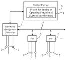
- FIG. 1 is a schematic diagram of one embodiment of a system for testing an operating condition of light emitting diodes (LEDs) on a motherboard;
- LEDs light emitting diodes
- FIG. 2 is a schematic diagram illustrating one embodiment of a signal-flow chart between a baseboard management controller and the system of FIG. 1 ;
- FIG. 3 is a schematic diagram of one embodiment of the system of FIG. 1 comprising software function modules
- FIG. 4 and FIG. 5 are schematic diagrams illustrating one embodiment of a work state, of each of the LEDs, set by a setting module
- FIG. 7 is a flowchart of one embodiment of a method for testing an operating condition of LEDs on a motherboard.
- FIG. 1 is a schematic diagram of one embodiment of a system 1 for testing an operating condition of light emitting diodes (LEDs) on a motherboard (hereinafter, “the system 1 ”).
- the system 1 includes a motherboard, comprising a plurality of LEDs 2 to be tested.
- the motherboard typically includes a baseboard management controller (BMC) 3 , an inter-integrated circuit bus (I 2 C bus) 4 , a plurality of pins 5 , and a storage device 6 .
- the plurality of pins 5 are electrically connected to the BMC 3 via the I 2 C bus 4 ; and the BMC 3 is electrically connected to the storage device 6 via a data bus, such as a data line or a control line.
- the motherboard may be connected with a monitor (not shown) to provide a user interface for displaying test data and a test result to a user.
- some of the LEDs 2 are directly controlled by the BMC 3
- some of the LEDs 2 that are connected to the pins 5 may be indirectly controlled by the BMC 3 via the I 2 C bus 4 .
- the storage device 6 may be a hard disk or other portable storage device.
- the system 1 may be installed in the storage device 6 , and be configured to test operating conditions of each of the LEDs 2 , and be further configured for outputting the test data and the test result to the monitor for display.
- FIG. 2 is a schematic diagram illustrating one embodiment of a signal-flow chart between the BMC 3 and the system 1 of FIG. 1 .
- the BMC 3 communicates with the system 1 via a keyboard controller style (KCS) interface 7 .
- KCS keyboard controller style
- the BMC 3 generates commands which signal the system 1 to control the LEDs 2 to be either in a bright state, a dim state, or a flicker state.
- the BMC 3 may generate commands to signal the system 1 to test operating conditions of the LEDs 2 in the different states and output a test result.
- FIG. 3 is a schematic diagram of one embodiment of the system 1 comprising software function modules.
- the software modules may be used to implement certain functions and will be described in greater detail below.
- the system 1 may comprise an assigning module 100 , a setting module 102 , a controlling module 104 , a determining module 106 , a receiving module 108 , a comparing module 110 , and a reporting module 112 .
- the various modules 100 , 102 , 104 , 106 , 108 , 110 , 112 of the system 1 may be executed by a processor 116 . Accordingly, the system 1 may be run on a computerized device 114 , such as a personal computer.
- a graphical simulation of the motherboard comprising the plurality of LEDs 2 may be displayed on the monitor. In one embodiment, if an LED on a motherboard malfunctions, then an operating condition of the LED may not be acceptable to the system 1 .
- the assigning module 100 is configured for assigning an LED identification for each of the LEDs 2 according to a position of each of the LEDs 2 on the motherboard. In another embodiment, the assigning module 100 may assign a serial number corresponding to each of the LEDs 2 , according to a function of each of the LEDs 2 .
- the setting module 102 is configured for randomly selecting one LED (hereinafter a first LED 2 ) from the plurality of the LEDs 2 , and another LED (hereinafter a second LED 2 ) from the plurality of the LEDs 2 , by randomly selecting two LED identifications (i.e. a first LED identification and a second LED identification respectively).
- the setting module 102 may locate the first LED 2 and the second LED 2 corresponding to the two selected LED identifications and set the first LED 2 to be in a bright state, set the second LED 2 to be in a dim state, and set any remaining LEDs 2 to be in a flicker state.
- a work state for each of the LEDs 2 configured by the setting module 102 will be illustrated.
- the terms, “bright state” and “dark state” may refer to a luminosity, or light intensity, of an LED.
- the term, “light state” may refer to a higher luminosity, or light intensity, of an LED when compared to the term, “dark state.”
- the term, “flicker state” may refer to a turning on and a turning off of an LED for a brief period of time.
- the setting module 102 may set a work state for each of the LEDs 2 . As illustrated in both FIG. 4 and FIG. 5 , each circle represents one of the LEDs 2 .
- the flicker state may comprise a flicker mode and a flicker frequency for the LEDs 2 that are not in the bright state or in the dim state.
- the setting module 102 may set the flicker mode as “bright to dark” or “dark to bright,” and set a flickering time indicating how long to change from “bright to dark” or from “dark to bright” for the LEDs 2 .
- the controlling module 104 is configured to control and operate all the LEDs 2 , and to detect actual work states of the LEDs 2 .
- the determining module 106 is configured for determining a total count of the LEDs 2 that are in the bright state and a total count of the LEDs 2 that are in the dim state according to actual work states of the LEDs 2 .
- the determining module 106 may determine that the LEDs 2 on the motherboard are malfunctioning if the total count of the LEDs 2 in the bright state is more than one or equal to zero, or if the total count of the LEDs 2 in the dim state is more than one or equal to zero. In another embodiment, if the total count of the LEDs 2 in the bright state is equal to one, and the total count of the LEDs 2 in the dim state is also equal to one, then the receiving module 108 is configured for receiving a first LED identification input and a second LED identification input. The receiving module 108 may then display the two LED identification inputs on the monitor. In one embodiment, the first LED identification input should be in the bright state and the second LED identification input should be in the dim state.
- the comparing module 110 is configured for comparing the first LED identification with the first LED identification input, and comparing the second LED identification with the second LED identification input.
- the reporting module 110 is configured for reporting a test result according to the comparison result as noted above, and storing the test result in a storage system.
- the storage system is at least one of a hard disk drive, a compact disc, a digital video disc, or a tape drive.
- the reporting module 110 may output a number identical notification that indicates the LEDs 2 are working normally.
- the reporting module 110 outputs a number different notification that indicates the LEDs 2 are malfunctioning.
- FIG. 6 is a schematic diagram illustrating one embodiment of the LEDs 2 in a normal state as shown in block 600 .
- the setting module 102 may set an LED “a” in the bright state, set an LED “b” in the dim state, set any remaining LEDs 2 in the flicker state, and set the flicker mode, for the remaining LEDs, as “bright to dark.”
- Block 610 and block 620 illustrate one embodiment of actual work states of the LEDs 2 as described above.
- FIG. 7 is a flowchart of one embodiment of a method for testing an operating condition of the LEDs 2 on a motherboard. Depending on the embodiment, additional blocks may be added, others removed, and the ordering of the blocks may be changed.
- the assigning module 100 assigns an LED identification for each of the LEDs 2 according to a position of each of the LEDs 2 on the motherboard.
- the setting module 102 randomly selects a first LED 2 and a second LED 2 , from the plurality of the LEDs 2 , by randomly selecting a corresponding first LED identification and a corresponding second LED identification respectively.
- the setting module 102 may then locate the first LED 2 and the second LED 2 corresponding to the two selected LED identifications, and set the first LED 2 to be in a bright state, set the second LED 2 to be in a dim state, and set any remaining LEDs 2 to be in the flicker state.
- the setting module 102 may also set a flicker mode and a flicker frequency for the remaining LEDs 2 .
- the controlling module 104 controls all the LEDs 2 , and detects an actual work state for each of the LEDs 2 .
- the determining module 106 determines a total count of the LEDs 2 that are in the bright state and determines a total count of the LEDs 2 that are in the dim state. It may be understood that the determining may be according to the actual work state of each of the LEDs 2 . If the total count of LEDs in the bright state and the total count of the LEDs 2 in the dim state are both equal to one, then the flow may move to block 708 . Otherwise, if the total count of the LEDs 2 in the bright state is more than one or equal to zero, or if the total count of the LEDs 2 in the dim state is more than one or equal to zero, (i.e. the LEDs 2 are malfunctioning), then the procedure ends.
- the receiving module 108 receives a first LED identification input and a second LED identification input, and displays the two LED identification inputs on the monitor.
- the first LED identification input corresponding to the LED 2 should be in the bright state and the second LED identification input corresponding to the LED 2 should be in the dim state.
- the comparing module 110 determines if the two LED identification inputs in block S 708 are identical by comparing the first LED identification input with the first LED identification and comparing the second LED identification input with the second LED identification.
- the reporting module 110 outputs a number different notification that indicates the LEDs 2 are malfunctioning as shown in block S 712 , and determines a malfunctioning LED.
- the reporting module 110 outputs a number identical notification that indicates the LEDs 2 are working normally.
- a user may use the setting module 102 to repeatedly select two LED identifications to test the LEDs 2 until all of the LEDs 2 have been tested. For example, after the above blocks, S 700 -S 714 , the user may use the setting module 102 to reselect two LED identifications, and repeat the blocks S 702 -S 710 to test the LEDs 2 again. In one embodiment, both of the two reselected LED identifications may be different from the first LED identification and the second LED identification.
- FIG. 5 illustrates one embodiment of how the LEDs “c” and “d” are different from the LEDs “a” and “b” in FIG. 4 .
- the setting module 102 may randomly select two LEDs 2 to test as illustrated in block S 702 .
Landscapes
- Physics & Mathematics (AREA)
- Optics & Photonics (AREA)
- General Physics & Mathematics (AREA)
- Testing Of Individual Semiconductor Devices (AREA)
- Led Devices (AREA)
Applications Claiming Priority (3)
| Application Number | Priority Date | Filing Date | Title |
|---|---|---|---|
| CN200710202343.6 | 2007-10-31 | ||
| CN200710202343 | 2007-10-31 | ||
| CN2007102023436A CN101424722B (zh) | 2007-10-31 | 2007-10-31 | 主板发光二极管测试系统及方法 |
Publications (2)
| Publication Number | Publication Date |
|---|---|
| US20090108864A1 US20090108864A1 (en) | 2009-04-30 |
| US7714604B2 true US7714604B2 (en) | 2010-05-11 |
Family
ID=40582026
Family Applications (1)
| Application Number | Title | Priority Date | Filing Date |
|---|---|---|---|
| US12/169,638 Expired - Fee Related US7714604B2 (en) | 2007-10-31 | 2008-07-09 | System and method for testing an operating condition of LEDs on a motherboard |
Country Status (2)
| Country | Link |
|---|---|
| US (1) | US7714604B2 (es) |
| CN (1) | CN101424722B (es) |
Cited By (1)
| Publication number | Priority date | Publication date | Assignee | Title |
|---|---|---|---|---|
| US20080112607A1 (en) * | 2006-11-10 | 2008-05-15 | Hon Hai Precision Industry Co., Ltd. | System and method for testing leds on a motherboard |
Families Citing this family (4)
| Publication number | Priority date | Publication date | Assignee | Title |
|---|---|---|---|---|
| CN102194392B (zh) * | 2011-03-25 | 2013-01-09 | 华南理工大学 | 一种led数码管质量检测方法 |
| CN110441713A (zh) * | 2019-07-12 | 2019-11-12 | 苏州浪潮智能科技有限公司 | 一种通过bmc自动测试服务器led灯稳定性的方法 |
| CN116760749B (zh) * | 2023-08-15 | 2023-10-17 | 湖南博匠信息科技有限公司 | 一种通过bmc定位服务器物理位置的方法 |
| CN119147223B (zh) * | 2024-08-21 | 2025-11-21 | 环旭(深圳)电子科创有限公司 | 光源状态检测系统及光源状态检测方法 |
Citations (10)
| Publication number | Priority date | Publication date | Assignee | Title |
|---|---|---|---|---|
| US4808815A (en) * | 1987-03-23 | 1989-02-28 | Genrad, Inc. | Apparatus for testing light-emitting devices using probe means having a preselected pattern arrangement |
| US4843326A (en) * | 1987-08-17 | 1989-06-27 | Smythe Robert H | Electrical testing device for the power input to automobile telephone installations |
| JPH06308183A (ja) * | 1993-04-21 | 1994-11-04 | Sumitomo Wiring Syst Ltd | 発光ダイオードを有する回路基板の導通検査方法と、それに用いる導通検査装置 |
| US6028441A (en) * | 1997-08-14 | 2000-02-22 | Alvord; Robert J. | Self-test routine and circuit for LED display |
| US6075448A (en) | 1998-05-21 | 2000-06-13 | Verkhovskiy; Yan | Apparatus and method for testing an electrical circuit |
| US6490037B1 (en) * | 2000-11-13 | 2002-12-03 | Test Coach Corporation | Method and apparatus for verifying a color of an LED in a printed circuit board |
| US20060267626A1 (en) * | 2005-04-21 | 2006-11-30 | De-Hua Dang | System and method for testing an led and a connector thereof |
| US20080103706A1 (en) * | 2006-10-27 | 2008-05-01 | Hon Hai Precision Industry Co., Ltd. | System and method for testing leds on a motherboard |
| US20080112607A1 (en) * | 2006-11-10 | 2008-05-15 | Hon Hai Precision Industry Co., Ltd. | System and method for testing leds on a motherboard |
| US20090262338A1 (en) * | 2008-04-21 | 2009-10-22 | Hong Fu Jin Precision Industry (Shenzhen) Co., Ltd. | Testing system and testing method for keyboard light of mobile phone |
Family Cites Families (1)
| Publication number | Priority date | Publication date | Assignee | Title |
|---|---|---|---|---|
| CN100516901C (zh) * | 2005-07-27 | 2009-07-22 | 鸿富锦精密工业(深圳)有限公司 | 发光二极管面板测试系统及方法 |
-
2007
- 2007-10-31 CN CN2007102023436A patent/CN101424722B/zh not_active Expired - Fee Related
-
2008
- 2008-07-09 US US12/169,638 patent/US7714604B2/en not_active Expired - Fee Related
Patent Citations (11)
| Publication number | Priority date | Publication date | Assignee | Title |
|---|---|---|---|---|
| US4808815A (en) * | 1987-03-23 | 1989-02-28 | Genrad, Inc. | Apparatus for testing light-emitting devices using probe means having a preselected pattern arrangement |
| US4843326A (en) * | 1987-08-17 | 1989-06-27 | Smythe Robert H | Electrical testing device for the power input to automobile telephone installations |
| JPH06308183A (ja) * | 1993-04-21 | 1994-11-04 | Sumitomo Wiring Syst Ltd | 発光ダイオードを有する回路基板の導通検査方法と、それに用いる導通検査装置 |
| US6028441A (en) * | 1997-08-14 | 2000-02-22 | Alvord; Robert J. | Self-test routine and circuit for LED display |
| US6075448A (en) | 1998-05-21 | 2000-06-13 | Verkhovskiy; Yan | Apparatus and method for testing an electrical circuit |
| US6490037B1 (en) * | 2000-11-13 | 2002-12-03 | Test Coach Corporation | Method and apparatus for verifying a color of an LED in a printed circuit board |
| US20060267626A1 (en) * | 2005-04-21 | 2006-11-30 | De-Hua Dang | System and method for testing an led and a connector thereof |
| US7382148B2 (en) * | 2005-04-21 | 2008-06-03 | Hong Fu Jin Precision Industry (Shen Zhen) Co., Ltd. | System and method for testing an LED and a connector thereof |
| US20080103706A1 (en) * | 2006-10-27 | 2008-05-01 | Hon Hai Precision Industry Co., Ltd. | System and method for testing leds on a motherboard |
| US20080112607A1 (en) * | 2006-11-10 | 2008-05-15 | Hon Hai Precision Industry Co., Ltd. | System and method for testing leds on a motherboard |
| US20090262338A1 (en) * | 2008-04-21 | 2009-10-22 | Hong Fu Jin Precision Industry (Shenzhen) Co., Ltd. | Testing system and testing method for keyboard light of mobile phone |
Cited By (2)
| Publication number | Priority date | Publication date | Assignee | Title |
|---|---|---|---|---|
| US20080112607A1 (en) * | 2006-11-10 | 2008-05-15 | Hon Hai Precision Industry Co., Ltd. | System and method for testing leds on a motherboard |
| US7965884B2 (en) * | 2006-11-10 | 2011-06-21 | Hon Hai Precision Industry Co., Ltd. | System and method for testing LEDs on a motherboard |
Also Published As
| Publication number | Publication date |
|---|---|
| US20090108864A1 (en) | 2009-04-30 |
| CN101424722A (zh) | 2009-05-06 |
| CN101424722B (zh) | 2011-01-05 |
Similar Documents
| Publication | Publication Date | Title |
|---|---|---|
| US8443238B2 (en) | System and method for testing hard disk ports | |
| CN112654119B (zh) | Led驱动测试方法、驱动器、系统及电子设备 | |
| US8432178B2 (en) | Testing device and method thereof | |
| US8538720B2 (en) | Cold boot test system and method for electronic devices | |
| US7714604B2 (en) | System and method for testing an operating condition of LEDs on a motherboard | |
| US7351947B2 (en) | System and method for ambient light sensor testing for an information handling system display | |
| US10440802B1 (en) | Lighting control system and method | |
| CN107589568B (zh) | 一种led灯串自动学习检测装置及方法 | |
| US20080103706A1 (en) | System and method for testing leds on a motherboard | |
| CN111063386A (zh) | Ddr芯片测试方法和装置 | |
| CN105825819B (zh) | 显示模组和显示模组的亮度调节方法 | |
| US20200311013A1 (en) | Hard disk status monitoring system and hard disk status monitoring method | |
| US9188628B2 (en) | Load apparatus for testing | |
| CN102479140A (zh) | 计算机系统及其硬盘状态显示方法 | |
| US8250409B2 (en) | Boot test apparatus and method of computer system | |
| CN104156291B (zh) | 服务器及其检测方法 | |
| US7434071B2 (en) | Multi-state recognition device of server blade system | |
| CN117347905A (zh) | 灯板故障检测方法及装置 | |
| CN108319540B (zh) | 硬盘灯号控制系统 | |
| KR102037069B1 (ko) | 표시 패널의 검사 장치 및 그 방법 | |
| US20140164815A1 (en) | Server analyzing system | |
| CN103902415A (zh) | 硬盘测试系统及方法 | |
| CN112858946A (zh) | 光源测试装置 | |
| CN114217213B (zh) | 一种用于有源led矩阵面板的测试方法 | |
| CN1979443A (zh) | 计算机平台内存状态数据主机端自动显示方法及系统 |
Legal Events
| Date | Code | Title | Description |
|---|---|---|---|
| AS | Assignment |
Owner name: HON HAI PRECISION INDUSTRY CO., LTD., TAIWAN Free format text: ASSIGNMENT OF ASSIGNORS INTEREST;ASSIGNORS:LIU, CHIH-CHIANG;CHEN, WEI-YUAN;REEL/FRAME:021209/0388 Effective date: 20080630 Owner name: HON HAI PRECISION INDUSTRY CO., LTD.,TAIWAN Free format text: ASSIGNMENT OF ASSIGNORS INTEREST;ASSIGNORS:LIU, CHIH-CHIANG;CHEN, WEI-YUAN;REEL/FRAME:021209/0388 Effective date: 20080630 |
|
| FPAY | Fee payment |
Year of fee payment: 4 |
|
| FEPP | Fee payment procedure |
Free format text: MAINTENANCE FEE REMINDER MAILED (ORIGINAL EVENT CODE: REM.) |
|
| LAPS | Lapse for failure to pay maintenance fees |
Free format text: PATENT EXPIRED FOR FAILURE TO PAY MAINTENANCE FEES (ORIGINAL EVENT CODE: EXP.) |
|
| STCH | Information on status: patent discontinuation |
Free format text: PATENT EXPIRED DUE TO NONPAYMENT OF MAINTENANCE FEES UNDER 37 CFR 1.362 |
|
| FP | Lapsed due to failure to pay maintenance fee |
Effective date: 20180511 |