US7713103B2 - Cooling system of an amphibious vehicle - Google Patents
Cooling system of an amphibious vehicle Download PDFInfo
- Publication number
- US7713103B2 US7713103B2 US11/597,216 US59721605A US7713103B2 US 7713103 B2 US7713103 B2 US 7713103B2 US 59721605 A US59721605 A US 59721605A US 7713103 B2 US7713103 B2 US 7713103B2
- Authority
- US
- United States
- Prior art keywords
- cooling system
- vehicle
- duct
- air
- cooling
- Prior art date
- Legal status (The legal status is an assumption and is not a legal conclusion. Google has not performed a legal analysis and makes no representation as to the accuracy of the status listed.)
- Expired - Lifetime
Links
Images




Classifications
-
- B—PERFORMING OPERATIONS; TRANSPORTING
- B60—VEHICLES IN GENERAL
- B60F—VEHICLES FOR USE BOTH ON RAIL AND ON ROAD; VEHICLES CAPABLE OF TRAVELLING IN OR ON DIFFERENT MEDIA, e.g. AMPHIBIOUS VEHICLES
- B60F3/00—Amphibious vehicles, i.e. vehicles capable of travelling both on land and on water; Land vehicles capable of travelling under water
- B60F3/003—Parts or details of the vehicle structure; vehicle arrangements not otherwise provided for
- B60F3/0053—Particular devices for gas circulation, e.g. air admission, cooling, watertightness
-
- F—MECHANICAL ENGINEERING; LIGHTING; HEATING; WEAPONS; BLASTING
- F01—MACHINES OR ENGINES IN GENERAL; ENGINE PLANTS IN GENERAL; STEAM ENGINES
- F01P—COOLING OF MACHINES OR ENGINES IN GENERAL; COOLING OF INTERNAL-COMBUSTION ENGINES
- F01P3/00—Liquid cooling
- F01P3/18—Arrangements or mounting of liquid-to-air heat-exchangers
-
- F—MECHANICAL ENGINEERING; LIGHTING; HEATING; WEAPONS; BLASTING
- F01—MACHINES OR ENGINES IN GENERAL; ENGINE PLANTS IN GENERAL; STEAM ENGINES
- F01P—COOLING OF MACHINES OR ENGINES IN GENERAL; COOLING OF INTERNAL-COMBUSTION ENGINES
- F01P5/00—Pumping cooling-air or liquid coolants
- F01P5/02—Pumping cooling-air; Arrangements of cooling-air pumps, e.g. fans or blowers
-
- F—MECHANICAL ENGINEERING; LIGHTING; HEATING; WEAPONS; BLASTING
- F01—MACHINES OR ENGINES IN GENERAL; ENGINE PLANTS IN GENERAL; STEAM ENGINES
- F01P—COOLING OF MACHINES OR ENGINES IN GENERAL; COOLING OF INTERNAL-COMBUSTION ENGINES
- F01P1/00—Air cooling
-
- F—MECHANICAL ENGINEERING; LIGHTING; HEATING; WEAPONS; BLASTING
- F01—MACHINES OR ENGINES IN GENERAL; ENGINE PLANTS IN GENERAL; STEAM ENGINES
- F01P—COOLING OF MACHINES OR ENGINES IN GENERAL; COOLING OF INTERNAL-COMBUSTION ENGINES
- F01P1/00—Air cooling
- F01P2001/005—Cooling engine rooms
-
- F—MECHANICAL ENGINEERING; LIGHTING; HEATING; WEAPONS; BLASTING
- F01—MACHINES OR ENGINES IN GENERAL; ENGINE PLANTS IN GENERAL; STEAM ENGINES
- F01P—COOLING OF MACHINES OR ENGINES IN GENERAL; COOLING OF INTERNAL-COMBUSTION ENGINES
- F01P2050/00—Applications
- F01P2050/02—Marine engines
- F01P2050/08—Engine room
Definitions
- the present invention relates to a cooling system for cooling components of an amphibious vehicle.
- Amphibious vehicles have unique requirements for cooling of components as a result of the body of the vehicle being in the form of a hull for use of the vehicle on water.
- the body cannot be provided with openings on the underneath or sides to permit the flow of air for cooling, as are used on road going vehicles, as these openings will permit the ingress of water into the hull.
- Cooling of vehicle components such as transmission components, e.g. drive shafts, gearboxes and brakes, a prime mover, e.g. an internal combustion engine, and electronic components, e.g. an engine management electronic control unit must therefore be achieved using alternative means.
- transmission components e.g. drive shafts, gearboxes and brakes
- prime mover e.g. an internal combustion engine
- electronic components e.g. an engine management electronic control unit
- amphibious vehicle cooling systems are known in the art, most are concerned with providing adequate cooling for an internal combustion engine. These cooling systems take the form of a traditional radiator used to cool a liquid coolant which is circulated around/within an internal combustion engine.
- Such systems require complex plumbing arrangements, often passing through structural bulkheads, and are not easily adaptable to cool multiple heat generating sources. Accordingly, there exists a need to improve on known amphibious cooling systems.
- a cooling system of an amphibious vehicle having at least one retractable wheel assembly comprising:
- At the first proximal end at least one air inlet to induct cooling air into the at least one duct, wherein the at least one air inlet is oriented such that forward movement of the vehicle forces air through the inlet;
- At the second distal end at least one air outlet to exhaust the cooling air from the at least one duct;
- the at least one duct having, between an air inlet and an air outlet, at least one component of the vehicle requiring cooling
- the at least one duct having, between an air inlet and an air outlet, means to positively draw air through the at least one duct.
- the present invention has particular utility in an amphibious vehicle having at least one mid- or rear-mounted engine or other prime mover.
- the air duct supplies a flow of air to the mid and/or rear of the vehicle to cool the engine and the engine bay.
- the air duct may contain other components to be cooled or additional ducts may be provided to supply cooling air to other components of the vehicle, for example a differential or a gearbox.
- the or each air duct runs substantially along the centre line of the vehicle.
- the walls of an air duct are separate from the walls of the hull of the vehicle.
- At least one wall of an air duct is at least in part formed by the hull of the vehicle.
- the air flow passing through the duct may be cooled by coming into contact with the hull of the vehicle.
- the hull of the vehicle, or at least a portion thereof, is a good thermal conductor.
- the amphibious vehicle has a triple vee hull.
- the triple vee hull is a cathedral hull as described in the Applicant's co-pending UK patent application no. 0411546.5 entitled ‘An Amphibious Vehicle’.
- one or more of the air ducts are formed at least in part by one or more of the vees of the hull.
- the amphibious vehicle may be a monohull or have a catamaran hull.
- the means to draw air through the one or more ducts is a fan.
- the fan may be driven by any suitable means, for example, it may be attached to the crankshaft of an internal combustion engine or it may be driven by an electric or hydraulic motor.
- the one or more air ducts pass through one or more bulkheads of the vehicle.
- the flow of air through the one or more air ducts may be from front to rear or from rear to front.
- a method of cooling at least one component of an amphibious vehicle having at least one retractable wheel assembly comprising the steps of:
- a third aspect of the present invention there is provided a method for providing a flow of air through an amphibious vehicle having at least one retractable wheel assembly, the method comprising the steps of:
- a rear or mid-mounted engine is preferred for appropriate weight distribution.
- FIG. 1 is a schematic longitudinal cross-sectional view through a cooling system of an amphibious vehicle according to a first preferred embodiment of the present invention, taken along line C-C of FIG. 2 ;
- FIG. 2 is a schematic transverse cross-sectional view through the cooling system of the amphibious vehicle of FIG. 1 , taken along line B-B;
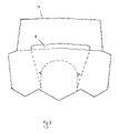
- FIG. 3 is a schematic transverse cross-sectional view through the cooling system of the amphibious vehicle of FIG. 1 , taken along line A-A;
- FIG. 4 is a schematic front elevation view of the cooling system and amphibious vehicle of FIG. 1 ;
- FIG. 5 is a schematic plan view of the cooling system and amphibious vehicle of FIG. 1 ;
- FIG. 6 is a schematic front elevation view of a cooling system and amphibious vehicle according to a second embodiment of the present invention.
- FIG. 1 A cooling system 1 of an amphibious vehicle 3 according to a first preferred embodiment of the present invention is shown in FIG. 1 .
- An air inlet 5 At the front of the vehicle 3 is an air inlet 5 .
- An air outlet 7 At the rear of the vehicle 3 is an air inlet 5 .
- the air inlet 5 is a slot provided transversely and centrally across the vehicle 3 , as shown in FIG. 4 .
- the air outlet 7 is a centrally located opening in the stern.
- a duct 9 extends along the centre line of the vehicle 3 , in the central vee 10 ( FIG. 2 ) of the cathedral hull, the duct 9 extending between the air inlet 5 and the air outlet 7 .
- the duct 9 passes through a front bulkhead 11 and a rear bulkhead 13 of a passenger compartment 15 .
- the cross-sectional profile of the duct 9 changes from a shallow rectangle at the air inlet 5 to a deeper rectangle as the duct 9 passes through the front bulkhead 11 , as shown in FIG. 3 .
- Vehicle components may be contained within the duct 9 at any point along its length, as shown in FIG. 1 .
- the duct 9 enters the engine bay 17 which contains the engine 19 and other components, for example transmission components.
- a fan 21 is provided to the rear of the engine bay 17 , adjacent to the air outlet 7 , and is arranged so as to be of substantially vertical orientation.
- Air flow through the duct 9 is achieved by air being forced through the air inlet 5 by virtue of forward movement of the vehicle 3 (so-called ram effect) and/or as a result of a negative pressure created in the duct 9 by operation of the fan 21 .
- the air drawn through the duct 9 by the fan 21 is sufficient to cool the components of the vehicle 3 when it is stationary and the engine is at an idle, as the heat generated by the components is at a minimum.
- the combination of the forcing of air through the air inlet 5 (ram air) and the drawing of air through the duct 9 results in a greater flow of air as required for sufficient cooling.
- a separate, dedicated liquid cooling system is attached to the engine 19 .
- This optional liquid cooling system is provided in addition to the cooling system according to the present invention.
- a radiator 23 is located at the front of the vehicle 3 in a separate compartment 25 .
- the compartment 25 is provided with an air inlet 27 through which air is forced (ram effect) by forward movement of the vehicle.
- fans 29 are provided to draw air through the radiator 23 to provide additional cooling when the engine coolant temperature exceeds a preset threshold temperature.
- the air that passes through the radiator 23 is exhausted through the air outlet 31 .
- the air exhausted via air outlet 31 may be ducted away to the side of the vehicle or otherwise (entirely or to one degree or other) such that it is not inducted by the air inlet 5 .
- the air outlet takes the form of two air outlets 31 provided one on either side of the vehicle 3 .
- the radiator 23 is oriented substantially horizontally to protect the radiator fins from being damaged by water forced through the air inlet 27 .
- the pipes of the liquid cooling system may be contained at least in part within the duct 9 or may be routed adjacent thereto so that the temperature of the coolant liquid flowing through these can be reduced on both the radiator inlet and outlet legs. Furthermore, accommodating the pipes within the duct 9 avoids the need to route such pipes directly through bulkheads of the vehicle 3 .
- the flow of air through the duct 9 can be used to ensure that there is not a build up of potentially explosive fumes, for example petrol fumes, in the engine bay 17 of the vehicle 3 .
- the flow of air may also be used to purge petrol fumes vented from a petrol tank. As such, the present invention provides additional ventilation for the vehicle.
- FIG. 6 schematically illustrates a front elevation view of a monohull amphibious vehicle provided with the cooling system according to the present invention.
- the duct 9 may take any suitable form.
- the exact form adopted is dependent, inter alia, upon the hull type, the number of components to be cooled and their location within the vehicle, and packaging constraints.
- a plurality of ducts may be provided rather than just one. Consequently, the number of air inlets and air outlets is variable.
- the or each duct may have branches and any such branches may remain separate or recombine into or to form one or more ducts.
- the ducts may be of tortuous or labyrinthine form.
- the cross sectional area or form of the or each duct may be variable and/or different to one another.
- each wheel assembly (including wheel 6 , FIGS. 4 and 6 ) is retractable above the waterline and that the vehicle can plane on water.
- a rear or mid-mounted engine is preferred for appropriate weight distribution. It is especially preferred that the engine is located in the rear two thirds of the length of the vehicle, and more preferably the rear half of the vehicle. Consequently, it is preferred that at least one of the one or more ducts extends along at least one third of the length of the vehicle, more preferably at least half of the length of the vehicle.
Landscapes
- Engineering & Computer Science (AREA)
- Chemical & Material Sciences (AREA)
- Combustion & Propulsion (AREA)
- Mechanical Engineering (AREA)
- General Engineering & Computer Science (AREA)
- Transportation (AREA)
- Cooling, Air Intake And Gas Exhaust, And Fuel Tank Arrangements In Propulsion Units (AREA)
Applications Claiming Priority (3)
| Application Number | Priority Date | Filing Date | Title |
|---|---|---|---|
| GB0411548A GB2414440A (en) | 2004-05-24 | 2004-05-24 | A cooling apparatus for an amphibious vehicle |
| GB0411548.1 | 2004-05-24 | ||
| PCT/GB2005/002052 WO2005115774A2 (en) | 2004-05-24 | 2005-05-24 | A cooling system of an amphibious vehicle |
Publications (2)
| Publication Number | Publication Date |
|---|---|
| US20080032572A1 US20080032572A1 (en) | 2008-02-07 |
| US7713103B2 true US7713103B2 (en) | 2010-05-11 |
Family
ID=32607864
Family Applications (1)
| Application Number | Title | Priority Date | Filing Date |
|---|---|---|---|
| US11/597,216 Expired - Lifetime US7713103B2 (en) | 2004-05-24 | 2005-05-24 | Cooling system of an amphibious vehicle |
Country Status (5)
| Country | Link |
|---|---|
| US (1) | US7713103B2 (de) |
| EP (1) | EP1765613A2 (de) |
| CN (2) | CN1997528A (de) |
| GB (1) | GB2414440A (de) |
| WO (1) | WO2005115774A2 (de) |
Cited By (4)
| Publication number | Priority date | Publication date | Assignee | Title |
|---|---|---|---|---|
| US20120100792A1 (en) * | 2010-10-22 | 2012-04-26 | Tata Technologies Pte Limited | Cost effective and efficient air circulation system for a vehicle having rotomolded body assembly |
| US20120137945A1 (en) * | 2009-06-03 | 2012-06-07 | Austal Ships Pty Ltd. | Trimaran vehicle deck arrangement |
| US20150129336A1 (en) * | 2013-11-13 | 2015-05-14 | Röchling Automotive SE & Co. KG | Gas-guiding device, in particular air-guiding device, integrated in a motor vehicle beam |
| US20170082092A1 (en) * | 2015-09-23 | 2017-03-23 | Toyota Motor Engineering & Manufacturing North America, Inc. | Wind turbine systems and air channels in vehicles for enhancing energy generation, cooling, and aerodynamics |
Families Citing this family (7)
| Publication number | Priority date | Publication date | Assignee | Title |
|---|---|---|---|---|
| US9107765B2 (en) | 2010-05-07 | 2015-08-18 | Difusion Technologies, Inc. | Medical implants with increased hydrophilicity |
| JP6036169B2 (ja) * | 2012-10-30 | 2016-11-30 | いすゞ自動車株式会社 | 車両の冷却システム |
| US9581071B2 (en) * | 2014-09-25 | 2017-02-28 | Hyster-Yale Group, Inc. | Cooling system for industrial vehicle |
| US10197149B2 (en) * | 2016-03-23 | 2019-02-05 | Kawasaki Jukogyo Kabushiki Kaisha | V-belt type continuously variable transmission |
| ES2645503B2 (es) * | 2016-06-03 | 2018-06-08 | Navantia S.A. | Sistema de refrigeración para lancha de desembarco |
| WO2018056942A2 (en) | 2016-07-28 | 2018-03-29 | Fnss Savunma Si̇stemleri̇ Anoni̇m Şi̇rketi̇ | Cooling unit located independently of the engine partition in military vehicles |
| CN108791735A (zh) * | 2018-07-27 | 2018-11-13 | 苏州飞驰环保科技股份有限公司 | 清漂船主机及液压系统上用的水冷风冷复合冷却系统 |
Citations (28)
| Publication number | Priority date | Publication date | Assignee | Title |
|---|---|---|---|---|
| US1174216A (en) | 1914-03-27 | 1916-03-07 | Clyde Wilkerson | Motor-vehicle. |
| US1816161A (en) * | 1927-07-20 | 1931-07-28 | Joseph B Strauss | Internal combustion engine |
| US1925415A (en) * | 1929-06-03 | 1933-09-05 | Joseph B Strauss | Cooling system for moving vehicles |
| US1934385A (en) * | 1928-06-18 | 1933-11-07 | Joseph B Strauss | Vehicle |
| US2341165A (en) | 1942-12-09 | 1944-02-08 | Gen Motors Corp | Cooling system |
| US2397791A (en) | 1943-01-08 | 1946-04-02 | Ford Motor Co | Amphibious vehicle |
| US2397792A (en) | 1943-08-11 | 1946-04-02 | Ford Motor Co | Cooling system for marine vehicles |
| US2993462A (en) * | 1959-06-25 | 1961-07-25 | Park E Gough | Jet tunnel boat |
| US3114347A (en) | 1960-01-21 | 1963-12-17 | Amphicar Corp Of America | Amphibious vehicle |
| US3266591A (en) * | 1963-07-17 | 1966-08-16 | Kaiser Jeep Corp | Military vehicle |
| US3435798A (en) * | 1967-05-19 | 1969-04-01 | Ltv Aerospace Corp | Low-silhouette vehicle |
| US3446175A (en) * | 1967-07-26 | 1969-05-27 | Aerophysics Co | Marginal terrain vehicle |
| DE1530911A1 (de) | 1965-01-09 | 1969-07-17 | Kloeckner Humboldt Deutz Ag | Amphibienfahrzeug |
| US3903831A (en) | 1973-05-14 | 1975-09-09 | Waterland Corp | Amphibious vehicle |
| DE3226827A1 (de) | 1982-07-17 | 1984-01-19 | Hanns 7590 Achern Trippel | Antrieb fuer schwimmfaehige fahrzeuge, insbesondere amphibienfahrzeuge |
| GB2134857A (en) | 1983-02-11 | 1984-08-22 | Stanley Gordon Rex Simpson | Improvements in or relating to watercraft |
| EP0492655A1 (de) | 1990-12-17 | 1992-07-01 | Isuzu Motors Limited | Amphibisches Kraftfahrzeug |
| SU1752584A1 (ru) | 1989-07-31 | 1992-08-07 | Центральный научно-исследовательский автомобильный и автомоторный институт "НАМИ" | Амфиби |
| US5181478A (en) * | 1991-12-23 | 1993-01-26 | Sebastiano Berardi | Amphibious vehicle with retractable wheels |
| JPH0524420A (ja) * | 1991-07-19 | 1993-02-02 | Isuzu Motors Ltd | 水陸両用車両の操舵装置 |
| US5490572A (en) * | 1991-12-04 | 1996-02-13 | Honda Giken Kogyo Kabushiki Kaisha | Battery temperature control system in electric automobile |
| US5690046A (en) | 1995-11-21 | 1997-11-25 | Grzech, Jr.; Albert S. | Amphibious vehicles |
| US5868093A (en) | 1997-03-11 | 1999-02-09 | Tseng; An-Ping | Amphibious vehicle |
| EP0937959A1 (de) | 1998-02-21 | 1999-08-25 | VXO Group International AG | Amphibien-Panzerfahrzeug |
| US6305333B1 (en) | 1998-02-25 | 2001-10-23 | Komatsu Ltd. | Air blower apparatus |
| US6482052B1 (en) * | 2001-08-21 | 2002-11-19 | John J Giljam | Amphibious vehicle |
| US6786291B1 (en) * | 1999-09-29 | 2004-09-07 | Scania Cv Ab (Publ) | Motor vehicle with a front-mounted engine and air guide chassis |
| US20050272324A1 (en) * | 2002-05-03 | 2005-12-08 | Gibbs Alan T | Amphibious vehicle cooling systems |
Family Cites Families (3)
| Publication number | Priority date | Publication date | Assignee | Title |
|---|---|---|---|---|
| JPH04321411A (ja) * | 1991-04-19 | 1992-11-11 | Isuzu Motors Ltd | 水陸両用車 |
| JP4208341B2 (ja) * | 1999-04-28 | 2009-01-14 | 本田技研工業株式会社 | 車両に搭載された強制空冷式内燃機関のシュラウド |
| US6666735B2 (en) * | 2002-04-11 | 2003-12-23 | Dion Benoit | Jet drive assist for off-road vehicle with flotation |
-
2004
- 2004-05-24 GB GB0411548A patent/GB2414440A/en not_active Withdrawn
-
2005
- 2005-05-24 CN CNA2005800233551A patent/CN1997528A/zh active Pending
- 2005-05-24 US US11/597,216 patent/US7713103B2/en not_active Expired - Lifetime
- 2005-05-24 WO PCT/GB2005/002052 patent/WO2005115774A2/en not_active Ceased
- 2005-05-24 EP EP05746364A patent/EP1765613A2/de not_active Withdrawn
- 2005-05-24 CN CN201510130576.4A patent/CN104875564A/zh active Pending
Patent Citations (29)
| Publication number | Priority date | Publication date | Assignee | Title |
|---|---|---|---|---|
| US1174216A (en) | 1914-03-27 | 1916-03-07 | Clyde Wilkerson | Motor-vehicle. |
| US1816161A (en) * | 1927-07-20 | 1931-07-28 | Joseph B Strauss | Internal combustion engine |
| US1934385A (en) * | 1928-06-18 | 1933-11-07 | Joseph B Strauss | Vehicle |
| US1925415A (en) * | 1929-06-03 | 1933-09-05 | Joseph B Strauss | Cooling system for moving vehicles |
| US2341165A (en) | 1942-12-09 | 1944-02-08 | Gen Motors Corp | Cooling system |
| US2397791A (en) | 1943-01-08 | 1946-04-02 | Ford Motor Co | Amphibious vehicle |
| US2397792A (en) | 1943-08-11 | 1946-04-02 | Ford Motor Co | Cooling system for marine vehicles |
| US2993462A (en) * | 1959-06-25 | 1961-07-25 | Park E Gough | Jet tunnel boat |
| US3114347A (en) | 1960-01-21 | 1963-12-17 | Amphicar Corp Of America | Amphibious vehicle |
| US3266591A (en) * | 1963-07-17 | 1966-08-16 | Kaiser Jeep Corp | Military vehicle |
| DE1530911A1 (de) | 1965-01-09 | 1969-07-17 | Kloeckner Humboldt Deutz Ag | Amphibienfahrzeug |
| US3435798A (en) * | 1967-05-19 | 1969-04-01 | Ltv Aerospace Corp | Low-silhouette vehicle |
| US3446175A (en) * | 1967-07-26 | 1969-05-27 | Aerophysics Co | Marginal terrain vehicle |
| US3903831A (en) | 1973-05-14 | 1975-09-09 | Waterland Corp | Amphibious vehicle |
| DE3226827A1 (de) | 1982-07-17 | 1984-01-19 | Hanns 7590 Achern Trippel | Antrieb fuer schwimmfaehige fahrzeuge, insbesondere amphibienfahrzeuge |
| GB2134857A (en) | 1983-02-11 | 1984-08-22 | Stanley Gordon Rex Simpson | Improvements in or relating to watercraft |
| SU1752584A1 (ru) | 1989-07-31 | 1992-08-07 | Центральный научно-исследовательский автомобильный и автомоторный институт "НАМИ" | Амфиби |
| EP0492655A1 (de) | 1990-12-17 | 1992-07-01 | Isuzu Motors Limited | Amphibisches Kraftfahrzeug |
| US5417177A (en) * | 1990-12-17 | 1995-05-23 | Isuzu Motors, Limited | Amphibian motor vehicle |
| JPH0524420A (ja) * | 1991-07-19 | 1993-02-02 | Isuzu Motors Ltd | 水陸両用車両の操舵装置 |
| US5490572A (en) * | 1991-12-04 | 1996-02-13 | Honda Giken Kogyo Kabushiki Kaisha | Battery temperature control system in electric automobile |
| US5181478A (en) * | 1991-12-23 | 1993-01-26 | Sebastiano Berardi | Amphibious vehicle with retractable wheels |
| US5690046A (en) | 1995-11-21 | 1997-11-25 | Grzech, Jr.; Albert S. | Amphibious vehicles |
| US5868093A (en) | 1997-03-11 | 1999-02-09 | Tseng; An-Ping | Amphibious vehicle |
| EP0937959A1 (de) | 1998-02-21 | 1999-08-25 | VXO Group International AG | Amphibien-Panzerfahrzeug |
| US6305333B1 (en) | 1998-02-25 | 2001-10-23 | Komatsu Ltd. | Air blower apparatus |
| US6786291B1 (en) * | 1999-09-29 | 2004-09-07 | Scania Cv Ab (Publ) | Motor vehicle with a front-mounted engine and air guide chassis |
| US6482052B1 (en) * | 2001-08-21 | 2002-11-19 | John J Giljam | Amphibious vehicle |
| US20050272324A1 (en) * | 2002-05-03 | 2005-12-08 | Gibbs Alan T | Amphibious vehicle cooling systems |
Cited By (8)
| Publication number | Priority date | Publication date | Assignee | Title |
|---|---|---|---|---|
| US20120137945A1 (en) * | 2009-06-03 | 2012-06-07 | Austal Ships Pty Ltd. | Trimaran vehicle deck arrangement |
| US8707881B2 (en) * | 2009-06-03 | 2014-04-29 | Austal Ship Pty Ltd. | Trimaran vehicle deck arrangement |
| US20120100792A1 (en) * | 2010-10-22 | 2012-04-26 | Tata Technologies Pte Limited | Cost effective and efficient air circulation system for a vehicle having rotomolded body assembly |
| US9370882B2 (en) * | 2010-10-22 | 2016-06-21 | Tata Technologies Pte Limited | Cost effective and efficient air circulation system for a vehicle having rotomolded body assembly |
| US20150129336A1 (en) * | 2013-11-13 | 2015-05-14 | Röchling Automotive SE & Co. KG | Gas-guiding device, in particular air-guiding device, integrated in a motor vehicle beam |
| US9623824B2 (en) * | 2013-11-13 | 2017-04-18 | Röchling Automative SE & CO. KG | Gas-guiding device, in particular air-guiding device, integrated in a motor vehicle beam |
| US20170082092A1 (en) * | 2015-09-23 | 2017-03-23 | Toyota Motor Engineering & Manufacturing North America, Inc. | Wind turbine systems and air channels in vehicles for enhancing energy generation, cooling, and aerodynamics |
| US9863403B2 (en) * | 2015-09-23 | 2018-01-09 | Toyota Motor Engineering & Manufacturing North America, Inc. | Wind turbine systems and air channels in vehicles for enhancing energy generation, cooling, and aerodynamics |
Also Published As
| Publication number | Publication date |
|---|---|
| CN1997528A (zh) | 2007-07-11 |
| GB0411548D0 (en) | 2004-06-23 |
| US20080032572A1 (en) | 2008-02-07 |
| WO2005115774A2 (en) | 2005-12-08 |
| WO2005115774A3 (en) | 2007-01-25 |
| CN104875564A (zh) | 2015-09-02 |
| EP1765613A2 (de) | 2007-03-28 |
| GB2414440A (en) | 2005-11-30 |
Similar Documents
| Publication | Publication Date | Title |
|---|---|---|
| CN102421620B (zh) | 冷却风导入结构 | |
| US8955628B2 (en) | Cooling arrangements for vehicles | |
| AU2007313695B2 (en) | Air management system for truck | |
| EP2572918B1 (de) | Einlassstruktur für kühlende luft | |
| EP1501692B1 (de) | Kühlsysteme für ein amphibienfahrzeug | |
| US7713103B2 (en) | Cooling system of an amphibious vehicle | |
| US4966408A (en) | Motor vehicle | |
| EP3471985B1 (de) | Raupengeländefahrzeug | |
| CN1287999C (zh) | 车辆冷却排布 | |
| US12515776B2 (en) | Marine drive unit comprising a closed cooling circuit | |
| US6863582B1 (en) | Air ventilation system for a watercraft | |
| AU2012238213A1 (en) | Air Management System for Truck |
Legal Events
| Date | Code | Title | Description |
|---|---|---|---|
| AS | Assignment |
Owner name: GIBBS TECHNOLOGIES LTD, UNITED KINGDOM Free format text: ASSIGNMENT OF ASSIGNORS INTEREST;ASSIGNOR:BURGOYNE, JEREMY MALCOLM;REEL/FRAME:019716/0926 Effective date: 20070814 Owner name: GIBBS TECHNOLOGIES LTD,UNITED KINGDOM Free format text: ASSIGNMENT OF ASSIGNORS INTEREST;ASSIGNOR:BURGOYNE, JEREMY MALCOLM;REEL/FRAME:019716/0926 Effective date: 20070814 |
|
| STCF | Information on status: patent grant |
Free format text: PATENTED CASE |
|
| FPAY | Fee payment |
Year of fee payment: 4 |
|
| FEPP | Fee payment procedure |
Free format text: ENTITY STATUS SET TO UNDISCOUNTED (ORIGINAL EVENT CODE: BIG.) |
|
| MAFP | Maintenance fee payment |
Free format text: PAYMENT OF MAINTENANCE FEE, 8TH YEAR, LARGE ENTITY (ORIGINAL EVENT CODE: M1552) Year of fee payment: 8 |
|
| MAFP | Maintenance fee payment |
Free format text: PAYMENT OF MAINTENANCE FEE, 12TH YEAR, LARGE ENTITY (ORIGINAL EVENT CODE: M1553); ENTITY STATUS OF PATENT OWNER: LARGE ENTITY Year of fee payment: 12 |