US7669494B2 - Gear box with two pinion shafts - Google Patents
Gear box with two pinion shafts Download PDFInfo
- Publication number
- US7669494B2 US7669494B2 US10/570,815 US57081506A US7669494B2 US 7669494 B2 US7669494 B2 US 7669494B2 US 57081506 A US57081506 A US 57081506A US 7669494 B2 US7669494 B2 US 7669494B2
- Authority
- US
- United States
- Prior art keywords
- gear wheel
- shaft
- counter
- radially
- drive output
- Prior art date
- Legal status (The legal status is an assumption and is not a legal conclusion. Google has not performed a legal analysis and makes no representation as to the accuracy of the status listed.)
- Expired - Fee Related, expires
Links
Images

Classifications
-
- F—MECHANICAL ENGINEERING; LIGHTING; HEATING; WEAPONS; BLASTING
- F16—ENGINEERING ELEMENTS AND UNITS; GENERAL MEASURES FOR PRODUCING AND MAINTAINING EFFECTIVE FUNCTIONING OF MACHINES OR INSTALLATIONS; THERMAL INSULATION IN GENERAL
- F16H—GEARING
- F16H57/00—General details of gearing
- F16H57/02—Gearboxes; Mounting gearing therein
- F16H57/02004—Gearboxes; Mounting gearing therein the gears being positioned relative to one another by rolling members or by specially adapted surfaces on the gears, e.g. by a rolling surface with the diameter of the pitch circle
-
- F—MECHANICAL ENGINEERING; LIGHTING; HEATING; WEAPONS; BLASTING
- F16—ENGINEERING ELEMENTS AND UNITS; GENERAL MEASURES FOR PRODUCING AND MAINTAINING EFFECTIVE FUNCTIONING OF MACHINES OR INSTALLATIONS; THERMAL INSULATION IN GENERAL
- F16H—GEARING
- F16H37/00—Combinations of mechanical gearings, not provided for in groups F16H1/00 - F16H35/00
- F16H37/02—Combinations of mechanical gearings, not provided for in groups F16H1/00 - F16H35/00 comprising essentially only toothed or friction gearings
- F16H37/04—Combinations of toothed gearings only
- F16H37/042—Combinations of toothed gearings only change gear transmissions in group arrangement
- F16H37/043—Combinations of toothed gearings only change gear transmissions in group arrangement without gears having orbital motion
-
- Y—GENERAL TAGGING OF NEW TECHNOLOGICAL DEVELOPMENTS; GENERAL TAGGING OF CROSS-SECTIONAL TECHNOLOGIES SPANNING OVER SEVERAL SECTIONS OF THE IPC; TECHNICAL SUBJECTS COVERED BY FORMER USPC CROSS-REFERENCE ART COLLECTIONS [XRACs] AND DIGESTS
- Y10—TECHNICAL SUBJECTS COVERED BY FORMER USPC
- Y10T—TECHNICAL SUBJECTS COVERED BY FORMER US CLASSIFICATION
- Y10T74/00—Machine element or mechanism
- Y10T74/19—Gearing
- Y10T74/19219—Interchangeably locked
- Y10T74/19233—Plurality of counter shafts
Definitions
- the invention concerns a gearbox with two countershafts for power distribution.
- Modern, powerful vehicle gearboxes usually comprise a main transmission group with a multi-stage basic gear and an upstream or downstream splitter group and/or a downstream range gear group.
- a gearbox housing they mainly comprise an input shaft as a first shaft and a central or main shaft as a second shaft, which can also be the output shaft, as well as one or more countershafts.
- the input and main shafts are essentially concentric with one another.
- gearboxes can be designed with helical gearing, at least for the forward driving range.
- the axial forces from the helical gearing have to be taken up by an axial bearing and transmitted to the housing.
- Gearboxes with the structure described can have one or more countershafts.
- the main transmission group comprises two shafts arranged essentially one behind the other, one of which, namely either the input shaft or the main shaft of the main transmission, is mounted radially and axially fixed, while the respective other shaft is mounted floating laterally, i.e., able to move radially to allow the necessary load equalization. In this, care should be taken that an easy swivelling motion of the floating shaft is possible.
- the load equalization can preferably be designed such that the input shaft is mounted fixed on the housing, the countershafts are fixed on the housing and the main shaft is mounted floating in the gear wheels involved in the force flow.
- the known variable-speed gearboxes for goods vehicles have a three- or four-speed main or basic transmission section and an upstream or downstream splitter transmission as an auxiliary transmission, which doubles the number of gear speeds of the main transmission since it splits the transmission ratio steps of the main transmission.
- a range-change transmission downstream from the main transmission extends the ratio range of the main transmission.
- the range-change transmission can be in the form of a planetary gearset or in the form of an arrangement of spur gear wheels.
- a range-change transmission with spur gear wheels downstream from a main transmission with two countershafts for power distribution is known.
- the range-change transmission has two countershafts which are rotationally independent of the countershafts of the main transmission.
- a floating gear wheel is arranged on the main shaft of the gearbox, which meshes with a gear wheel on each of the countershafts of the range-change transmission. This gearbox does not have sufficient capacity for absorbing axial forces that result from the gearing.
- the purpose of the present invention is to improve the axial mounting in a gearbox with two countershafts for power distribution.
- the gear wheel arranged on the main shaft which meshes with gear wheels on the countershafts of the range-change transmission, reaches very high rotation speeds in the disengaged condition in the fast shift position of the range-change transmission.
- the invention proposes a variable-speed gearbox with a main transmission arranged in a housing and a downstream range-change transmission, in which the range-change transmission comprises power distribution to two countershafts and in which a gear wheel is arranged in a radially displaceable manner on a main shaft of the main transmission.
- Pressure combs are provided by way of a gear wheel on the main shaft which meshes with the first gear wheels of the countershaft is maintained in its axial position relative to the drive output shaft. More preferably, the countershafts are maintained in their axial position relative to the drive output shaft by way of pressure combs.
- the gearwheel on the drive output shaft comprises pressure combs which are in contact with pressure combs formed on the second gear wheels of the countershafts in order to take up axial forces.
- the gear wheel on the main shaft has pressure combs which are in contact with pressure combs formed on the first gear wheels of the countershafts in order to take up axial forces.
- the drive output shaft held radially and axially in the housing by a double conical-roller bearing arrangement.
- the countershafts have only one radial mounting in the housing, which preferably comprises roller bearings.
- the countershafts and the gear wheel on the main shaft are guided and maintained axially with the help of the pressure combs.
- the lubrication of the pressure combs can take place from outside and is simple and effective.
- no axial gear forces have to be taken up by the bearings and transferred to the housing.
- the axial mounting of the countershafts can be omitted and the countershafts need only be held in radial-mounting roller bearings.
- the entire gearset combination of the range-change transmission is fixed axially by the mounting of the drive output shaft.
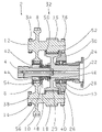
- FIG. 1 is a diagrammatic gearbox with two pinion shafts.
- a main transmission 2 comprises a main shaft 4 , at the end of which is arranged a gear wheel 6 with some radial play.
- the radial mounting of the gear wheel 6 is provided with its outer teeth engaging only in the outer teeth of two first gear wheels 8 and 10 .
- the first gear wheels 8 and 10 are fixedly arranged on respective countershafts 12 and 14 or formed as one piece with the countershafts.
- Each countershaft 12 , 14 has a respective second gearwheel 16 and 18 , in each case again fixed on its countershaft 12 and 14 or made as one piece with the countershafts 12 , 14 .
- the two second gear wheels 16 and 18 mesh with the outer teeth on a gear wheel 20 arranged fixed on a drive output shaft 22 of the variable-speed gearbox or made as one piece therewith.
- a drive output flange 24 is attached to the drive output shaft 22 by which the variable-speed gearbox is connected to further elements of a vehicle drive train (not illustrated here).
- the drive output shaft 22 is mounted by two conical-roller bearings 26 and 28 in a housing 30 of the variable-speed gearbox or of a range-change transmission 32 downstream from the main transmission 2 . Also mounted in the housing 30 are the two countershafts 12 and 14 , each in two roller bearings 34 , 36 and 38 , 40 respectively. These roller bearings 34 , 36 , 38 , 40 only take up radial forces and transfer them to the housing 30 . All the gear teeth of the gear wheels 8 , 10 , 16 , 18 , 20 are of the helical-tooth type from which axial forces result for the absorption and transfer of which the roller bearings 34 , 36 , 38 , 40 are not suitable.
- a gearshift sleeve 42 is arranged at the end of the main shaft 4 is which, by virtue of inner teeth, is connected with the main shaft 4 rotationally fixed but able to be displaced axially.
- the gearshift sleeve 42 can be moved axially.
- the gearshift sleeve 42 with its outer teeth 48 connects the main shaft 4 either with inner teeth 44 on the gear wheel 6 on the main shaft 4 or with inner teeth 46 of the drive output shaft 22 to form a direct connection between the main shaft 4 and the drive output shaft 22 .
- the gearshift sleeve 42 can also adopt a neutral shift position in which there is no connection with either of the inner teeth sets 44 , 46 .
- the drive output shaft 22 is mounted axially fixed in the housing 30 by means of the conical-roller bearings 26 and 28 . Laterally on the outer teeth of the gear wheel 20 on the drive output shaft 22 respective pressure combs 50 and 52 are arranged. The pressure surfaces on the pressure combs 50 and 52 react with correspondingly formed pressure surfaces on the gear wheels 16 and 18 , thereby fixing the countershafts 12 and 14 in the axial direction. Thereby, the gear wheels 8 and 10 on the countershafts 12 and 14 are also fixed axially.
Landscapes
- Engineering & Computer Science (AREA)
- General Engineering & Computer Science (AREA)
- Mechanical Engineering (AREA)
- General Details Of Gearings (AREA)
- Structure Of Transmissions (AREA)
- Gear Transmission (AREA)
- Devices For Conveying Motion By Means Of Endless Flexible Members (AREA)
Applications Claiming Priority (4)
| Application Number | Priority Date | Filing Date | Title |
|---|---|---|---|
| DE10346658 | 2003-10-08 | ||
| DE10346658.4 | 2003-10-08 | ||
| DE10346658A DE10346658A1 (de) | 2003-10-08 | 2003-10-08 | Schaltgetriebe mit zwei Vorgelegewellen |
| PCT/EP2004/009876 WO2005045281A1 (de) | 2003-10-08 | 2004-09-04 | Schaltgetriebe mit zwei vorgelegewellen |
Publications (2)
| Publication Number | Publication Date |
|---|---|
| US20060288811A1 US20060288811A1 (en) | 2006-12-28 |
| US7669494B2 true US7669494B2 (en) | 2010-03-02 |
Family
ID=34559160
Family Applications (1)
| Application Number | Title | Priority Date | Filing Date |
|---|---|---|---|
| US10/570,815 Expired - Fee Related US7669494B2 (en) | 2003-10-08 | 2004-09-04 | Gear box with two pinion shafts |
Country Status (6)
| Country | Link |
|---|---|
| US (1) | US7669494B2 (de) |
| EP (1) | EP1671049B1 (de) |
| JP (1) | JP4624356B2 (de) |
| BR (1) | BRPI0415069A (de) |
| DE (2) | DE10346658A1 (de) |
| WO (1) | WO2005045281A1 (de) |
Cited By (3)
| Publication number | Priority date | Publication date | Assignee | Title |
|---|---|---|---|---|
| US20110017004A1 (en) * | 2008-03-12 | 2011-01-27 | Jahnel-Kestermann Getriebewerke Gmbh & Co. Kg | Method for setting the tooth face position of a gear wheel |
| US20110033299A1 (en) * | 2009-08-10 | 2011-02-10 | Hansen Transmissions International, Naamloze Vennootschap | Parallel gear unit for a gearbox for a wind turbine |
| US11407436B2 (en) * | 2019-03-04 | 2022-08-09 | Byton North America Corporation | Steering wheel with fixed center |
Families Citing this family (3)
| Publication number | Priority date | Publication date | Assignee | Title |
|---|---|---|---|---|
| DE102019205462A1 (de) * | 2019-04-16 | 2020-10-22 | Zf Friedrichshafen Ag | Getriebeanordnung und Kraftfahrzeugantriebsstrang |
| CN110617319A (zh) * | 2019-10-25 | 2019-12-27 | 南京高精齿轮集团有限公司 | 人字齿双分流齿轮箱 |
| CN114508565A (zh) * | 2022-02-22 | 2022-05-17 | 一汽解放汽车有限公司 | 一种双中间轴减速结构及车桥 |
Citations (11)
| Publication number | Priority date | Publication date | Assignee | Title |
|---|---|---|---|---|
| US3335616A (en) | 1966-01-20 | 1967-08-15 | Eaton Yale & Towne | Twin countershaft with fixed main shaft |
| EP0009775A1 (de) | 1978-10-02 | 1980-04-16 | Eaton Corporation | Sperrsynchronisiertes Schaltgetriebe mit federbelasteten Schaltelementen sowie eine verbesserte Klauenkupplung hierfür |
| DE2924349A1 (de) | 1979-06-16 | 1980-12-18 | Renk Ag Zahnraeder | Druckkammgetriebe |
| DE3446211A1 (de) | 1984-12-19 | 1986-07-03 | MAN Gutehoffnungshütte GmbH, 4200 Oberhausen | Zahnradgetriebe |
| DE3707992A1 (de) | 1987-03-12 | 1988-09-29 | Renk Tacke Gmbh | Getriebe, insbesondere fuer turbinen-kompressoren |
| US4807493A (en) * | 1987-09-25 | 1989-02-28 | Dana Corporation | Twin countershaft transmission with floating main shaft |
| US5383543A (en) | 1993-09-29 | 1995-01-24 | Eaton Corporation | Transmission mainshaft thrust washer and retainer ring combination |
| US5609062A (en) * | 1995-06-19 | 1997-03-11 | Eaton Corporation | Compounded countershaft transmission |
| DE19604824A1 (de) | 1996-02-12 | 1997-08-14 | Zahnradfabrik Friedrichshafen | Planetengetriebe |
| US6334369B1 (en) * | 1998-02-27 | 2002-01-01 | Bhs Cincinnati Getriebetechnik Gmbh | Toothed wheel unit with external toothing |
| US6997076B2 (en) * | 2003-02-10 | 2006-02-14 | Delphi Technologies, Inc. | Gear backlash elimination and adjustable gear backlash mechanism |
Family Cites Families (5)
| Publication number | Priority date | Publication date | Assignee | Title |
|---|---|---|---|---|
| DE3311310C1 (de) * | 1983-03-28 | 1984-06-20 | Bhs Bayerische Berg | Planetengetriebe,das zwischen einer Stroemungsmaschine und einer elektrischen Maschine in einem Gehaeuse angeordnet ist |
| JPS6297345A (ja) * | 1985-10-23 | 1987-05-06 | Nec Corp | 半導体集積回路装置 |
| JPH01141956A (ja) * | 1987-11-30 | 1989-06-02 | Matsushita Electric Ind Co Ltd | 金属フタロシアニンの精製法 |
| JPH0814311B2 (ja) * | 1991-02-04 | 1996-02-14 | いすゞ自動車株式会社 | ギヤトレ−ンのアイドルギヤ構造 |
| JPH11303977A (ja) * | 1998-04-22 | 1999-11-02 | Matex Kk | 遊星歯車装置のケーシング取付構造 |
-
2003
- 2003-10-08 DE DE10346658A patent/DE10346658A1/de not_active Withdrawn
-
2004
- 2004-09-04 US US10/570,815 patent/US7669494B2/en not_active Expired - Fee Related
- 2004-09-04 BR BRPI0415069-4A patent/BRPI0415069A/pt not_active IP Right Cessation
- 2004-09-04 EP EP04764827A patent/EP1671049B1/de not_active Expired - Lifetime
- 2004-09-04 JP JP2006529968A patent/JP4624356B2/ja not_active Expired - Fee Related
- 2004-09-04 WO PCT/EP2004/009876 patent/WO2005045281A1/de not_active Ceased
- 2004-09-04 DE DE502004005527T patent/DE502004005527D1/de not_active Expired - Lifetime
Patent Citations (14)
| Publication number | Priority date | Publication date | Assignee | Title |
|---|---|---|---|---|
| US3335616A (en) | 1966-01-20 | 1967-08-15 | Eaton Yale & Towne | Twin countershaft with fixed main shaft |
| EP0009775A1 (de) | 1978-10-02 | 1980-04-16 | Eaton Corporation | Sperrsynchronisiertes Schaltgetriebe mit federbelasteten Schaltelementen sowie eine verbesserte Klauenkupplung hierfür |
| DE2924349A1 (de) | 1979-06-16 | 1980-12-18 | Renk Ag Zahnraeder | Druckkammgetriebe |
| US4369668A (en) | 1979-06-16 | 1983-01-25 | Zahnraderfabrik Renk A.G. | Axial thrust compensation system |
| DE3446211A1 (de) | 1984-12-19 | 1986-07-03 | MAN Gutehoffnungshütte GmbH, 4200 Oberhausen | Zahnradgetriebe |
| US4693130A (en) | 1984-12-19 | 1987-09-15 | M.A.N.Maschinenfabrik Augsburg-Nurnberg Ag | Magnetic bearing support gear train |
| DE3707992A1 (de) | 1987-03-12 | 1988-09-29 | Renk Tacke Gmbh | Getriebe, insbesondere fuer turbinen-kompressoren |
| US4807493A (en) * | 1987-09-25 | 1989-02-28 | Dana Corporation | Twin countershaft transmission with floating main shaft |
| US5383543A (en) | 1993-09-29 | 1995-01-24 | Eaton Corporation | Transmission mainshaft thrust washer and retainer ring combination |
| EP0645557A2 (de) | 1993-09-29 | 1995-03-29 | Eaton Corporation | Kombination aus Druckscheibe und Rückhalterung für Hauptgetriebewelle |
| US5609062A (en) * | 1995-06-19 | 1997-03-11 | Eaton Corporation | Compounded countershaft transmission |
| DE19604824A1 (de) | 1996-02-12 | 1997-08-14 | Zahnradfabrik Friedrichshafen | Planetengetriebe |
| US6334369B1 (en) * | 1998-02-27 | 2002-01-01 | Bhs Cincinnati Getriebetechnik Gmbh | Toothed wheel unit with external toothing |
| US6997076B2 (en) * | 2003-02-10 | 2006-02-14 | Delphi Technologies, Inc. | Gear backlash elimination and adjustable gear backlash mechanism |
Cited By (5)
| Publication number | Priority date | Publication date | Assignee | Title |
|---|---|---|---|---|
| US20110017004A1 (en) * | 2008-03-12 | 2011-01-27 | Jahnel-Kestermann Getriebewerke Gmbh & Co. Kg | Method for setting the tooth face position of a gear wheel |
| US8453532B2 (en) * | 2008-03-12 | 2013-06-04 | Jahnel-Kestermann Getriebewerke Gmbh & Co. Kg | Method for setting the tooth face position of a gear wheel |
| US20110033299A1 (en) * | 2009-08-10 | 2011-02-10 | Hansen Transmissions International, Naamloze Vennootschap | Parallel gear unit for a gearbox for a wind turbine |
| US8578806B2 (en) * | 2009-08-10 | 2013-11-12 | Hansen Transmissions International N.V. | Parallel gear unit for a gearbox for a wind turbine |
| US11407436B2 (en) * | 2019-03-04 | 2022-08-09 | Byton North America Corporation | Steering wheel with fixed center |
Also Published As
| Publication number | Publication date |
|---|---|
| US20060288811A1 (en) | 2006-12-28 |
| JP4624356B2 (ja) | 2011-02-02 |
| EP1671049A1 (de) | 2006-06-21 |
| WO2005045281A1 (de) | 2005-05-19 |
| DE10346658A1 (de) | 2005-06-23 |
| BRPI0415069A (pt) | 2006-12-12 |
| EP1671049B1 (de) | 2007-11-14 |
| JP2007508497A (ja) | 2007-04-05 |
| DE502004005527D1 (de) | 2007-12-27 |
Similar Documents
| Publication | Publication Date | Title |
|---|---|---|
| CN101415967B (zh) | 用于商用车辆的可动力换档变速器 | |
| KR100300293B1 (ko) | 복합변속기 | |
| US8007391B2 (en) | Differential apparatus for vehicle | |
| US9638292B1 (en) | CVT differential | |
| EP2167843B1 (de) | Doppelkupplungsgetriebe mit planetengetriebesatz | |
| US8968137B2 (en) | Motor vehicle drive train | |
| US20230139069A1 (en) | Electric vehicle transmission | |
| WO2006103294A1 (en) | Continuously variable transmission | |
| US5385065A (en) | Multispeed manual transmission for motor vehicles | |
| US20100257962A1 (en) | Double clutch transmission | |
| US20230226905A1 (en) | Motor vehicle transmissions, in particular electric vehicle transmissions | |
| US10563730B2 (en) | Dual clutch transmission for motor vehicles | |
| US7426880B2 (en) | Gearbox for a double clutch transmission of a motor vehicle | |
| US20220307573A1 (en) | Electric vehicle transmission | |
| US5718148A (en) | Transversely installed motor vehicle gear-change unit | |
| US8919216B2 (en) | Double clutch transmission of a motor vehicle | |
| US7669494B2 (en) | Gear box with two pinion shafts | |
| US20110059824A1 (en) | Mode changing device for a power branching transmission | |
| EP2137431B1 (de) | Getriebe für kraftfahrzeuge und kraftfahrzeug mit dem getriebe | |
| WO2006106534A1 (en) | Seven-gear gearbox for a motorcar double clutch transmission | |
| US20170248202A1 (en) | Dual clutch transmission for motor vehicles | |
| US20170089427A1 (en) | Dual clutch transmission for motor vehicles | |
| CN220910360U (zh) | 一种变速箱结构 | |
| CN103867655A (zh) | 用于机动车辆的变速装置 | |
| US6658955B1 (en) | Gearwheel bearing in gearboxes |
Legal Events
| Date | Code | Title | Description |
|---|---|---|---|
| AS | Assignment |
Owner name: ZF FRIEDRICHSHAFEN AG,GERMANY Free format text: ASSIGNMENT OF ASSIGNORS INTEREST;ASSIGNOR:BADER, JOSEF;REEL/FRAME:017380/0650 Effective date: 20060202 Owner name: ZF FRIEDRICHSHAFEN AG, GERMANY Free format text: ASSIGNMENT OF ASSIGNORS INTEREST;ASSIGNOR:BADER, JOSEF;REEL/FRAME:017380/0650 Effective date: 20060202 |
|
| FEPP | Fee payment procedure |
Free format text: PAYOR NUMBER ASSIGNED (ORIGINAL EVENT CODE: ASPN); ENTITY STATUS OF PATENT OWNER: LARGE ENTITY |
|
| STCF | Information on status: patent grant |
Free format text: PATENTED CASE |
|
| FPAY | Fee payment |
Year of fee payment: 4 |
|
| FPAY | Fee payment |
Year of fee payment: 8 |
|
| FEPP | Fee payment procedure |
Free format text: MAINTENANCE FEE REMINDER MAILED (ORIGINAL EVENT CODE: REM.); ENTITY STATUS OF PATENT OWNER: LARGE ENTITY |
|
| LAPS | Lapse for failure to pay maintenance fees |
Free format text: PATENT EXPIRED FOR FAILURE TO PAY MAINTENANCE FEES (ORIGINAL EVENT CODE: EXP.); ENTITY STATUS OF PATENT OWNER: LARGE ENTITY |
|
| STCH | Information on status: patent discontinuation |
Free format text: PATENT EXPIRED DUE TO NONPAYMENT OF MAINTENANCE FEES UNDER 37 CFR 1.362 |
|
| FP | Lapsed due to failure to pay maintenance fee |
Effective date: 20220302 |