US7652225B2 - Method and device for machining composite parts formed from a carrier device and a stamping pad - Google Patents
Method and device for machining composite parts formed from a carrier device and a stamping pad Download PDFInfo
- Publication number
- US7652225B2 US7652225B2 US10/550,249 US55024905A US7652225B2 US 7652225 B2 US7652225 B2 US 7652225B2 US 55024905 A US55024905 A US 55024905A US 7652225 B2 US7652225 B2 US 7652225B2
- Authority
- US
- United States
- Prior art keywords
- unit
- ink
- pad
- stamp
- stamping
- Prior art date
- Legal status (The legal status is an assumption and is not a legal conclusion. Google has not performed a legal analysis and makes no representation as to the accuracy of the status listed.)
- Expired - Fee Related, expires
Links
Images


Classifications
-
- B—PERFORMING OPERATIONS; TRANSPORTING
- B41—PRINTING; LINING MACHINES; TYPEWRITERS; STAMPS
- B41K—STAMPS; STAMPING OR NUMBERING APPARATUS OR DEVICES
- B41K1/00—Portable hand-operated devices without means for supporting or locating the articles to be stamped, i.e. hand stamps; Inking devices or other accessories therefor
- B41K1/36—Details
- B41K1/38—Inking devices; Stamping surfaces
- B41K1/46—Inking devices; Stamping surfaces for multicolour stamping
-
- B—PERFORMING OPERATIONS; TRANSPORTING
- B23—MACHINE TOOLS; METAL-WORKING NOT OTHERWISE PROVIDED FOR
- B23K—SOLDERING OR UNSOLDERING; WELDING; CLADDING OR PLATING BY SOLDERING OR WELDING; CUTTING BY APPLYING HEAT LOCALLY, e.g. FLAME CUTTING; WORKING BY LASER BEAM
- B23K26/00—Working by laser beam, e.g. welding, cutting or boring
- B23K26/36—Removing material
- B23K26/40—Removing material taking account of the properties of the material involved
-
- B—PERFORMING OPERATIONS; TRANSPORTING
- B23—MACHINE TOOLS; METAL-WORKING NOT OTHERWISE PROVIDED FOR
- B23K—SOLDERING OR UNSOLDERING; WELDING; CLADDING OR PLATING BY SOLDERING OR WELDING; CUTTING BY APPLYING HEAT LOCALLY, e.g. FLAME CUTTING; WORKING BY LASER BEAM
- B23K2103/00—Materials to be soldered, welded or cut
- B23K2103/16—Composite materials, e.g. fibre reinforced
-
- B—PERFORMING OPERATIONS; TRANSPORTING
- B23—MACHINE TOOLS; METAL-WORKING NOT OTHERWISE PROVIDED FOR
- B23K—SOLDERING OR UNSOLDERING; WELDING; CLADDING OR PLATING BY SOLDERING OR WELDING; CUTTING BY APPLYING HEAT LOCALLY, e.g. FLAME CUTTING; WORKING BY LASER BEAM
- B23K2103/00—Materials to be soldered, welded or cut
- B23K2103/30—Organic material
- B23K2103/38—Fabrics, fibrous materials
-
- B—PERFORMING OPERATIONS; TRANSPORTING
- B23—MACHINE TOOLS; METAL-WORKING NOT OTHERWISE PROVIDED FOR
- B23K—SOLDERING OR UNSOLDERING; WELDING; CLADDING OR PLATING BY SOLDERING OR WELDING; CUTTING BY APPLYING HEAT LOCALLY, e.g. FLAME CUTTING; WORKING BY LASER BEAM
- B23K2103/00—Materials to be soldered, welded or cut
- B23K2103/50—Inorganic material, e.g. metals, not provided for in B23K2103/02 – B23K2103/26
-
- Y—GENERAL TAGGING OF NEW TECHNOLOGICAL DEVELOPMENTS; GENERAL TAGGING OF CROSS-SECTIONAL TECHNOLOGIES SPANNING OVER SEVERAL SECTIONS OF THE IPC; TECHNICAL SUBJECTS COVERED BY FORMER USPC CROSS-REFERENCE ART COLLECTIONS [XRACs] AND DIGESTS
- Y10—TECHNICAL SUBJECTS COVERED BY FORMER USPC
- Y10T—TECHNICAL SUBJECTS COVERED BY FORMER US CLASSIFICATION
- Y10T83/00—Cutting
- Y10T83/04—Processes
Definitions
- the invention relates to a method of processing, by machine, composite components comprising at least a support mechanism and a stamp pad by means of a processing device, whereby, in order to process the composite component, at least one processing head of a material-removing unit and the composite component are moved relative to one another by means of a handling unit which is controlled and/or regulated by a control unit, in particular in an XY plane, and material is removed from the composite component by means of the material-removing unit, as well as a processing device, comprising at least a material-removing unit and a handling unit, whereby at least one processing head of the material-removing unit can be adjusted, in particular displaced, in an XY plane, and the handling unit is and/or can be connected to a control unit for control and/or regulation purposes.
- Multi-coloured, in particular two-coloured, stamp pads with support devices, in particular stamp pad holders, and a method of manufacturing them are already known from the prior art, whereby differently coloured stamp pads are disposed separately from one another in a fluid-tight arrangement in the support device by means of dividing webs.
- the support device has to be provided with dividing webs during manufacture in order to accommodate differently coloured stamp pads, after which fixed sizes and shapes of stamp pad parts have to be inserted in the support device, thereby resulting in a composite component.
- stamp pads When using such stamp pads, preferably in self-inking stamps, it is possible to make multi-coloured stamp prints, and the intended colour separation of the different stamp pad parts, determined by the dividing webs made when manufacturing the stamp pad holders, are such that only fixed regions of the stamp plate print in different colours.
- the disadvantage of stamp pads known from the prior art is that they can not be individually adapted to the specific requirements of users in terms of a coloured design of stamp prints because only specific pre-defined regions are suitable for producing differently coloured print and these regions can not be determined by a user, for example in order to impart colour to specific characters. What has also not been possible with the prior art to date is to be able to manufacture multi-coloured stamp pads and stamp plates for use in self-inking stamps on an automated basis.
- the objective of the invention is to propose a method and a device, whereby at least composite components consisting of a stamp pad and a support device can be made by a simple and flexible manufacturing process.
- Another partial objective of the invention is to manufacture individual composite components for use with a stamp device.
- the stamp pad of the composite component which is at least partially connected to the support device, is divided into several mutually spaced pad parts by means of a dividing gap.
- the advantage of this is that an individual and flexible form of the pad parts can be produced due to the fact that the stamp pad is divided, because the control unit is able to define the region of the stamp pad to be removed.
- a standard composite component comprising a stamp pad and a support device, in particular a stamp pad holder incorporating a single continuous stamp pad, can be prepared by machine processing in such a way that different pad parts are able to accommodate stamping inks of different and/or the same type, and these different pad parts can be defined in terms of their number and/or extension or shape by defining one or more removal regions, in particular cutting lines.
- stamp pad After the stamp pad has been cut into several pad parts, the latter are provided with stamping ink; by means of an ink dispensing device of the processing unit, the different pad parts are provided with stamping ink or inking fluids; the pad parts are provided with different and/or the same stamping inks, in particular stamping inks of different and/or the same colours, resulting in a multi-coloured stamp pad suitable for producing multi-coloured stamp prints using a stamping device, and coloured stamp prints can be produced in virtually any shape or colour combination specifically to the requirements of a user.
- stamping inks can be mixed and other types or colours of stamping inks can be produced for applying to the pad parts, in particular from the palette of RGB or CMYK colours, thereby enabling a plurality of different colours to be created and applied to the stamp pad, which increases the quality and individuality of stamp prints.
- ink is dispensed by the ink dispensing device in the form of liquid drops which are dripped through one or more outlet orifices in the direction of an ink application point on one of the pad parts
- the outlet orifice provided as a means of applying the stamping ink merely has to be positioned at an ink dispensing point above it and the pad parts are provided with one or more drops of ink, either by force of gravity or by applying force, in particular pressure, thereby enabling a quantity of ink to be stored by the pad part to be dispensed accordingly, depending on the number of drops to be applied.
- stamping inks for the different pad parts can be dispensed respectively by means of different outlet orifices, each of which has a flow connection to separate housing chambers for stamping ink and/ or different stamping inks for the different pad parts are dispensed through one outlet orifice which can be connected to different housing chambers for stamping ink, the advantage of which is that every outlet orifice is assigned a special type of stamping ink and no unintentional admixing of different colour types of stamping inks is possible and/or the fact that only one outlet orifice is provided saves on space and an appropriate approach is provided as a means of mixing colours based on different types of stamping inks to produce other colours.
- ink application points on the pad top faces are fixed or pre-set by the control unit, in particular in a grid pattern; at least the outlet orifice, in particular an outlet nozzle, of the ink dispensing unit is positioned in order to dispense ink to the different ink applications points, preferably at the grid points; and ink is applied by pulsing in the form of one or more ink drops to the ink application points, the advantage of which is that it is possible to supply the pad parts uniformly with stamping ink, so that approximately the same quantity of ink is stored in the different regions of the stamp pad and a uniform quantity of ink can therefore be dispensed at the pad top faces and along it when the stamp plate makes contact.
- the stamping ink is dispensed by an ejection of fluid from the outlet orifice, the advantage of which is that by briefly applying additional pressure and due to the intensity or duration thereof, the quantity of ejected ink, in particular the ink drops, can be controlled or regulated and an inexpensive pressure generator which is easy to control can be used.
- a shut-off mechanism in particular a check valve, which is preferably disposed in the closed position in the normal state but can be switched into an open position by applying force, thereby preventing ink from being inadvertently dispensed
- a fluid passage is advantageously closed, thereby preventing stamping ink disposed in the region of the outlet orifice from dripping undesirably through the outlet orifices.
- the at least one effector unit which preferably comprises at least one dispensing unit of the ink dispenser unit and the operating head of the material removing unit, is displaced and positioned by the handling unit, a compact arrangement is advantageously possible as well as a simple means of controlling only the actuator means for operating the composite component and other workpieces.
- Surface part regions are and/or can be set on the processing surface of the composite component, in particular the stamp pad, by the control unit and the stamp pad is cut into the individual pad parts on the basis of these surface part region; the control unit sets the cutting line between adjoining surface part regions along which at least the material-removing unit is displaced by the handling unit.
- the advantage of this is that the cutting lines for dividing the stamp pad into the pad parts are automatically determined by the control unit, after which the cut is made by displacing the material-removing unit, which is in the active state, along this cutting line.
- the support device for the stamp pad and the pad parts is scored on a base plate simultaneously with the process of cutting the stamp pad by the material-removing unit along the cutting line and/ or is partially cut at the retaining projections in the region of the processing surface, which means that the pad parts are also completely cut in the region of the retaining projections partially engaging round the pad part top face and because a score is made in the support device in the region of the base plate, a recess with a short depth and a rib are formed if necessary, thereby making it more difficult for fluid to get onto the base surface between the pad parts.
- the handling unit is controlled by mans of the control unit so that the effector unit or individual components of the effector unit are displaced and positioned in an XY plane, in particular in a Cartesian system of co-ordinates based on two co-ordinates, as a result of which the outlet orifices of the ink applicator units and/or the actuator means of the material-removing unit can be freely positioned in order to process the composite component in the XY plane and can be displaced along a path or a track, in particular by means of a co-ordinates-point controller.
- An input and/or output device co-operating with the control unit is used to set the surface part regions; a stamp surface of a stamp plate can be displayed on the input and/or output device, in particular a computer unit, such as a personal computer for example, and several plate regions are assigned to the stamp plate on the stamp surface by means of the input and/or output device; the plate regions are assigned by fixing several engraved patterns, for example characters, to be made or applied on the stamp plate; depending on the number and shape of the plate regions or engraved patterns, the surface part region or cutting lines on the stamp pad are set by the control unit for cutting the stamp pad.
- the advantage of this is that a user can specify to his own requirements the regional breakdown of the pad parts to be produced by means of the input and/or output device, because stamp plate regions can be set which come into contact with corresponding pad parts when used as intended in self-inking stamps in order to apply ink to the corresponding characters or engraved patterns, and a division of the stamp pads into pad parts or surface part regions can be set up on the basis of the shape and set colour of the stamp plates regions from the input and/or output device, so that the engraved patterns on the stamp plate are able to co-operate accordingly with the pad parts in a stamp during use, enabling differently coloured stamp prints to be produced by means of the different engraved patterns on the stamp plate.
- control and/or automatic control procedures or computing routines of the control unit for example setting of the cutting lines or surface part regions, control of the handling unit, etc.
- the control and/or automatic control procedures or computing routines of the control unit are handled on the basis of software; once the plate regions or engraved patterns have been set up at the input and/or output device using the software, the division into regions or cutting lines in order to produce the pad parts and/or stamp plate takes place automatically, which means that an automated and intelligent production sequence can be set up for the processing device and, in conjunction with a computer unit, in particular a personal computer, a fully automated production process including an engraving process of the stamp plate and inking of the different pad parts can be initiated on the basis of fixed stamp plates or surface part regions set up by an operator, requiring nothing more than the processing device proposed by the invention.
- material is removed by the material-removing unit by radiation from a radiation source, in particular a laser beam of a laser system, thereby enabling the stamp pad to be cut with virtually no left-over material whilst producing a narrow dividing gap and an exact cut contour.
- a radiation source in particular a laser beam of a laser system
- the objective of the invention is also achieved, independently, due to the fact that the processing device has an ink dispenser unit for dispensing stamping ink as necessary, in particular inking fluids.
- stamp ink can be applied by means of the ink dispenser unit to different pad parts, which can be produced by the material-removing unit and the handling unit, which means that a composite component for self-inking stamps capable of producing multi-coloured stamp prints can be produced easily.
- the handling unit is designed to displace at least one outlet orifice of the ink dispenser unit and the workpiece holder relative to one another, thereby enabling ink to be applied to the pad parts uniformly.
- the ink dispenser unit has a dispensing unit with a dispenser nozzle for stamping ink and constituting an effector unit co-operating with the handling unit
- the ink dispenser unit has at least one outlet orifice defined by boundary surfaces for dispensing stamping ink and the outlet orifice is provided on the dispenser nozzle and the outlet orifice has a flow connection to at least one housing chamber for the stamping ink, in particular an ink container, because this enables stamping ink to be dispensed onto the pad parts at ink application points, in which case it is also of advantage if the at least one ink container is disposed next to a production system, preferably so as to be stationary, and preferably has a flow connection to at least one fluid line, which means that only the dispenser nozzle incorporating the outlet orifice has to be disposed on the effector unit, and the dispensing unit is formed by a coupling element for accommodating the dispenser nozzle and liquid lines to establish a flow connection between an ink container and the outlet orifice, resulting in a compact operating unit which can be displaced by the effector, because the bulky and heavy ink container or containers are secured to the processing device in a
- the ink dispenser unit may also have several dispenser nozzles with outlet orifices and the one or more outlet orifices of the dispenser nozzles each have a flow connection to a flow passage in fluid lines for stamping ink, thereby forming an ink delivery system for every stamping ink so that any unintentional admixing of residues of another type of stamping ink with stamping inks to be applied is prevented.
- the ink dispenser unit has a metering unit for controlling the stamping ink dispensed and the metering unit is provided in the form of a pressure generator which is actively connected to the ink delivery system, in particular the ink containers and/or the fluid lines and/or the dispensing passage, at least in the region of the outlet orifice, the pressure generator merely has to be briefly activated in order to place the ink delivery system at over pressure to enable ink to be dispensed via the outlet orifice.
- the outlet orifice can be prevented from unintentionally dispensing stamping ink because the ink delivery system has a liquid-tight closure or seal, preferably in the region of the outlet orifice.
- a housing chamber of an outlet nozzle has a flow connection or a flow connection can be established with several ink delivery systems, means that it is possible to provide only one dispenser nozzle, for example, which has a flow connection to housing chambers of fluid containers in which different types of stamping ink can be stored, thereby enabling admixing of different proportions of different types of stamping inks as necessary to produce colour blends, for example colours from the RGB or CMYK colour palettes.
- the handling unit has a guide system and a drive mechanism for displacing and positioning the effector unit, in which case the drive mechanism is actively connected to the control unit for control and/or automatic control purposes and the drive mechanism is provided as a means of displacing and moving the support arm and/or the retaining unit of the effector unit as and when necessary by means of the guide system, thereby resulting in a simple and precise means of positioning and displacing the effector unit.
- control unit has a memory unit in which software means are stored and the control unit is provided in the form of a computer unit, in particular a personal computer, connected via an interface to the processing device, in particular the material-removing unit and/or the handling unit and/or the ink delivery system, data and parameters for further processing by the control unit can advantageously be entered in a simple and user-friendly manner by means of a computer unit, and processing of the composite component can be essentially fully automated on the basis of the processing steps controlled by the software means.
- a radiation source in particular a laser system
- the material-removing unit means that an exactly controllable, precise material-removing process can be run without any residual material, whereby only the stamp pad and not the support device is completely severed.
- FIG. 1 is a perspective diagram of a processing device proposed by the invention in a production line, seen from an angle,
- FIG. 2 is a perspective diagram of the processing device proposed by the invention illustrated in FIG. 1 , seen from an angle;
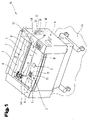
- FIG. 3 is a detailed diagram of the processing device illustrated in FIG. 2 , seen from an angle;
- FIG. 4 is a detailed diagram showing the processing device illustrated FIG. 3 in detail from a side view with a composite component illustrated in section;
- FIG. 5 a detailed diagram showing another embodiment of a processing device, seen from an angle
- FIG. 6 illustrates one possible embodiment of a structure for controlling and automatically controlling the components of the processing device proposed by the invention, shown in a schematic block diagram
- FIG. 7 is a simplified diagram of a layout of a stamp plate element and stamp pad which can be set up and produced by means of the processing unit.
- FIG. 1 shows a processing device 1 proposed by the invention for processing at least composite components 2 , comprising at least a support device 3 , in particular a stamp pad holder, and a stamp pad 4 , which processing device 1 , in addition to processing composite components 2 , may also be used to produce or process other workpieces, such as stamp plates 5 , for example, in particular stamp plate blanks, the parts to be processed also being referred to as workpieces hereafter.
- the processing device 1 has at least one material-removing unit 6 and a handling unit 7 .
- Workpieces disposed on a workpiece holder 8 can therefore be processed by means of the material-removing unit 6 , in which case the processing sequence can be controlled and/or regulated by means of at least one control unit 9 which is and/or can be connected to the handling unit 7 , and at least one operating head 10 of the material-removing unit 6 can be adjusted, in particular can be moved, on the basis of signals pre-set by means of the control unit 9 with a view to controlling and regulating the handling unit 7 , preferably relative to a workpiece holder 8 and the workpiece.
- the dividing gap 13 is preferably produced on the composite component 2 in such a way that the stamp pad 4 has a continuous recess or cut through its thickness and the pad parts 11 are completely separated from one another, as will be described in more detail below and as may be seen from FIG. 4 .
- the processing device 1 is preferably designed for use with a production system 14 of the type illustrated in FIG. 1 . Accordingly, the production system 14 is positioned on a support surface 15 and, in the embodiment illustrated as an example, also has an interior 16 , in which the workpieces are process by means of the processing device 1 , in particular the material-removing unit 6 and the handling unit 7 . In order to accommodate workpieces, a support base 17 is provided in the interior 16 constituting a workpiece holder 8 .
- the workpiece holder 8 may be provided in the form of clamping and/or positioning mechanisms for retaining workpieces in a fixed position, in which case the workpiece holder 8 may be provided in the form of mechanical clamping mechanisms, such as vices for example, or, in order to fix the position, form-fitting positioning frames to accommodate the workpieces.
- the workpiece holder 8 may be placed not in an interior 16 but on any surface suitable for accommodating workpieces.
- FIG. 1 merely showing a preferred embodiment of a production system with which the processing device 1 can be used.
- the processing device 1 is provided in the form of a modular unit designed to extend an already known production system 14 by means of which the advantage offered by the invention can be achieved.
- FIG. 2 illustrates the processing device 1 with the handling unit 7 and the material-removing unit 6 .
- the operating head 10 is optionally one of several components of the effector unit 19 and co-operates therewith.
- the handling unit 7 is designed to displace at least the effector unit 19 at least linearly, preferably along two axes in a Cartesian co-ordinate system, rendering the effector unit 19 displaceable at least in an X direction 20 and a Y direction 21 . Accordingly, the effector unit 19 is displaceable in a two-dimensional XY plane extending parallel with the support base 17 , for example, and, in order to control and/or regulate the handling unit 7 , it is connected to the control unit 9 .
- the handling unit 7 may have a guide system 26 , in particular a linear guide 27 , and a drive mechanism 22 , which drive mechanism 22 has a rotary motor 23 and transmission elements 24 . As illustrated in FIG.
- the rotating movement produced by the rotary motor 23 is transmitted via the transmission elements 24 , provided in the form of belts, to a device for converting a rotating motion into a linear motion, for example to a rack arrangement or a spindle drive assembly, in which case the effector unit 19 is purposely designed as the last moving member of the resultant kinematic chain of motion and is therefore linearly displaceable in the X direction 20 along a support arm 25 by guide system 26 constituting a linear guide 27 .
- the drive mechanism 22 In order to control and/or regulate the movement to be effected by the effector unit 19 in the XY plane, the drive mechanism 22 , in particular the rotary motor 23 in the embodiment illustrated as an example here, is connected via a control line 30 to the control unit 9 , and another control line 30 may be provided for controlling and/or regulating the drive mechanism 29 .
- the control unit 9 is able to control the handling unit 7 in order to position the effector unit 19 at any point within a possible operating range, preferably in the XY plane, along a cutting path.
- the handling unit 7 may also be designed for displacement within a three-co-ordinate system, in which case it would be possible to obtain a three-dimensional displacement of the effector unit 19 in three directions.
- the material-removing unit 6 only its operating head 10 is displaceably disposed on a retaining unit 32 forming the effector unit 19 , in which case the equipment needed to generate the energy for removing material, e.g. kinetic, electrical, thermal energy, need not be disposed on the effector unit 19 and does not need to be coupled with it in displacement, which means that the components which have to be moved by the handling unit 7 may have a low volume and weight.
- the equipment needed to generate the energy for removing material e.g. kinetic, electrical, thermal energy
- this function is advantageously fulfilled using a radiation source 33 to generate an energy beam 34 , in particular because this means that the only transmission elements needed to direct the energy to the operating head 10 are deflector mirrors 35 and no other components are needed to transmit energy, whilst the radiation source 33 can be stationary-mounted, for example on a production system 14 .
- the system used to apply an energy beam 34 is preferably a laser system 36 with a laser head 37 co-operating with the effector unit 19 or disposed on it. Due to its particularly high efficiency, the use of a CO 2 laser has proved to be of particular advantage, although it would naturally also be possible to use any type of fixed-body, fluid, semiconductor and gas laser types.
- the laser radiation 38 generated by the radiation source 37 is transmitted via the deflector mirrors 35 to the laser head 37 so that the laser beam 38 emitted from the laser head 37 in the direction of the workpiece is transmitted to a substantially flat processing surface 39 , on a stamp pad top face of the composite component 2 where material is removed (see FIGS. 3 and 4 ).
- a focussing lens is disposed in the laser head 37 in order to generate a burning point, so that the composite component 2 can be split through a cutting depth 40 by focussing on the burning point within the composite components 2 accordingly, for example on the lowermost point of the cutting depth 40 , as illustrated in FIG.
- the cutting depth 40 may essentially be set by controlling the cutting speed, the power and a distance of the burning point from the operating head 10 . Since the structure of laser systems 36 is sufficiently well known from the prior art, their structure will not be explained in any further detail here.
- the stamp pad 4 is cut into several pad parts along cutting lines 43 across the dividing gap 13 .
- the cutting lines 43 are not restricted to any particular shape and, as illustrated, may be extend in a circular, arcuate, straight arrangement, etc., on the processing surface 39 of the composite component 2 , the cutting lines 43 being set by the control unit 9 , and at least the operating head 10 , in particular the effector unit 19 , is displaced or moved relative to the workpiece holder 8 , in particular the processing surface 39 of the composite component 2 , following, the cutting lines 43 , in order to remove material along the cutting line 43 .
- This displacement or movement of the handling unit 7 and the removal of material by the material-removing unit 6 is controlled and/or regulated by the control unit 9 . Consequently, material can be removed or detached from a processing zone of the stamp pad 4 continuously across the thickness 41 of the stamp pad 4 along the cutting lines 43 in order to produce the dividing gap 13 , thereby forming on the pad parts 11 respective oppositely lying cut surfaces 45 spaced at a distance apart from one another by the dividing gap 13 , so that the pad parts 11 are completely separated from one another by peripheral surfaces 44 and cut surfaces 45 around the periphery.
- the dividing gaps 13 are bounded in a virtually fluid-proof arrangement with respect to the stamping inks contained in the pad parts 11 , thereby preventing any admixing of different types of stamping ink.
- material can also be removed on the support device 3 , in particular if retaining projections extend in the direction of the stamp pad 4 in order to retain it on the support device 3 (see composite component 2 in FIG. 3 ), to enable a complete separation of the pad parts 11 .
- the processing device 1 has an ink dispenser unit 46 , which is designed to dispense stamping ink 47 , in particular inking fluids, as and when required.
- the ink dispenser unit 46 has at least one dispensing unit 48 with at least one dispenser nozzle 49 .
- the output side of the ink dispenser unit 46 preferably has at least one dispensing unit 48 for stamping ink 47 and an ink delivery system, in particular one or more fluid lines 50 for delivering stamping ink 47 to the dispensing unit 48 and one or more ink container 51 (see FIG. 1 ).
- stamping ink 47 is delivered to the dispenser nozzle 49 via the fluid lines 50 , the flow passages 52 of which, on the input side, are in flow connection with an interior for accommodating stamping ink 47 in the ink containers 51 , whilst at the output side they have a flow connection to a housing chamber 53 connected to a discharge passage 54 of the dispenser nozzle 49 , so that stamping ink 47 can be discharged through an outlet orifice 55 , in particular the discharge passage 54 .
- the outlet orifice 55 is therefore able to deliver stamping ink 47 via one or more fluid lines 50 with a flow connection to the outlet orifice 55 and the housing chamber 53 for different types of stamping inks 47 .
- the fluid lines 50 may have specific flexible material properties enabling them to deform and in particular may be made from elastic synthetic material so that the fluid lines 50 can be run in a manner known from the prior art in a crawler-type line carrier or a line guide system, as partially illustrated in FIGS. 2 to 5 , in a flexible and compact bundle to the effector unit 19 , in particular to the dispensing unit 48 .
- the outlet orifice 55 could be provided directly on the ink container 51 , for example, and the ink container 51 could be designed to dispense the stamping ink 47 directly, in which case they will co-operate with the effector unit 19 .
- the at least one dispensing unit 48 is preferably disposed on the effector unit 19 , in which case, although this embodiment is not illustrated, the dispensing unit 48 and the operating head 10 can be displaced independently of one another and several effector units co-operate with the processing device 1 .
- the advantage of the possible design of the ink dispenser unit 46 with a dispensing unit 48 described above is that only the dispensing unit 48 of the ink dispenser unit 46 is a spatially displaceable element and the ink container 51 is then disposed in a stationary arrangement on a production system 14 by preference (see FIG. 1 ).
- the effector unit 19 can be displaced by means of the control unit 9 on the basis of a controllable pre-set desired value in at least the XY plane.
- the effector unit 19 incorporates the dispensing unit 48 and operating head 10 , which are connected to the retaining unit 32 , in particular are mounted on it so as to be prevented from moving.
- the retaining unit 32 is therefore designed to be displaceable in the manner described above by means of the handling unit 7 , preferably in an XY plane.
- stamping ink 47 can be delivered to application points 56 on the pad top face 57 of the stamp pad 4 or pad parts 11 .
- Stamping ink 47 is preferably applied or supplied to the pad parts 11 by means of ink drops 58 , which are dripped onto one or more ink application points 56 on the pad top face 57 , in which case the outlet orifice 55 of the dispenser nozzle 49 is positioned substantially vertically above an ink application point 56 on the pad part 11 so that an ink drop 58 can then be discharged, in other words at least the dispenser nozzle 49 , in particular the outlet orifice 55 , of the ink dispenser unit 46 is positioned above the corresponding pad part 11 by means of the handling unit 7 in readiness for dispensing stamping ink 57 to ink application points 52 . Accordingly, stamping ink 47 can be dispensed in a specific quantity and uniformly onto the pad parts 11 , as will be
- each of the pad parts 11 can be provided with stamping ink 47 by means of the ink dispenser unit 46 , for which purpose it is preferable to apply different types of stamping inks, in particular differently coloured stamping inks 47 , on different pad parts 11 , thereby producing a stamp pad 4 with regions formed by the different pad parts 11 in which different types of stamping ink 47 are stored.
- the stamp pad 4 is preferably of a design known from the prior art and is designed accordingly to accommodate or store stamping ink 47 and, when the stamp pad 4 makes contact with the pad top face 57 , to dispense or ink the corresponding object for example, in particular a stamp plate 5 .
- At least two surface part-regions 59 are set, preferably on the pad top face 57 , by means of the control unit 9 co-operating with the processing device 1 , thereby setting the cutting lines 43 in the mutually adjoining surface part-regions 59 along which material will then be removed.
- the surface part-regions 59 thus correspond to the surface portions on the pad-top face 57 , through which different types of stamping ink 47 , in particular differently coloured stamping ink, will be dispensed.
- the cut is made in the pad parts 11 , and—as illustrated in FIG. 4 —the cut surfaces 45 of the dividing gaps 13 are preferably produced so that they stand essentially vertically on the pad top face 57 and a distance 60 between the cut surfaces 45 is kept as short as possible.
- the distance 60 may be approximately 1 mm, for example between 0.1 mm and 2 mm, and this distance 60 of the cut surfaces 45 may optionally be produced by several adjacent cutting lines 43 .
- the adjacent cutting lines 43 are spaced at a distance apart so that the desired distance 60 is achieved between the cut surfaces 45 of the dividing gap 13 once the cutting processes along all the cutting lines 43 have been completed.
- three cutting lines 43 may be disposed at a distance of approximately 0.3 mm from one another in order to obtain a distance 60 of approximately 1 mm after the cutting process.
- the distance 60 should be large enough to prevent or largely prevent any admixing of stamping inks 47 from different pad parts 11 due to the spacing.
- the advantage of removing the smallest possible amount of material across the distance 60 is that only a small amount of the surface of the pad top face 57 is removed and virtually the entire pad top face is suitable for dispensing stamping ink, for example more than 90% of the pad top face 57 . It would also be possible to remove part-regions corresponding to a region of the pad top face 57 with a large surface area on the stamp pad 4 .
- the control unit 9 co-operates with an input and/or output device 61 or the control unit 9 is part of the input and/or output device, in which case the input and/or output device 61 is preferably a computer unit 62 , in particular a personal computer or microprocessor controller.
- the breakdown into surface part-regions 59 on the pad top face 57 can be set up in an easy and user-friendly manner by means of this input and/or output device 61 because a diagram 61 c , in particular a stamp plate 5 , is displayed on an output unit 61 a , in particular a monitor, and the diagram 61 c can be sub-divided into different part regions 63 by means of an input unit 61 b.
- FIG. 6 illustrates the principle underlying the structure of a control unit 9 together with the components of the processing device 1
- FIG. 7 shows an example of a stamp plate layout schematically illustrated by the diagram 61 c on an input and/or output device 61 .
- This division into part regions 63 can be produced by fixing engraved patterns on a diagram 61 c displaying a stamp plate bottom face, it being possible for the engraved patterns to be of any freely selectable shape, and the colour to be printed using the finished stamp plate 5 or stamp pad 4 engraved pattern can be fixed by means of an appropriate engraved pattern entered at the input and/or output device 61 , in other words the layout of a multi-coloured stamp can be defined.
- FIG. 7 illustrates a stamp layout of this type displayed by a diagram 61 c , in which the different cutting lines 43 for separating the stamp pads 4 into the pad parts 11 and the cutting lines 64 for separating the part regions 63 or the stamp plate 5 are applied to a stamp plate blank.
- all of the cutting lines 5 , 64 are set automatically, once the engraved patterns and the inks to be printed by it have been individually defined on the displayed stamp plate 5 by an operator and/or a previously set division of engraved patterns loaded from a memory for re-use.
- surface part-regions 59 are determined by the control unit 9 , in particular the computer unit 62 , on the basis of the fixed part regions 63 or engraved patterns on the diagram 61 c and the pad top face 57 is sub-divided.
- a stamp plate 5 for example a stamp plate blank
- the material removing device 6 in particular the laser system 36
- produces engravings in a known manner to produce the stamp plate 5 for example using an engraving process known from the prior art.
- the surface part-regions 59 or cutting lines 43 can be imparted to the stamp pad 4 by means of the control unit, after which the stamp pad 4 is separated into the pad parts 11 .
- the various pad parts 11 are preferably then provided with different types of stamping ink 47 depending on colour attributes in the part regions 63 or the engraved patterns set at the input and/or output device 61 , and in another process step, an engraved stamp plate 5 can be finished in a controlled manner by means of the control unit 9 on the basis of parameters pre-set at the input and/or output device 61 .
- the part regions 63 in which the engraved patterns, in particular a text, character, graphical character, etc., are disposed can be processed by the material-removing unit 6 so that the part regions 63 are slightly higher than the intermediate regions 61 d adjacent to them and/or the part regions 63 are preferably moved apart along the cutting line 64 .
- the intermediate region 61 d extending between the part regions 63 may be taken off the stamp plate holder, during a process to break and remove the connecting webs. This avoids any unintentional admixing of inks in adjacent part regions 63 on the stamp plate 5 because the flat connection of the part regions 63 along which ink might possibly converge has been removed.
- the computer unit 62 together with the software means operated on it are configured so that the control and/or regulating processes and computation routines of the control unit 9 can be run by special software means specially designed to control and regulate the processing device 1 , in particular a formatting programme and a control programme.
- the control unit 9 can be connected to the latter via a control line 65 and the handling unit 7 described above can be connected via control lines 30 to the control unit 9 , whilst control lines 66 connect the ink dispenser unit 46 to the control unit 9 for control and/or regulation purposes. As illustrated by dotted-dashed lines in FIG.
- control unit 9 and/or the processing device 1 may incorporate one or more electronic interfaces, by means of which the processing device 1 proposed by the invention and its components can be connected to the control unit 9 in order to transmit data and/or signals. Consequently, control units 9 that are already in use on production systems 14 can be used with the processing device 1 and set up by means of a software extension on the control unit 9 to enable the latter to control the processing device 1 .
- a metering unit 67 of the ink dispenser unit 46 for controlling and regulating the type of stamping ink 47 to be dispensed and/or the quantities of stamping ink 47 to be dispensed from one or more outlet orifices 55 is connected via the control line 66 to the control unit 9 , in particular for electronic signal and/ or data transmission.
- any devices known from the prior art may be used as ejection mechanisms for the metering unit 67 , such as piezoelectric elements, although in the preferred embodiment illustrated, the metering unit 67 is provided in the form of a pressure generator 68 .
- the pressure generator 68 preferably has an active pneumatic connection via lines 69 to the ink containers 51 so that an over-pressure can be generated at least briefly in the ink container 51 and/or the flow passages 52 of the fluid lines 50 , causing stamping ink 47 to be ejected from the outlet orifice 55 .
- shut-off element 70 in particular a check valve 71 , preferably in the region of the discharge passage 54 and/or in the flow passages 52 —see FIG. 4 —which moves into a position which provides a fluid-proof seal in the discharge passage 54 at ambient pressure or at a negative pressure, in particular a pressure lower than a release pressure needed to open a shut-off device to provide a passage, in the flow passages 52 or the housing chamber 53 , and when an over-pressure is applied, for example, moves into a releasing position allowing fluid to pass so that stamping ink 47 or ink drops 58 can be dispensed.
- a shut-off element 70 in particular a check valve 71 , preferably in the region of the discharge passage 54 and/or in the flow passages 52 —see FIG. 4 —which moves into a position which provides a fluid-proof seal in the discharge passage 54 at ambient pressure or at a negative pressure, in particular a pressure lower than a release pressure needed to open a shut-off device to provide a passage
- Stamping ink 47 is preferably applied to the pad parts 11 on the basis of several ink application points 56 on the pad top face 57 by means of the dispensing unit 48 , which is moved alongside a grid pattern of ink application points and ink drops 58 containing one or more quantities of optionally different fluid are dispensed on the basis of control signals pre-set in the control unit 9 and forwarded to the metering unit 67 .
- ink drops 58 By applying ink drops 58 to the pad top face 57 in this grid or matrix pattern, preferably the same quantities of ink are essentially stored in the different regions of the pad parts 11 so that when the pad top face 57 makes contact by means of a stamp plate 5 , ink can be applied to it uniformly enabling stamp prints to be produced with a uniform colour intensity.
- FIG. 5 also illustrates another particularly preferred embodiment with an ink dispenser unit 46 .
- the dispensing unit 48 has several dispenser nozzles 49 , each of which dispenser nozzles 49 preferably applies ink to the stamp pad 4 but each applying a separate type of stamping ink 47 , and the dispenser nozzles 49 , in particular their outlet orifices 55 , expediently each have a flow connection to a flow passage 52 of a fluid line 50 .
- the advantage of this is that there can be no undesirable admixing of different types of stamping inks 47 , obviating the need to provide any additional means for keeping the types separate, for example in the housing chamber 53 illustrated in FIG. 4 .
- the separating material can be dispensed from a displaceable dispensing unit on the effector unit 19 , for example, in which case control and/or regulation of the dispensing unit and the approach to the filling process may be based on the same systems as those described above for applying the stamping ink.
- the separating material might be adhesive, sealing compound, etc., of a type known form the prior art.
- FIGS. 1 ; 2 , 3 , 4 ; 5 ; 6 ; 7 may be construed as independent solutions proposed by the invention.
- the associated objectives and solutions may be found in the detailed descriptions of these drawings.
Landscapes
- Engineering & Computer Science (AREA)
- Physics & Mathematics (AREA)
- Optics & Photonics (AREA)
- Plasma & Fusion (AREA)
- Mechanical Engineering (AREA)
- Coating Apparatus (AREA)
- Press Drives And Press Lines (AREA)
- Grinding Of Cylindrical And Plane Surfaces (AREA)
Applications Claiming Priority (3)
| Application Number | Priority Date | Filing Date | Title |
|---|---|---|---|
| AT0047903A AT413200B (de) | 2003-03-26 | 2003-03-26 | Verfahren sowie vorrichtung zur bearbeitung von aus einer trageeinrichtung und einem stempelkissen gebildeten verbundteilen |
| ATA479/2003 | 2003-03-26 | ||
| PCT/AT2004/000061 WO2004085110A1 (de) | 2003-03-26 | 2004-03-02 | Verfahren sowie vorrichtung zur bearbeitung von aus einer trageeinrichtung und einem stempelkissen gebildeten verbundteilen |
Publications (2)
| Publication Number | Publication Date |
|---|---|
| US20060196326A1 US20060196326A1 (en) | 2006-09-07 |
| US7652225B2 true US7652225B2 (en) | 2010-01-26 |
Family
ID=33034703
Family Applications (1)
| Application Number | Title | Priority Date | Filing Date |
|---|---|---|---|
| US10/550,249 Expired - Fee Related US7652225B2 (en) | 2003-03-26 | 2004-03-02 | Method and device for machining composite parts formed from a carrier device and a stamping pad |
Country Status (10)
| Country | Link |
|---|---|
| US (1) | US7652225B2 (de) |
| EP (1) | EP1606075B1 (de) |
| CN (1) | CN1764514B (de) |
| AT (2) | AT413200B (de) |
| CA (1) | CA2520301C (de) |
| DE (1) | DE502004001904D1 (de) |
| ES (1) | ES2276284T3 (de) |
| PL (1) | PL1606075T3 (de) |
| WO (1) | WO2004085110A1 (de) |
| ZA (1) | ZA200508357B (de) |
Cited By (5)
| Publication number | Priority date | Publication date | Assignee | Title |
|---|---|---|---|---|
| US20110174789A1 (en) * | 2010-01-21 | 2011-07-21 | Tong Li | Portable engraving system |
| US10040305B2 (en) | 2013-04-22 | 2018-08-07 | Colop Stempelerzeugung Skopek Gesellschaft M.B.H. & Co. Kg. | Plate carrier having a grid pattern for a self-inking stamp and production method |
| US10654127B2 (en) | 2017-10-24 | 2020-05-19 | Tong Li | Engraving system and method of operation thereof |
| US20220143753A1 (en) * | 2016-10-06 | 2022-05-12 | Trotec Laser Gmbh | Method for engraving, marking and/or inscribing a workpiece with a laser plotter and laser plotter for the same |
| US11446761B2 (en) * | 2020-03-06 | 2022-09-20 | Tong Li | Engraving machine |
Families Citing this family (12)
| Publication number | Priority date | Publication date | Assignee | Title |
|---|---|---|---|---|
| US8101883B2 (en) | 2006-04-27 | 2012-01-24 | Universal Laser Systems, Inc. | Laser-based material processing systems and methods for using such systems |
| AT514337B1 (de) * | 2013-05-15 | 2015-06-15 | Trodat Gmbh | System zum Erstellen und Erzeugen einer Stempelplatte |
| WO2015103654A2 (de) * | 2014-01-10 | 2015-07-16 | Trodat Gmbh | Bearbeitungssystem für mehrere unterschiedliche werkstücke |
| USD823378S1 (en) | 2015-06-10 | 2018-07-17 | Trodat Gmbh | Hand stamp |
| AT517321A1 (de) | 2015-06-10 | 2016-12-15 | Trodat Gmbh | Stempel |
| AT517328B1 (de) | 2015-06-10 | 2024-06-15 | Trodat Gmbh | Stempel, ein Stempelkissen und eine Verschlusskappe |
| AT517322A1 (de) | 2015-06-10 | 2016-12-15 | Trodat Gmbh | Stempel und Abdruckeinheit, insbesondere als Ersatzteil für einen Stempel |
| AT517318B1 (de) | 2015-06-10 | 2024-07-15 | Trodat Gmbh | Stempel und Abdruckeinheit |
| USD820350S1 (en) | 2015-12-10 | 2018-06-12 | Trodat Gmbh | Stamp pad |
| AT518735B1 (de) | 2016-06-09 | 2024-09-15 | Trodat Gmbh | Antriebseinheit, Bandeinheit, Brücke, Mitnehmer und Stempel hierfür |
| CN112248672A (zh) * | 2020-10-22 | 2021-01-22 | 湖北浩派沃科技服务有限公司 | 一种办公用高效快速盖章机 |
| CN114312070B (zh) * | 2021-12-22 | 2024-02-13 | 胡金钱 | 多功能区智能章模装置及生成多功能区章模图像的方法 |
Citations (19)
| Publication number | Priority date | Publication date | Assignee | Title |
|---|---|---|---|---|
| US3009440A (en) | 1958-06-10 | 1961-11-21 | Hans F Kent | Stamp pads |
| US4900379A (en) * | 1988-05-20 | 1990-02-13 | The Boeing Company | Method for producing composite materials |
| US5003153A (en) * | 1989-07-04 | 1991-03-26 | Kabushiki Kaisha | Laser beam machining and apparatus therefor |
| SU1689473A1 (ru) * | 1989-12-26 | 1991-11-07 | Alma Atinskoe N Proizv Ob Legk | Уctpoйctbo для mapkиpobkи tekctильhoгo matepиaлa |
| US5132510A (en) * | 1990-09-04 | 1992-07-21 | Trumpf, Inc. | Laser machine assembly for flow of workpieces therethrough and method of using same |
| FR2675740A1 (fr) * | 1991-04-25 | 1992-10-30 | Scb Distribution Sarl | Tampon encreur multi-couleurs. |
| JPH0732226A (ja) | 1993-07-20 | 1995-02-03 | Enplas Corp | ケースへのスポンジ充填方法 |
| US5460757A (en) * | 1993-12-29 | 1995-10-24 | Topstamp, Inc. | Method for manufacturing pre-inked stamps |
| JPH0930097A (ja) * | 1995-07-13 | 1997-02-04 | Tanikawa Shoji Kk | 多色スタンプ及びその製造方法 |
| US5601644A (en) * | 1995-05-19 | 1997-02-11 | Tsukineko, Inc. | Multicolor stamp pad |
| JPH10193635A (ja) * | 1996-11-14 | 1998-07-28 | Seiko Epson Corp | インクジェット式記録装置用インクカートリッジの製造方法、及び再充填方法 |
| JPH10270843A (ja) * | 1997-03-28 | 1998-10-09 | Vacuum Metallurgical Co Ltd | 導電パターンの補修方法と装置 |
| JP2001205911A (ja) * | 2000-01-25 | 2001-07-31 | Teikoku Carbon Paper Kk | 連続捺印用カラースタンプ |
| US20020002416A1 (en) * | 1997-03-12 | 2002-01-03 | Herman Jr. James S. | Method and apparatus for transforming a part periphery to be cut from a patterned sheet material |
| US6423931B1 (en) | 2000-10-21 | 2002-07-23 | Trotec Produktions- Und Vertriebs Gmbh | Method of controlling the movement of a laser engraving head |
| JP2002248783A (ja) * | 2001-02-23 | 2002-09-03 | Canon Inc | インクジェット記録装置 |
| US6491361B1 (en) * | 2000-11-09 | 2002-12-10 | Encad, Inc. | Digital media cutter |
| US6908243B1 (en) * | 2003-12-30 | 2005-06-21 | Great Computer Corp. | Separable cutting mechanism for printer |
| US20060266239A1 (en) * | 2003-01-03 | 2006-11-30 | M&R Marking Systems, Inc. | Methods of making multi-color ink stamps |
Family Cites Families (1)
| Publication number | Priority date | Publication date | Assignee | Title |
|---|---|---|---|---|
| DE19715702A1 (de) * | 1997-04-15 | 1998-10-22 | Fraunhofer Ges Forschung | Verfahren zum selektiven Abtragen einer oder mehrerer Schichten |
-
2003
- 2003-03-26 AT AT0047903A patent/AT413200B/de not_active IP Right Cessation
-
2004
- 2004-03-02 CN CN2004800081253A patent/CN1764514B/zh not_active Expired - Fee Related
- 2004-03-02 US US10/550,249 patent/US7652225B2/en not_active Expired - Fee Related
- 2004-03-02 ES ES04716185T patent/ES2276284T3/es not_active Expired - Lifetime
- 2004-03-02 EP EP04716185A patent/EP1606075B1/de not_active Expired - Lifetime
- 2004-03-02 WO PCT/AT2004/000061 patent/WO2004085110A1/de not_active Ceased
- 2004-03-02 CA CA2520301A patent/CA2520301C/en not_active Expired - Fee Related
- 2004-03-02 AT AT04716185T patent/ATE344116T1/de active
- 2004-03-02 DE DE502004001904T patent/DE502004001904D1/de not_active Expired - Lifetime
- 2004-03-02 PL PL04716185T patent/PL1606075T3/pl unknown
- 2004-03-02 ZA ZA200508357A patent/ZA200508357B/en unknown
Patent Citations (19)
| Publication number | Priority date | Publication date | Assignee | Title |
|---|---|---|---|---|
| US3009440A (en) | 1958-06-10 | 1961-11-21 | Hans F Kent | Stamp pads |
| US4900379A (en) * | 1988-05-20 | 1990-02-13 | The Boeing Company | Method for producing composite materials |
| US5003153A (en) * | 1989-07-04 | 1991-03-26 | Kabushiki Kaisha | Laser beam machining and apparatus therefor |
| SU1689473A1 (ru) * | 1989-12-26 | 1991-11-07 | Alma Atinskoe N Proizv Ob Legk | Уctpoйctbo для mapkиpobkи tekctильhoгo matepиaлa |
| US5132510A (en) * | 1990-09-04 | 1992-07-21 | Trumpf, Inc. | Laser machine assembly for flow of workpieces therethrough and method of using same |
| FR2675740A1 (fr) * | 1991-04-25 | 1992-10-30 | Scb Distribution Sarl | Tampon encreur multi-couleurs. |
| JPH0732226A (ja) | 1993-07-20 | 1995-02-03 | Enplas Corp | ケースへのスポンジ充填方法 |
| US5460757A (en) * | 1993-12-29 | 1995-10-24 | Topstamp, Inc. | Method for manufacturing pre-inked stamps |
| US5601644A (en) * | 1995-05-19 | 1997-02-11 | Tsukineko, Inc. | Multicolor stamp pad |
| JPH0930097A (ja) * | 1995-07-13 | 1997-02-04 | Tanikawa Shoji Kk | 多色スタンプ及びその製造方法 |
| JPH10193635A (ja) * | 1996-11-14 | 1998-07-28 | Seiko Epson Corp | インクジェット式記録装置用インクカートリッジの製造方法、及び再充填方法 |
| US20020002416A1 (en) * | 1997-03-12 | 2002-01-03 | Herman Jr. James S. | Method and apparatus for transforming a part periphery to be cut from a patterned sheet material |
| JPH10270843A (ja) * | 1997-03-28 | 1998-10-09 | Vacuum Metallurgical Co Ltd | 導電パターンの補修方法と装置 |
| JP2001205911A (ja) * | 2000-01-25 | 2001-07-31 | Teikoku Carbon Paper Kk | 連続捺印用カラースタンプ |
| US6423931B1 (en) | 2000-10-21 | 2002-07-23 | Trotec Produktions- Und Vertriebs Gmbh | Method of controlling the movement of a laser engraving head |
| US6491361B1 (en) * | 2000-11-09 | 2002-12-10 | Encad, Inc. | Digital media cutter |
| JP2002248783A (ja) * | 2001-02-23 | 2002-09-03 | Canon Inc | インクジェット記録装置 |
| US20060266239A1 (en) * | 2003-01-03 | 2006-11-30 | M&R Marking Systems, Inc. | Methods of making multi-color ink stamps |
| US6908243B1 (en) * | 2003-12-30 | 2005-06-21 | Great Computer Corp. | Separable cutting mechanism for printer |
Cited By (7)
| Publication number | Priority date | Publication date | Assignee | Title |
|---|---|---|---|---|
| US20110174789A1 (en) * | 2010-01-21 | 2011-07-21 | Tong Li | Portable engraving system |
| US8309881B2 (en) * | 2010-01-21 | 2012-11-13 | Tong Li | Portable engraving system |
| US10040305B2 (en) | 2013-04-22 | 2018-08-07 | Colop Stempelerzeugung Skopek Gesellschaft M.B.H. & Co. Kg. | Plate carrier having a grid pattern for a self-inking stamp and production method |
| US20220143753A1 (en) * | 2016-10-06 | 2022-05-12 | Trotec Laser Gmbh | Method for engraving, marking and/or inscribing a workpiece with a laser plotter and laser plotter for the same |
| US11958130B2 (en) * | 2016-10-06 | 2024-04-16 | Trotec Laser Gmbh | Method for engraving, marking and/or inscribing a workpiece with a laser plotter and laser plotter for the same |
| US10654127B2 (en) | 2017-10-24 | 2020-05-19 | Tong Li | Engraving system and method of operation thereof |
| US11446761B2 (en) * | 2020-03-06 | 2022-09-20 | Tong Li | Engraving machine |
Also Published As
| Publication number | Publication date |
|---|---|
| WO2004085110A1 (de) | 2004-10-07 |
| DE502004001904D1 (de) | 2006-12-14 |
| EP1606075A1 (de) | 2005-12-21 |
| ES2276284T3 (es) | 2007-06-16 |
| PL1606075T3 (pl) | 2007-05-31 |
| ATA4792003A (de) | 2005-05-15 |
| AT413200B (de) | 2005-12-15 |
| EP1606075B1 (de) | 2006-11-02 |
| ATE344116T1 (de) | 2006-11-15 |
| US20060196326A1 (en) | 2006-09-07 |
| CN1764514B (zh) | 2010-08-04 |
| ZA200508357B (en) | 2007-03-28 |
| CA2520301C (en) | 2012-01-24 |
| CN1764514A (zh) | 2006-04-26 |
| CA2520301A1 (en) | 2004-10-07 |
Similar Documents
| Publication | Publication Date | Title |
|---|---|---|
| US7652225B2 (en) | Method and device for machining composite parts formed from a carrier device and a stamping pad | |
| US11440251B2 (en) | Device for the generative manufacturing of three-dimensional components | |
| JP6021796B2 (ja) | 三次元的印刷方法 | |
| EP0266344B1 (de) | Flüssigkeitsstrahldrucker | |
| CN106102933B (zh) | 涂布装置及涂布方法 | |
| US11202694B2 (en) | Method of making a dental articles | |
| KR101713420B1 (ko) | 다중소재 토출 노즐 헤드 및 토출 방법 | |
| KR20140074974A (ko) | 액체 재료의 토출 장치 및 토출 방법 | |
| JP7037978B2 (ja) | 化粧料の製造方法 | |
| KR102275110B1 (ko) | 유지 지그 생성 장치 | |
| US20050212184A1 (en) | Method and device for producing a stamp | |
| JPH0232903A (ja) | 練状化粧剤用多色充填機 | |
| JP6955496B2 (ja) | 接着剤分注装置 | |
| EP4269070A1 (de) | 3d-druckerkartusche und 3d-drucker | |
| JP7717463B2 (ja) | 化粧品製造方法及び化粧品製造装置 | |
| CN213593959U (zh) | 一种激光雕刻机用多彩印章印台切割注油装置 | |
| CN110641170A (zh) | 一种新型产品凹面点印方法 | |
| JP2568418B2 (ja) | 粘状化粧剤用多色充填機 | |
| HK1230541A1 (en) | Application device and application method |
Legal Events
| Date | Code | Title | Description |
|---|---|---|---|
| AS | Assignment |
Owner name: TROTEC PRODUKTIONS U. VERTRIEBS GMBH, AUSTRIA Free format text: ASSIGNMENT OF ASSIGNORS INTEREST;ASSIGNOR:FAZENY, STEPHAN;REEL/FRAME:017119/0593 Effective date: 20050825 |
|
| STCF | Information on status: patent grant |
Free format text: PATENTED CASE |
|
| FPAY | Fee payment |
Year of fee payment: 4 |
|
| FPAY | Fee payment |
Year of fee payment: 8 |
|
| FEPP | Fee payment procedure |
Free format text: MAINTENANCE FEE REMINDER MAILED (ORIGINAL EVENT CODE: REM.); ENTITY STATUS OF PATENT OWNER: LARGE ENTITY |
|
| LAPS | Lapse for failure to pay maintenance fees |
Free format text: PATENT EXPIRED FOR FAILURE TO PAY MAINTENANCE FEES (ORIGINAL EVENT CODE: EXP.); ENTITY STATUS OF PATENT OWNER: LARGE ENTITY |
|
| STCH | Information on status: patent discontinuation |
Free format text: PATENT EXPIRED DUE TO NONPAYMENT OF MAINTENANCE FEES UNDER 37 CFR 1.362 |
|
| FP | Lapsed due to failure to pay maintenance fee |
Effective date: 20220126 |