US7628390B2 - Installation and method for the lifting of folded printed products from a conveyor - Google Patents
Installation and method for the lifting of folded printed products from a conveyor Download PDFInfo
- Publication number
- US7628390B2 US7628390B2 US11/561,637 US56163706A US7628390B2 US 7628390 B2 US7628390 B2 US 7628390B2 US 56163706 A US56163706 A US 56163706A US 7628390 B2 US7628390 B2 US 7628390B2
- Authority
- US
- United States
- Prior art keywords
- lifting
- saddle
- support shoulder
- printed product
- section
- Prior art date
- Legal status (The legal status is an assumption and is not a legal conclusion. Google has not performed a legal analysis and makes no representation as to the accuracy of the status listed.)
- Expired - Fee Related, expires
Links
- 238000009434 installation Methods 0.000 title claims abstract description 32
- 238000000034 method Methods 0.000 title claims abstract description 16
- 238000012545 processing Methods 0.000 claims abstract description 6
- 238000005452 bending Methods 0.000 claims description 10
- 238000007599 discharging Methods 0.000 claims 1
- 239000002184 metal Substances 0.000 description 18
- 238000003462 Bender reaction Methods 0.000 description 4
- 229910000831 Steel Inorganic materials 0.000 description 3
- 239000010959 steel Substances 0.000 description 3
- 238000010276 construction Methods 0.000 description 2
- 239000007787 solid Substances 0.000 description 2
- 229910000639 Spring steel Inorganic materials 0.000 description 1
- 239000011230 binding agent Substances 0.000 description 1
- 238000012937 correction Methods 0.000 description 1
- 238000013461 design Methods 0.000 description 1
- 238000007373 indentation Methods 0.000 description 1
- 238000005259 measurement Methods 0.000 description 1
- 230000001960 triggered effect Effects 0.000 description 1
Images



Classifications
-
- B—PERFORMING OPERATIONS; TRANSPORTING
- B42—BOOKBINDING; ALBUMS; FILES; SPECIAL PRINTED MATTER
- B42C—BOOKBINDING
- B42C1/00—Collating or gathering sheets combined with processes for permanently attaching together sheets or signatures or for interposing inserts
- B42C1/12—Machines for both collating or gathering and permanently attaching together the sheets or signatures
-
- B—PERFORMING OPERATIONS; TRANSPORTING
- B65—CONVEYING; PACKING; STORING; HANDLING THIN OR FILAMENTARY MATERIAL
- B65H—HANDLING THIN OR FILAMENTARY MATERIAL, e.g. SHEETS, WEBS, CABLES
- B65H3/00—Separating articles from piles
- B65H3/26—Separating articles from piles by separators engaging folds, flaps, or projections of articles
-
- B—PERFORMING OPERATIONS; TRANSPORTING
- B65—CONVEYING; PACKING; STORING; HANDLING THIN OR FILAMENTARY MATERIAL
- B65H—HANDLING THIN OR FILAMENTARY MATERIAL, e.g. SHEETS, WEBS, CABLES
- B65H39/00—Associating, collating, or gathering articles or webs
-
- B—PERFORMING OPERATIONS; TRANSPORTING
- B65—CONVEYING; PACKING; STORING; HANDLING THIN OR FILAMENTARY MATERIAL
- B65H—HANDLING THIN OR FILAMENTARY MATERIAL, e.g. SHEETS, WEBS, CABLES
- B65H2301/00—Handling processes for sheets or webs
- B65H2301/40—Type of handling process
- B65H2301/43—Gathering; Associating; Assembling
- B65H2301/436—Gathering; Associating; Assembling on saddles
-
- B—PERFORMING OPERATIONS; TRANSPORTING
- B65—CONVEYING; PACKING; STORING; HANDLING THIN OR FILAMENTARY MATERIAL
- B65H—HANDLING THIN OR FILAMENTARY MATERIAL, e.g. SHEETS, WEBS, CABLES
- B65H2301/00—Handling processes for sheets or webs
- B65H2301/40—Type of handling process
- B65H2301/44—Moving, forwarding, guiding material
- B65H2301/447—Moving, forwarding, guiding material transferring material between transport devices
- B65H2301/4471—Grippers, e.g. moved in paths enclosing an area
- B65H2301/44712—Grippers, e.g. moved in paths enclosing an area carried by chains or bands
Definitions
- the invention concerns an installation and a method for the lifting of folded printed products from a conveyor.
- CH 683 767 A5 reveals a method for the withdrawal of bound and folded printed products from the supports of a gatherer-stitcher.
- the printed products are conveyed upon a saddle-shaped, lightly built support to a binding device.
- the supports comprise a ridge-like support shoulder supporting the folded printed products.
- the support shoulders comprise on one hand recesses for bending installations that can be pushed against the support shoulders from below, and on the other recesses for ejection tappets.
- a binder wheel conveys the supports and a bending installation is conducted through the appropriate recess of the support into the binding position.
- the printed product is lifted from the support shoulder by the ejection tappets pushing through further recesses in the support shoulder and can be extracted e.g. by grippers. Consequently, the lifting tappets and the bending installation, viewed alongside the support shoulder, must be situated in different places. Therefore the possibilities for the positioning of the binding locations and the gripping points are limited.
- EP 0 202 507 A3 demonstrates thin rod-shaped supports, across which the printed products are hung.
- a bending installation or anvil is conducted from below toward the supports and lifts the printed products from the support.
- the printed products now lie upon the bending installation and are stapled or stitched. Subsequently the bending installation is retracted and the printed products are deposited upon the supports.
- a blade is conducted past the thin support from below, so that the printed products are lifted and gripped by a pair of rollers.
- the collective conveyor comprises a carrier ledge forming a ridge and equipped with metal prop sheets on either side.
- the printed product lies with the fold on top of the carrier ledge and the metal prop sheets.
- lifting pins are swivelled through slots in the carrier ledge, so that the printed products are lifted as well as conveyed along the carrier ledge.
- additional clamping tools can slide under the raised printed product, lift it from the collective conveyor and take it away.
- the saddle thus comprises a counter tool for the processing of the printed products straddled across the saddle.
- a means of lifting extends alongside and parallel to the saddle and the means of lifting is situated at right angles to a support shoulder of the saddle and staggered in relation to the counter tool.
- the support shoulder extends along the entire length of the saddle without recesses for a means of lifting.
- the term “length” of the saddle relates here and in the following to the direction of the furthest expansion of the support shoulder, i.e. the direction parallel to the fold of the printed product.
- the transverse direction of the support shoulder runs vertically to that. This transverse direction is in turn parallel to a longitudinal or conveying direction of a collective system conveying the saddles.
- the support shoulder extends along the entire length of the saddle without any recesses whatsoever. Accordingly the saddle can be of a slim and yet solid and stable design.
- the counter tool for example, a bending device for a binding installation
- a bending device for a binding installation is flexibly mounted or firmly connected to the support shoulder, or even fashioned in a single unit as part of the support shoulder. Consequently several bending devices can be situated along the support shoulder, which can then also be referred to as a girder.
- an upper edge of the means of lifting extends parallel to the support shoulder for the entire length of the upper edge. As the means of lifting is lifted, the inside of the fold therefore lies on the upper edge for the entire length.
- an upper edge of the means of lifting extends in some first regions parallel to the support shoulder, wherein the printed product is supported while being lifted by these first ranges.
- the upper edge comprises an offset or a recess or a depression in relation to the first region.
- the printed product is not cleared but is lowered back on to the support shoulder by the lifting device and remains in the gathering installation for fault correction.
- the means of lifting is a flat plate, for example, a metal sheet.
- a metal sheet In a lower position the metal sheet hugs a flank of the saddle, so that the contour of the saddle is not substantially altered by the adjacent metal sheet.
- the metal sheet is parallel movable in a sliding guide and is shifted parallel into an upper position for the lifting of the printed products. Therein an upper edge of the metal sheet moves away from the saddle and the printed product lies on top of this upper edge.
- the offset of the upper edge mentioned above is advantageously formed by a recess or indentation in the upper region of the plate.
- the means of lifting is a wire frame.
- the wire frame is conducted at both longitudinal ends of the saddle in a parallel guide allowing a parallel shift vertically to the longitudinal direction of the support shoulder.
- the wire frame runs either completely parallel to the support shoulder or is staggered in at least one area as explained above.
- the means of lifting can be a flat plate with its upper edge pushing into the fold of the printed products from inside.
- This plate too can, in line with the offset of the upper edge, comprise a gap, the position of which along the support shoulder corresponds with the position of a gripper or thickness gauge.
- the installation comprises two means of lifting.
- the first means of lifting is positioned on a leading side of the saddle and the second means of lifting on a trailing side of the saddle (with regard to the conveying direction and the transverse direction of the support shoulder, respectively).
- each variously positioned means of clamping can grip the printed product at these various points along the support shoulder.
- the upper edges of both means of lifting are advantageously of different shapes and comprise in particular one or several points with an offset in various regions along the support shoulder.
- the named method for the lifting of folded printed products from a conveyor including the following steps:
- the printed product can be gathered or just conveyed upon the support shoulder or upon the lifting device in the upper position.
- the lifting device is moved into the appropriate position as required, i.e. down for binding or up for gripping.
- these operations such as gathering, binding, gripping (incl. measurement) can be performed in any chosen order.
- the lifting device(s) therein enable the printed product to be brought into varying positions where the various tools can be activated. Certain operations demand a particular position of the lifting device while other operations, in particular the gathering, are in principle possible in any position of the lifting device.
- the method advantageously comprises as a further step the discharge of the printed product by the gripper. If the means of clamping is a thickness gauge the method comprises as further steps:
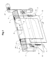
- FIGS. 1 and 2 show in perspective view a saddle with a wire frame as a lifting device in a lower and in an upper position.
- FIG. 3 shows a view with a metal sheet as a lifting device.
- FIG. 1 shows schematically a perspective view of a saddle 2 for the conveyance of a printed product 1 .
- the printed product 1 is folded and placed with the fold or spine across a support shoulder 3 of the saddle 2 .
- the support shoulder 3 comprises one or several counter tools such as benders 4 for a binding device.
- the benders 4 can be designed as passive or active, i.e. mobile themselves.
- the benders 4 and the saddle 2 must accordingly be of a solid and stable construction. This is in contrast to saddles 2 , which are intended for conveyance only and therefore of light and thin construction. In the case of such light saddles 2 , according to the state-of-the-art, a bending installation is moved into a binding position by a bind wheel for binding purposes.
- a lifting device 5 is situated on at least one side of the support shoulder 3 .
- the lifting device 5 extends along the longitudinal direction of the saddle 2 and the support shoulder 3 , thus essentially parallel to these.
- a transverse direction of the saddle 2 i.e. vertically to the named longitudinal direction
- the lifting device 5 is in a staggered position in relation to the support shoulder 3 .
- this transverse direction of the saddle 2 usually corresponds with the conveying F of the printed products 1 .
- the lifting device 5 can be situated in the transverse or conveying direction F in front of or behind the support shoulder 3 .
- sheets 12 , 12 ′ of spring steel extend essentially downward from the saddle 2 .
- a printed product 1 placed on the support shoulder 3 touches the steel sheets 12 , 12 ′.
- the lifting device(s) 5 are positioned on the inside of one of the steel sheets 12 , 12 ′ but on the outside of the support shoulder 3 , i.e. between the saddle 2 and one of the steel sheets 12 , 12 ′.
- the saddle 2 is suspended in a conveyor track by supports 27 and is conveyed upon a rotating conveyor track through the gathering system by elements not indicated, such as e.g. a chain.
- FIG. 1 the lifting device 5 is illustrated in a lower, inactive or basic position
- FIG. 2 the lifting device 5 is illustrated in an upper, active or elevated position.
- a gripper 11 is indicated by chain line.
- a frame end 7 serves as a control element by shifting the lifting device 5 as required against the force of a resetting spring 8 through a control cam at the conveyor track. Therein the lifting device 5 is moved essentially parallel through a parallel guide 6 . Of course the lifting device 5 can also be moved in other ways.
- the lifting device 5 is made of a firm wire and comprises at least one offset 9 of the upper edge 10 .
- the upper edge 10 comprises first not staggered regions 22 , 25 pushing the fold of the printed product 1 upwards from inside as the printed product 1 is being lifted. In the region of the staggering 9 from the first regions the elevated printed product 1 can be gripped and discharged by a gripper 11 , or the thickness of the printed product 1 can be measured without the lifting device 5 influencing the gauging.
- the wire frame advantageously comprises: a first section 21 and a sixth section 26 , each extending vertically to the support shoulder 3 and each sliding in an allocated parallel guide 6 , 6 ′, a second section 22 and a fifth section 25 , each running parallel to the support shoulder 3 and situated in collinear relation to each other, a staggered section 9 running parallel to the support shoulder 3 and staggered from the second section 22 and fifth section 25 , and a third section 23 between the second section 22 and the staggered section 9 as well as a forth section 24 between the staggered section 9 and the fifth section 25 .
- the upper edge 10 of the plate can comprise sections extending in the same manner as the named sections of the wire frame.
- FIG. 3 shows a relevant embodiment of the invention with a metal sheet 15 as a lifting device 5 .
- the support 27 of the saddle 2 is indicated by chain line.
- the metal sheet 15 is shaped according to the shape of the leading side of the saddle 2 in conveying direction F.
- a support section 16 of the metal sheet 15 hugs, in its lower position, a leading support flank 13 of the support shoulder 3 .
- a lifting device 5 could be alternatively or additionally situated at the trailing support flank 14 .
- Even several lifting plates 5 could be situated on the same side of the saddle 2 and ,for example, with the same parallel guide.
- the lifting device(s) 5 are fixed to the saddle 2 by a parallel guide 20 , 20 ′, in particular by a slide way, and can be moved in a moving direction B between a lower adjacent position and an upper lifting position.
- the motion is triggered, for example, by a control element such as a roller 7 ′ via a control cam.
- the metal sheet 15 comprises a main surface 19 , which is essentially even and with its surface forms a part of the parallel guide 20 as the metal sheet 15 glides along the saddle 2 .
- the control wheels 7 ′ are fixed to the lower part of the main surface 19 .
- a support surface 17 of the metal sheet 15 is bent by a kink 18 in the main surface 19 toward the flank 13 of the support shoulder 3 .
- the metal sheet 15 hugs the saddle 2 .
- Fashioned along the upper edge 10 of the metal sheet 15 are on one hand support sections in collinear relation to each other supporting the inside of the fold as the printed product 1 is being lifted.
- a staggered section 9 lies between the support sections 16 of the upper edge 10 , presenting a recess in the metal sheet 15 .
- the simultaneously elevated printed product 1 can be gripped in the region of the recess and/or its thickness can be gauged. If there are several lifting plates 5 , these comprise recesses situated in various locations in the direction along the support shoulder 3 .
Landscapes
- Engineering & Computer Science (AREA)
- Mechanical Engineering (AREA)
- Feeding Of Articles By Means Other Than Belts Or Rollers (AREA)
Applications Claiming Priority (2)
| Application Number | Priority Date | Filing Date | Title |
|---|---|---|---|
| CH18652005 | 2005-11-23 | ||
| CH1865/05 | 2005-11-23 |
Publications (2)
| Publication Number | Publication Date |
|---|---|
| US20070114710A1 US20070114710A1 (en) | 2007-05-24 |
| US7628390B2 true US7628390B2 (en) | 2009-12-08 |
Family
ID=36051474
Family Applications (1)
| Application Number | Title | Priority Date | Filing Date |
|---|---|---|---|
| US11/561,637 Expired - Fee Related US7628390B2 (en) | 2005-11-23 | 2006-11-20 | Installation and method for the lifting of folded printed products from a conveyor |
Country Status (3)
| Country | Link |
|---|---|
| US (1) | US7628390B2 (de) |
| EP (1) | EP1790604A1 (de) |
| CA (1) | CA2568662A1 (de) |
Cited By (2)
| Publication number | Priority date | Publication date | Assignee | Title |
|---|---|---|---|---|
| US20090288932A1 (en) * | 2008-05-22 | 2009-11-26 | Goss International Americas, Inc. | Gripper conveyor delivery |
| US20120248676A1 (en) * | 2011-03-30 | 2012-10-04 | Mueller Martini Holding Ag | Device and method for delivering printed products from a saddle-shaped support |
Families Citing this family (1)
| Publication number | Priority date | Publication date | Assignee | Title |
|---|---|---|---|---|
| JP5794250B2 (ja) * | 2013-04-01 | 2015-10-14 | コニカミノルタ株式会社 | 後処理装置および画像形成装置 |
Citations (7)
| Publication number | Priority date | Publication date | Assignee | Title |
|---|---|---|---|---|
| US4236706A (en) * | 1979-04-18 | 1980-12-02 | Harris Corporation | Signature conveyor for use with inserter and stitcher |
| US4260145A (en) * | 1979-05-04 | 1981-04-07 | Harris Corporation | Signature handling apparatus |
| US4614290A (en) * | 1984-01-26 | 1986-09-30 | Grapha-Holding Ag. | Saddle stitching machine for signatures and the like |
| EP0202507A2 (de) | 1985-05-22 | 1986-11-26 | Am International Incorporated | Sammel- und Transportvorrichtung |
| EP0218804A1 (de) | 1985-08-29 | 1987-04-22 | Ferag AG | Vorrichtung zum Übernehmen und Wegführen von gefalzten Druckbogen von einer Fördereinrichtung |
| CH683767A5 (de) | 1993-03-12 | 1994-05-13 | Grapha Holding Ag | Verfahren zur Herstellung von Druckprodukten und Vorrichtung zur Durchführung desselben. |
| US20030161705A1 (en) | 2002-02-28 | 2003-08-28 | Trovinger Steven W. | Pivotable collecting device |
-
2006
- 2006-11-09 EP EP06405474A patent/EP1790604A1/de not_active Withdrawn
- 2006-11-20 US US11/561,637 patent/US7628390B2/en not_active Expired - Fee Related
- 2006-11-22 CA CA002568662A patent/CA2568662A1/en not_active Abandoned
Patent Citations (7)
| Publication number | Priority date | Publication date | Assignee | Title |
|---|---|---|---|---|
| US4236706A (en) * | 1979-04-18 | 1980-12-02 | Harris Corporation | Signature conveyor for use with inserter and stitcher |
| US4260145A (en) * | 1979-05-04 | 1981-04-07 | Harris Corporation | Signature handling apparatus |
| US4614290A (en) * | 1984-01-26 | 1986-09-30 | Grapha-Holding Ag. | Saddle stitching machine for signatures and the like |
| EP0202507A2 (de) | 1985-05-22 | 1986-11-26 | Am International Incorporated | Sammel- und Transportvorrichtung |
| EP0218804A1 (de) | 1985-08-29 | 1987-04-22 | Ferag AG | Vorrichtung zum Übernehmen und Wegführen von gefalzten Druckbogen von einer Fördereinrichtung |
| CH683767A5 (de) | 1993-03-12 | 1994-05-13 | Grapha Holding Ag | Verfahren zur Herstellung von Druckprodukten und Vorrichtung zur Durchführung desselben. |
| US20030161705A1 (en) | 2002-02-28 | 2003-08-28 | Trovinger Steven W. | Pivotable collecting device |
Cited By (4)
| Publication number | Priority date | Publication date | Assignee | Title |
|---|---|---|---|---|
| US20090288932A1 (en) * | 2008-05-22 | 2009-11-26 | Goss International Americas, Inc. | Gripper conveyor delivery |
| US8066111B2 (en) * | 2008-05-22 | 2011-11-29 | Goss International Americas, Inc. | Gripper conveyor delivery |
| US20120248676A1 (en) * | 2011-03-30 | 2012-10-04 | Mueller Martini Holding Ag | Device and method for delivering printed products from a saddle-shaped support |
| US8413977B2 (en) * | 2011-03-30 | 2013-04-09 | Mueller Martini Holding Ag | Device and method for delivering printed products from a saddle-shaped support |
Also Published As
| Publication number | Publication date |
|---|---|
| US20070114710A1 (en) | 2007-05-24 |
| CA2568662A1 (en) | 2007-05-23 |
| EP1790604A1 (de) | 2007-05-30 |
Similar Documents
| Publication | Publication Date | Title |
|---|---|---|
| AU2003203466A1 (en) | A system for turning over stacks of material in sheet form | |
| US20090238672A1 (en) | Infeed station of a stack palletizing system and method for transferring stacks to a gripper with an infeed station of this type | |
| US8434609B2 (en) | Method for aligning flat products on a side edge and conveying device for realizing the method | |
| ITUD20080049A1 (it) | Dispositivo alimentatore per barre e relativo procedimento di alimentazione | |
| US7628390B2 (en) | Installation and method for the lifting of folded printed products from a conveyor | |
| US7367442B2 (en) | Device for transferring continuously transported printing products from a flat lying position into an upright position or vice versa | |
| DE19849859A1 (de) | Vorrichtung zum Bilden und Abfördern von Bogenstapeln | |
| US8262074B2 (en) | Device for collecting printed sheets | |
| JPS62121171A (ja) | 紙堆積体から気泡を除去するための装置 | |
| US8613436B2 (en) | Cover feeding device | |
| ITTO20090906A1 (it) | Metodo e dispositivo per la preparazione e l'alimentazione di segnature stampate con stampa digitale ad una macchina operatrice | |
| US9919552B2 (en) | Method and device for removing at least one book case from a stream of book cases conveyed along a book production line | |
| US7156798B2 (en) | Blanking station of a diecutting press | |
| EP2319786B1 (de) | Blattrückhaltevorrichtung und blattstapelsystem | |
| EP1746057B1 (de) | Verfahren und Einrichtung zur Bildung von Paketen aus stapelbaren Gegenständen | |
| US8038137B2 (en) | Device with a displaceable stacking device or charging device to produce print matter | |
| US6155559A (en) | Delivery system for flat products | |
| DE4405586C1 (de) | Vorrichtung zur exakten Trennung eines Hilfsstapels von einem Hauptstapel bei einem Non-Stop-Ausleger in einer bogenverarbeitenden Druckmaschine | |
| JP2018145014A (ja) | 丁合・中入れ装置 | |
| CN101218160B (zh) | 片材堆积装置 | |
| US6908080B2 (en) | Device for forming and conveying away a sheet stack with the aid of a separating mechanism | |
| US7854426B2 (en) | Method and device for inscribing printed products | |
| ITTO20090300A1 (it) | Dispositivo per l'alimentazione di fogli. | |
| JP3479638B2 (ja) | スタッカーバンドラーの当紙供給装置 | |
| DE19837770C1 (de) | Anlegtisch für eine bogenverarbeitende Maschine |
Legal Events
| Date | Code | Title | Description |
|---|---|---|---|
| AS | Assignment |
Owner name: FERAG AG, SWITZERLAND Free format text: ASSIGNMENT OF ASSIGNORS INTEREST;ASSIGNOR:STAUBER, H. ULRICH;REEL/FRAME:018589/0674 Effective date: 20061129 |
|
| FEPP | Fee payment procedure |
Free format text: PAYOR NUMBER ASSIGNED (ORIGINAL EVENT CODE: ASPN); ENTITY STATUS OF PATENT OWNER: LARGE ENTITY |
|
| FPAY | Fee payment |
Year of fee payment: 4 |
|
| REMI | Maintenance fee reminder mailed | ||
| LAPS | Lapse for failure to pay maintenance fees |
Free format text: PATENT EXPIRED FOR FAILURE TO PAY MAINTENANCE FEES (ORIGINAL EVENT CODE: EXP.) |
|
| STCH | Information on status: patent discontinuation |
Free format text: PATENT EXPIRED DUE TO NONPAYMENT OF MAINTENANCE FEES UNDER 37 CFR 1.362 |
|
| FP | Lapsed due to failure to pay maintenance fee |
Effective date: 20171208 |