US7618384B2 - Compression device, system and method of use - Google Patents
Compression device, system and method of use Download PDFInfo
- Publication number
- US7618384B2 US7618384B2 US11/533,524 US53352406A US7618384B2 US 7618384 B2 US7618384 B2 US 7618384B2 US 53352406 A US53352406 A US 53352406A US 7618384 B2 US7618384 B2 US 7618384B2
- Authority
- US
- United States
- Prior art keywords
- housing
- limb
- compressive
- set forth
- compression device
- Prior art date
- Legal status (The legal status is an assumption and is not a legal conclusion. Google has not performed a legal analysis and makes no representation as to the accuracy of the status listed.)
- Active, expires
Links
Images


Classifications
-
- A—HUMAN NECESSITIES
- A61—MEDICAL OR VETERINARY SCIENCE; HYGIENE
- A61B—DIAGNOSIS; SURGERY; IDENTIFICATION
- A61B17/00—Surgical instruments, devices or methods
- A61B17/12—Surgical instruments, devices or methods for ligaturing or otherwise compressing tubular parts of the body, e.g. blood vessels or umbilical cord
- A61B17/132—Tourniquets
- A61B17/1322—Tourniquets comprising a flexible encircling member
- A61B17/1325—Tourniquets comprising a flexible encircling member with means for applying local pressure
-
- A—HUMAN NECESSITIES
- A61—MEDICAL OR VETERINARY SCIENCE; HYGIENE
- A61B—DIAGNOSIS; SURGERY; IDENTIFICATION
- A61B5/00—Measuring for diagnostic purposes; Identification of persons
- A61B5/68—Arrangements of detecting, measuring or recording means, e.g. sensors, in relation to patient
- A61B5/6801—Arrangements of detecting, measuring or recording means, e.g. sensors, in relation to patient specially adapted to be attached to or worn on the body surface
- A61B5/6813—Specially adapted to be attached to a specific body part
- A61B5/6828—Leg
-
- A—HUMAN NECESSITIES
- A61—MEDICAL OR VETERINARY SCIENCE; HYGIENE
- A61B—DIAGNOSIS; SURGERY; IDENTIFICATION
- A61B5/00—Measuring for diagnostic purposes; Identification of persons
- A61B5/68—Arrangements of detecting, measuring or recording means, e.g. sensors, in relation to patient
- A61B5/6801—Arrangements of detecting, measuring or recording means, e.g. sensors, in relation to patient specially adapted to be attached to or worn on the body surface
- A61B5/6813—Specially adapted to be attached to a specific body part
- A61B5/6829—Foot or ankle
-
- A—HUMAN NECESSITIES
- A61—MEDICAL OR VETERINARY SCIENCE; HYGIENE
- A61H—PHYSICAL THERAPY APPARATUS, e.g. DEVICES FOR LOCATING OR STIMULATING REFLEX POINTS IN THE BODY; ARTIFICIAL RESPIRATION; MASSAGE; BATHING DEVICES FOR SPECIAL THERAPEUTIC OR HYGIENIC PURPOSES OR SPECIFIC PARTS OF THE BODY
- A61H11/00—Belts, strips or combs for massage purposes
-
- A—HUMAN NECESSITIES
- A61—MEDICAL OR VETERINARY SCIENCE; HYGIENE
- A61H—PHYSICAL THERAPY APPARATUS, e.g. DEVICES FOR LOCATING OR STIMULATING REFLEX POINTS IN THE BODY; ARTIFICIAL RESPIRATION; MASSAGE; BATHING DEVICES FOR SPECIAL THERAPEUTIC OR HYGIENIC PURPOSES OR SPECIFIC PARTS OF THE BODY
- A61H23/00—Percussion or vibration massage, e.g. using supersonic vibration; Suction-vibration massage; Massage with moving diaphragms
- A61H23/02—Percussion or vibration massage, e.g. using supersonic vibration; Suction-vibration massage; Massage with moving diaphragms with electric or magnetic drive
-
- A—HUMAN NECESSITIES
- A61—MEDICAL OR VETERINARY SCIENCE; HYGIENE
- A61B—DIAGNOSIS; SURGERY; IDENTIFICATION
- A61B17/00—Surgical instruments, devices or methods
- A61B17/12—Surgical instruments, devices or methods for ligaturing or otherwise compressing tubular parts of the body, e.g. blood vessels or umbilical cord
- A61B17/132—Tourniquets
- A61B17/135—Tourniquets inflatable
- A61B17/1355—Automated control means therefor
-
- A—HUMAN NECESSITIES
- A61—MEDICAL OR VETERINARY SCIENCE; HYGIENE
- A61B—DIAGNOSIS; SURGERY; IDENTIFICATION
- A61B5/00—Measuring for diagnostic purposes; Identification of persons
- A61B5/02—Detecting, measuring or recording for evaluating the cardiovascular system, e.g. pulse, heart rate, blood pressure or blood flow
- A61B5/024—Measuring pulse rate or heart rate
-
- A—HUMAN NECESSITIES
- A61—MEDICAL OR VETERINARY SCIENCE; HYGIENE
- A61B—DIAGNOSIS; SURGERY; IDENTIFICATION
- A61B5/00—Measuring for diagnostic purposes; Identification of persons
- A61B5/02—Detecting, measuring or recording for evaluating the cardiovascular system, e.g. pulse, heart rate, blood pressure or blood flow
- A61B5/026—Measuring blood flow
-
- A—HUMAN NECESSITIES
- A61—MEDICAL OR VETERINARY SCIENCE; HYGIENE
- A61B—DIAGNOSIS; SURGERY; IDENTIFICATION
- A61B5/00—Measuring for diagnostic purposes; Identification of persons
- A61B5/68—Arrangements of detecting, measuring or recording means, e.g. sensors, in relation to patient
- A61B5/6801—Arrangements of detecting, measuring or recording means, e.g. sensors, in relation to patient specially adapted to be attached to or worn on the body surface
- A61B5/6813—Specially adapted to be attached to a specific body part
- A61B5/6824—Arm or wrist
Definitions
- This invention relates generally to compression therapy, and more particularly to devices which enhance blood flow to avoid circulation problems, such as deep vein thrombosis (DVT).
- DVD deep vein thrombosis
- Cyclical compression of a body part is beneficial to a person who has a blood circulation problem involving poor venous return to the heart.
- Many devices on the market and in the prior art provide compression by using one or more pneumatic bladders that encircle the leg or other limb(s).
- the bladders are inflated in a predetermined sequence and to a prescribed pressure at timed intervals.
- the device that controls the inflation typically employs an air pump or compressor and a number of valves that operate to direct the flow of air to the bladders.
- a compression device of this invention is used for cyclically compressing the limb of a patient to improve blood flow in the limb.
- the compression device comprises a compressive section sized and shaped for extending generally circumferentially around a portion of the limb for applying compressive pressure to the limb portion, and a housing operatively connected to the compressive section.
- the housing includes first and second housing members movable relative to each other between a contracted position in which the housing has a first dimension for relaxing pressure on the limb portion, and an expanded position in which the housing has a second dimension greater than the first dimension for compressing the limb portion.
- a non-pneumatic mechanical actuator is provided in the housing for cyclically moving the first and second housing members from their contracted position to their expanded position.
- this invention is directed to a compression system which includes at least two of the compression devices described above and, in addition, a single integrated control system for controlling the operation of the at least two compressive devices.
- this invention is directed to a method of using a compression device to cyclically compress the limb of a patient to improve blood flow in the limb.
- the compression device comprises a compressive section sized and shaped for extending generally circumferentially around a portion of the limb for applying compressive pressure to the limb portion, and a housing operatively connected to the compressive section.
- the housing includes first and second housing members movable relative to each other between a contracted position in which the housing has a first dimension and an expanded position in which the housing has a second dimension greater than the first dimension.
- the method comprises the steps of first applying the compression device to a limb of a patient such that the compressive section extends circumferentially around a portion of the limb, and then cyclically activating a non-pneumatic mechanical actuator located inside the housing to move the housing members from their contracted position to their expanded position in a series of cycles to cyclically compress the limb.
- this invention is directed to a method of using a compression system to cyclically compress portions of a limb of a patient to improve blood flow in the limb.
- the compression system comprises a compressive unit having zones corresponding to different portions of a limb, and at least two modules each comprising a housing including first and second housing members movable relative to each other between a contracted position in which the housing has a first dimension and an expanded position in which the housing has a second dimension greater than the first dimension.
- the method comprises the steps of applying the compressive unit to a limb such that the compressive unit extends circumferentially around the limb and the zones of the unit correspond with the limb portions to be cyclically compressed, and operatively connecting the modules to the compressive unit such that the modules are positioned in respective zones of the compressive unit.
- the housing members are then caused to move cyclically between their expanded and retracted positions for cyclically compressing the limb portions.
- a compression device of this invention comprises a compressive section sized and shaped for extending generally circumferentially around a portion of the limb for applying compressive pressure to the limb portion, and a module operatively connected to the compressive section for cyclic expansion and contraction in generally radial directions with respect to the limb portion between a contracted condition in which the module has a first dimension for relaxing pressure on the limb portion, and an expanded condition in which the module has a second dimension greater than the first dimension for compressing the limb portion.
- the module comprises the combination of at least one pneumatic bladder and at least one non-pneumatic mechanical device.
- the at least one non-pneumatic mechanical device is operable to apply a force in a generally radial direction with respect to the limb portion for moving the module toward its expanded condition.
- this invention is directed to a disposable band for use in a compression therapy to improve blood flow in the limb of a patient.
- the band comprises a band member adapted to extend circumferentially around a portion of the limb.
- the band member has opposite ends.
- a fastening device is provided on the band member for releasable attachment of opposite ends of the band member to secure the band member around the limb portion.
- a pocket on the band member is sized and shaped for receiving a module cyclically movable between a contracted condition in which the module has a first dimension for relaxing pressure on the limb portion and an expanded position in which the module has a second dimension greater than the first dimension for compressing the limb portion.
- the module is removable from the pocket whereby on termination of the compression therapy the band can be disposed and the module re-used with a different disposable band.
- FIG. 1 is an elevational view of a compression device of this invention as applied to the limb of a patient (shown in phantom) and showing first and second housing members of the device in a contracted position;
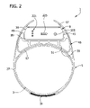
- FIG. 2 is a view similar to FIG. 1 showing the housing members in an expanded position for compressing the limb;
- FIG. 3 is a perspective view of the housing in its contracted condition
- FIG. 4 is a view similar to FIG. 3 but with the housing members exploded to show an actuator inside the housing;
- FIG. 4 a is an exemplary block diagram of a control system for controlling operation of one or more compression devices of this invention
- FIG. 5A is an end view of the housing in a contracted position with a portion of the side wall broken away to show a spring arrangement urging the housing toward its contracted condition;
- FIG. 5B is a view similar to FIG. 5A but showing the housing in an expanded condition
- FIG. 6 is a schematic view of the actuator and the housing members in their contracted position
- FIG. 7 is a view similar to FIG. 6 but showing the housing members in their expanded position
- FIG. 8 is a perspective view showing the compression device applied to a limb of a patient
- FIG. 9 is a view showing three compression devices of a system of this invention applied to the limb of a patient.
- FIG. 10 is a view showing a different embodiment of a compression system comprising an integrated compressive unit and three modules;
- FIG. 11 is a schematic view of an integrated compression unit and elements of an integrated control for controlling the operation of the modules of FIG. 10 ;
- FIG. 12 is an elevational view of a different embodiment of a compression device of this invention, comprising a bladder and a mechanical device for cyclically compressing the limb of a patient (shown in phantom), the mechanical device being shown in a contracted condition;
- FIG. 12A is a view similar to FIG. 12 showing the mechanical device in an expanded condition
- FIG. 13 is an elevational view of another embodiment of a compression device of this invention, comprising a bladder and a different mechanical device for cyclically compressing the limb of a patient (shown in phantom), the bladder being shown in a contracted condition;
- FIG. 13A is a view similar to FIG. 13 showing the bladder in an expanded condition
- FIG. 14 is an elevational view of still another embodiment of a compression device of this invention, comprising a bladder and a different mechanical device for cyclically compressing the limb of a patient (shown in phantom), the mechanical device being shown in a contracted condition; and
- FIG. 14A is a view similar to FIG. 14 showing the mechanical device in an expanded condition.
- the device is used for cyclically compressing the limb of a patient to improve blood flow in the limb.
- the limb may be a leg, foot or arm generically indicated at 3 in FIGS. 1 and 2 .
- the compression device comprises a compressive section, generally designated 5 , sized and shaped for extending generally circumferentially around a portion of the limb 3 for applying compressive pressure to the limb portion, the limb and limb portion both being numbered 3 in the figures.
- the compression device 1 also includes a housing, generally designated 9 , operatively connected to the compressive section 5 .
- the housing 9 includes first and second housing members indicated at 15 and 17 , respectively, movable relative to each other between a contracted position in which the housing has a first dimension D 1 ( FIG. 6 ) for relaxing pressure on the limb portion, and an expanded position in which the housing has a second dimension D 2 ( FIG. 7 ) greater than D 1 for compressing the limb portion.
- An actuator, generally indicated at 21 in FIG. 4 is provided in the housing 9 for cyclically moving the first and second housing members between their contracted ( FIG. 1 ) and expanded ( FIG. 2 ) positions.
- the compressive section 5 comprises a generally annular band 27 which encircles the limb 3 .
- the band material is preferably soft and non-abrasive to the skin and may include a slipping, non-compliant material at the interface of the band and the patient.
- the material is breathable and may have hydrophilic properties that help to improve patient comfort by creating a dry condition at the skin. (A dry skin condition tends to minimize chafing and abrasion, since the material is less likely to stick to the skin.)
- the band 27 may be of a non-woven PVC material which is substantially non-stretchable. As shown in FIGS.
- the band 27 comprises a band member (also designated 27 ) having opposite ends releasably secured together by means of a fastening device 31 (e.g., mating hooks and loops, releasable adhesives, snaps, buttons or other mechanisms) to provide circumferential adjustment to enable the band to fit limbs of different sizes.
- the band member 27 comprises a single elongate piece of material.
- the band member 27 can be formed in multiple pieces.
- the band member 27 can comprise a first piece releasably attached to one side of the second housing member 17 and a second piece releasably attached to an opposite side of the second housing member 17 .
- the band member 27 can be of varying length and width to accommodate limbs of differing sizes and shapes.
- one compression device 1 can have a thinner and shorter band member 27 to fit around the calf, while a second compression device can have a wider and longer band member 27 to fit around the thigh.
- the band 27 includes an interior layer 35 of material secured to the exterior layer of the band to form an interior pocket 39 which is sized and shaped for removably receiving the housing 9 containing the actuator 21 .
- the pocket has at least one open end for insertion of the housing into the pocket.
- a releasable closure such as a closure flap (not shown) can be provided for closing the open end of the pocket 39 to secure the housing in the pocket until such time as access is needed or desired.
- the housing 9 may be releasably secured in place in the pocket 39 by other means or combinations of means.
- an attaching member (not shown) is secured to an inside surface of the pocket 39 .
- the attaching member and housing 9 have mating detent components that securely, but releasably hold the housing in place.
- mating hook and loop fasteners on the housing 9 and on an interior surface of the pocket 39 or pocket closure (if used) can be used to releasably secure the housing 9 in the pocket.
- the housing 9 is snuggly fitted between semi-rigid holders secured within the pocket, creating a slip fit or interference fit. A release latch can be used to hold the housing 9 in place for additional sturdiness.
- the housing 9 may be removed from the pocket 39 for re-use with a different (fresh) band. Typically, the band 27 is discarded after a single use.
- a force-distributing device (generally designated 45 ) is interposed between the housing 9 and the limb 3 for distributing compressive forces applied by the device 1 more evenly across the limb.
- this device 45 comprises a cushion 49 received in the pocket 39 , the pocket being sized and shaped to hold both the housing 9 and the device 45 at a location between the housing 9 and the limb 3 of the patient.
- the cushion 49 comprises an extruded body of soft resilient rubber-like material having open cells separated by flexible walls 51 which absorb the compressive forces and distribute them more uniformly over the limb 3 .
- the cushion 49 has an upper surface 55 which conforms to the bottom (base member 15 ) of the housing 9 and which extends up on opposite sides of the housing to cradle it, and a lower surface 57 which is adapted to conform to the convex shape of a limb and which has rounded corner edges to minimize any pinching or abrasion of the skin.
- the cushion 49 comprises a sealed bladder filled with air or other suitable gas. (Various bladder embodiments are described later in this specification.)
- the cushion comprises a substantially solid body formed from a pliant gel-like material. Regardless of form, the force-distributing device 45 may be attached (e.g., adhered or otherwise fastened) to the housing 9 , or it may be unattached to the housing.
- the compression device may be used without a force-distributing device (e.g., device 45 ).
- the pocket 39 is preferably of a smaller size.
- the first housing member 15 comprises a base member (also designated 15 ) having a bottom wall 61 , opposite upstanding side walls 63 and opposite upstanding end walls 65 .
- the base member 15 is substantially rectangular, but other shapes can be used without departing from the scope of this invention.
- the interior space defined by the base member 15 is divided by a partition 67 into a first section or compartment 69 containing the actuator 21 and a second section or compartment 71 containing components for controlling the operation of the compression device (more on this later).
- the second housing member 17 comprises a cover member (also designated 17 ) having a substantially planar top wall 77 generally parallel to the bottom wall 61 of the base member 15 , opposite side walls 81 curving down from the top wall, and opposite end walls 83 extending down from the top wall.
- the top, side and end walls of the cover member 17 may have other shapes.
- the base and cover housing members 15 , 17 are fabricated from a suitable material, such as a flexible plastic or a rigid plastic having an outer coating of a more resilient material (e.g., an over-molded spongy or rubbery material).
- the parts may be molded as one-piece parts having a relatively thin-wall construction to reduce expense and weight.
- the base and cover members 15 , 17 of the housing are adapted to be moved by the actuator 21 from their stated contracted position to their stated expanded position.
- a contracted position the cover member 17 is spaced relatively close to the base member 15 and, in one embodiment, the bottom rim 87 of the cover member mates with the top rim 89 of the base member.
- the housing 9 In its contracted position ( FIG. 6 ), the housing 9 has the aforesaid dimension D 1 which is shown as representing the overall height of the housing in its contracted state.
- the cover member 17 of the housing is spaced farther away from the base member 15 so that the housing has the aforesaid dimension D 2 representing an increased overall height of the housing ( FIG. 2 ).
- the base and cover members 15 , 17 may have side walls which telescope relative to one another to provide the necessary dimensional change.
- the base and cover members 15 , 17 of the housing 9 are guided between their contracted and expanded positions by a number of pins 95 extending down from the rim 87 of the cover member through guide holes 99 in the rim 89 of the base member.
- the guide pins can extend up from the base member 15 through holes in the rim 87 of the cover member 17 .
- the base and cover members 15 , 17 are urged toward their contracted position by springs 103 surrounding the pins 99 , each spring reacting at one end against the underside of the rim 89 of the base member 15 and at its other end against a stop 105 on the pin.
- springs 103 are eliminated entirely, since the base and cover members 15 , 17 of the housing will move back toward their contracted position automatically as the actuator 21 moves back to a position corresponding to the contracted position of the housing.
- the actuator 21 is shown to be a mechanical actuator contained entirely within the housing 9 , i.e., within the space defined by the opposing housing members 15 , 17 .
- the actuator 21 of this particular embodiment is a non-pneumatic actuator, i.e., it does not include any components requiring the use of pressurized air or gas for operation.
- the actuator 21 includes a pair of cam shafts 115 having cams 121 mounted at one end thereof, a prime mover comprising a reversible electric motor 125 (e.g., a small DC motor) having an output shaft 127 , and a gear train, generally designated 131 , connecting the output shaft of the motor to the two cam shafts.
- a reversible electric motor 125 e.g., a small DC motor
- the gear train 131 comprises a pair of cam gears 135 rigidly affixed to respective cams 121 , a directional gear 141 in mesh with one of the two cam gears 135 , and a pinion gear 145 on the output shaft 127 of the motor 125 in mesh with the directional gear 141 and the other of the two cam gears 135 .
- Two additional cams 121 are mounted on the opposite ends of the cam shafts 115 , such that there are a total of four cams located for engaging the cover member 17 of the housing 9 at intervals spaced around the cover member to more evenly distribute the force applied by the actuator 21 over a greater area of the cover member.
- the number of cams 121 used can vary, four being shown for purposes of illustration only.
- the gears and cams are preferably (but not necessarily) of a suitable plastic for quiet operation.
- the arrangement shown in FIG. 4 is such that rotation of the motor output shaft 127 causes the two cam shafts 115 to rotate in opposite directions.
- the two cams 121 on each cam shaft 115 are shaped and contoured for contact with the bottom surfaces of the curved side walls 81 of the cover member 17 (or other downwardly facing surfaces of the cover member) such that rotation of the motor output shaft 127 in one direction causes the cams 121 to rotate, e.g., through a partial revolution, to increase the separation between the two housing members 15 , 17 against the urging of the springs 103 to expand the overall dimension of the housing 9 from D 1 ( FIG. 6 ) to the larger dimension indicated at D 2 in FIG. 7 .
- the motor 125 rotates the output shaft 127 in the reverse (opposite) direction to move the cams 121 back to their initial ( FIG. 6 ) position. This allows the two housing members to move back toward one another to contract the overall dimension of the housing 9 from D 2 to D 1 .
- the magnitudes of the distances D 1 and D 2 will vary depending on a variety of factors, such as the size and configuration of the base and cover members 15 , 17 of the housing, and the “throw” of the cams 121 as determined by the contour of their cam surfaces and the extent of rotary movement of the cam shafts 115 . In general, however, the system should be configured such that the housing members 15 , 17 expand a distance sufficient to apply the necessary compression to a limb and contract a distance sufficient to relieve such compression.
- the actuator 21 described above is only exemplary and that other actuators can be used for effecting relative movement between the housing members without departing from the scope of this invention.
- the actuator is non-pneumatic so that the compression device is entirely self-contained, i.e., all components for effecting cyclic compression are contained in a single garment which can be applied and removed as a unit from the patient. It is also preferred that the actuator be operable to rapidly expand and contract the housing 9 in an energy efficient manner.
- the compression device 1 further comprises a control system, generally designated 201 (see FIGS. 4 and 4A ), for controlling the operation of the device, including an on-off switch 205 positioned on the base member 15 of the housing 9 for convenient access and suitable electronics 211 located in the second compartment 71 of the base member 15 for controlling operation of the motor 125 .
- a power source comprising a battery 221 is also located in the second compartment 71 for supplying power to the motor 125 and other electrical components.
- the battery 221 can be an off-the-shelf item or custom designed, and it can be disposable or rechargeable.
- a battery charge indicator 225 is provided on the base member 15 of the housing 9 for indicating the remaining charge (useful life) of the battery 221 .
- FIG. 4A illustrates the control system 201 according to an embodiment of the invention. It will be understood that control system 201 is merely exemplary and that other control circuitry known to those skilled in the art can be used for controlling operation of device 1 generally and effectuating control of motor 125 particularly.
- the control system 201 desirably includes one or more devices 227 for indicating (either directly or indirectly) the pressure exerted by the compression device 1 on the limb 3 of a patient.
- this indicating device 227 senses a characteristic indicative of the actual pressure applied to the limb.
- the device 227 may comprise a suitable circuit for monitoring the amount of current and/or voltage to the electric motor 125 , which amount is proportional to the actual pressure applied to the limb.
- the pressure-indicating device may comprise one or more pressure sensors for sensing the pressure in one or more chambers in the cushion 49 (if a sealed bladder-like cushion is used), the sensed pressure being proportional to the actual pressure applied to the limb.
- the pressure-indicating device 227 may comprise one or more strain gauges on the band 27 , the tension in the band being indicative of the actual pressure on the limb. Other devices for indicating the pressure applied to the limb may be used.
- the control system 201 also includes a visual indicator 231 for indicating the operational status of the compression device 1 .
- FIG. 4 illustrates an example comprising an array of tri-color lamps 235 (LED's).
- the array indicates, among other things, the ON/OFF status of the compression device 1 , the status of any ongoing adjustment to a system setting (e.g., a pressure setting), the readiness of the actuator 21 to begin cycling, the status of communication with other compression devices which may be in use (described in more detail later), and an alarm condition.
- a system setting e.g., a pressure setting
- the status of communication with other compression devices which may be in use which may be in use (described in more detail later
- an alarm condition e.g., one lamp on (amber) may indicate that the power is on and that one or more setting adjustments are in progress.
- Two lights on (green) may indicate that the power is on and that all setting adjustments are complete.
- Three lights on (all green) may indicate that all adjustments are complete and that the compression device
- control system 201 further comprises a central processing unit (CPU) 237 , such as a microprocessor or the like for executing computer-implemented instructions in the form of software 237 a and/or firmware 237 b .
- the CPU 237 provides control signals to operate the actuator 21 of compression device 1 and to carry out a desired compression treatment regimen (as discussed below).
- the control signals from CPU 237 may provide distinct compression regimens, depending on the location of compression device 1 on the patient's limb 3 (e.g., attached to the calf at position B or the thigh at position C in FIG. 9 ). As shown in FIG.
- control system 201 communicates with its power source (e.g., battery 221 ) and visual indicator 231 via interconnection electronics 239 .
- the interconnection electronics 239 send control signals from CPU 237 to the compression device's prime mover (e.g., motor 125 ) over, for example, electrical or fiber optic lines.
- CPU 237 receives information from pressure-indicating devices 227 via interconnection electronics 239 over the same or similar lines.
- the electronics 211 of control system 201 also communicate with sensing elements 409 ( FIG. 11 ), one or more other compression devices (e.g., modules 321 in FIG. 9 ), external communications sources (e.g., RF or IR communications), and the like via electronics 239 .
- a processor such as CPU 237 may further execute computer-implemented instructions in the form of software 237 a and/or firmware 237 b to control voltage or speed of motor 125 to rotate its output shaft 127 for increasing the throw of the cams 121 , thereby increasing D 2 to increase the pressure during a compression therapy regimen.
- CPU 237 determines the treatment regimen and begins treating, as described above, by rotating motor 125 , which in turns adjusts the throw of the cams 121 for the correct pressure at the device based on its position on the limb (e.g., higher pressure may be desired on the ankle compared to the thigh).
- a typical use of the compression device 1 can be described as follows. Initially, the contracted housing 9 and force-distributing device 45 (if used) are inserted in the pocket 39 of the band 27 . The band is then applied to a portion of a limb 3 to be treated, as illustrated for example in FIG. 8 . As initially applied, the band 27 should be in a relatively relaxed state or condition applying little if any compressive force to the limb. After all setting adjustments have been made and the compression device is ready for operation, as indicated by the lamp array 235 , the control system 201 operates the actuator 21 to expand and contract the housing members 15 , 17 through a series of cycles, each cycle comprising a compress stage followed by a relax stage.
- the electric motor 125 is energized to rotate the cam shafts 115 in a first direction, which causes the two housing members 15 , 17 to move away from one another, thereby increasing the overall dimension of the housing from D 1 .
- the cover member 17 exerts a force in a direction away from the limb 3 to tension the band 27 and the base member 15 exerts a force in the opposite direction toward the leg.
- the force-distributing device 45 functions to distribute the compressive pressure more uniformly across the limb. As the cam shafts 115 continue to rotate, the pressure applied to the limb 3 increases.
- the control system 201 monitors the amount of applied pressure, as indicated for example by the amount of current and/or voltage supplied to the electric motor 125 . When a predetermined compressive pressure is reached, the control system de-energizes the motor to stop further rotation of the cam shafts. During this compression stage, the overall dimension of the housing increases from D 1 to D 2 .
- the control system 201 After a predetermined compressive pressure is applied to the limb 3 for a duration of time (compress interval), the control system 201 operates the motor 125 to rotate the cam shafts 115 and cams 121 thereon in the opposite direction to contract the housing members 15 , 17 and thus reduce the overall housing dimension from D 2 back to D 1 to relax the pressure on the limb.
- the relax pressure may range from zero to some pressure greater than zero but less than the compression pressure, as sensed by the current and/or voltage to the motor 125 or by some other suitable means.
- the relax pressure (if any) is maintained for a period of time (relax interval) sufficient to allow blood to return to the limb.
- the length of this time period may be fixed (e.g., sixty seconds) or it may vary depending on when a vascular refill condition is detected.
- the pressure sensing device of the control system 201 is used to detect the increase in limb size.
- the compressive pressure applied by the device may need to be adjusted.
- the control system 201 can make any necessary adjustment by varying the “throw” of the cams 121 until the pressure sensing device of the control system 201 indicates that the desired compressive pressure is being applied.
- the control system 201 simply operates the motor 125 to rotate its output shaft 127 through a greater number of degrees to increase the throw of the cams 121 and thus increase dimension D 2 of the housing 9 .
- the control system 201 operates the motor 125 to rotate its output shaft 127 through a shorter segment of rotation, thereby decreasing the throw of the cams 121 to decrease dimension D 2 .
- two or more compression devices can be used simultaneously on the limb or limbs of a patient.
- a plurality of compression devices 1 can be used on the same limb to cyclically compress different portions of the limb in a sequential manner.
- the compression devices can be applied to different limbs for compressing the limbs alternately or concurrently or in some other synchronized manner.
- the compression devices 1 A, 1 B and 1 C may operate completely independent of one another, or they may be under the control of a single integrated control system. If an integrated control system is used, it may be similar to the control system 201 described above for a single compression device but modified to include wireless (e.g., RF) transmitters and receivers and/or other components enabling communication between the multiple compression devices.
- wireless e.g., RF
- a first compression device 1 A is secured around the ankle for applying a first compressive pressure (e.g., 45 mmHg); a second compression device 1 B is secured around the calf for applying a second compressive pressure (e.g., 40 mmHg); and a third compression device 1 C is secured around the lower thigh of a patient for applying a third compressive pressure (e.g., 30 mmHg).
- the devices 1 A, 1 B, and 1 C can be physically interconnected, color-coded, or otherwise identified to indicate where they are to be placed and/or the different compressive pressures they will apply.
- the integrated control system operates the devices sequentially through a series of cycles, each of which includes a compress stage followed by a relax stage.
- Each compression device continues to expand until the proper pressure is reached, as sensed by the sensing device incorporated into the control system 201 of the compression device. Further expansion of the compression device is then stopped. There may be some overlap of the times during which the compression devices expand, but in general the compression applied by the devices should occur in a progressive manner to move the blood in the limb in a direction toward the heart.
- any further expansion of the compression devices 1 A, 1 B, 1 C is stopped, and the devices are contracted simultaneously to relax or release the pressure on respective portions of the limb.
- the relax stage preferably continues for an interval of time sufficient to allow blood to return to the limb, as discussed above.
- FIG. 10 shows another embodiment of a compression system of this invention, generally indicated at 301 .
- the system includes two or more compression devices, three such devices 303 , 305 , 307 being illustrated.
- the compression devices are similar to the compression device 1 described above except that the compressive sections are integrated into a single compressive unit 309 sized and shaped for extending generally circumferentially around a limb such as a leg.
- the term “integrated” means any configuration where the compressive sections are physically connected to one another.
- the unit 309 may comprise an elongate panel sized to encircle the limb and to be releasably secured in place by an appropriate number of fasteners along adjacent edges of the panel to form a sleeve around the limb.
- the compressive unit 309 may have other configurations.
- Pockets 315 are provided on the unit 309 for removably receiving respective “modules” 321 of the compression devices 303 , 305 , 307 .
- Each such module 321 includes a housing 9 , an actuator 21 and, preferably, a force-distributing device 45 , the construction and operation of which are described above. These modules 321 operate to apply compressive pressure to different portions of the limb.
- the modules 321 may be removably attached or otherwise removably connected to the unit 309 by means other than pockets.
- the compressive unit 309 is applied to the limb and the modules 321 are operatively connected to the unit, as by placing the modules in respective pockets of the unit.
- the modules are then operated to compress respective portions of the limb in a sequential manner, i.e., in a direction toward the heart. This direction is important so as not to cause injury to the patient.
- the modules 321 are removed from respective compressive sections of the unit 309 .
- the unit 309 is then typically discarded.
- the modules can be re-used with a different unit 309 holding multiple modules, or with one or more bands each holding only one module.
- the modules 321 can be positioned at different locations with respect to a limb during re-use, it is desirable to have an integrated control system which senses the location of the modules with respect to the limb, and which coordinates the operation of the modules after they have been placed in position so that proper sequential and gradient compression of the limb is achieved.
- the coordination of these modules should not interfere with the operation of other modules applied to a different limb of the same patient or with the operation of other modules on a limb or limbs or a different patient.
- FIG. 11 illustrates an exemplary integrated control system, generally designated 401 , for controlling the operation of two or more modules 321 when they are placed on the compressive unit 309 .
- the compressive unit 309 has three compressive sections or zones CZ 1 , CZ 2 and CZ 3 corresponding to different locations on the limb (e.g., ankle, calf and lower thigh), but it will be understood that the number of zones can vary.
- Each zone comprises a module sensing area 405 at a location where a module 321 is to be placed on the unit 309 . This location may correspond to the location of a pocket (e.g., like pocket 39 ) or other means for operatively and removably connecting the module to the unit 309 .
- the integrated control system 401 comprises location sensing devices on the unit 309 and on the modules 321 ( FIG. 10 ), for sensing the zone (e.g., CZ 1 , CZ 2 or CZ 3 ) in which each module is located when the modules are positioned on the compressive unit 309 .
- these location sensing devices comprise small sensing elements 409 in the module sensing areas 405 and cooperating sensing elements (not shown) on the modules 321 .
- these sensing elements 409 can be magnetic elements secured to the unit 309 for actuating magnet sensing elements on the modules to open or close circuits of the control system 401 .
- the sensing elements 409 can be optical elements on the unit 309 (e.g., areas of different colors or optical patterns) and optical sensing elements on the modules 321 for optically sensing, either reflectively or absorptively, the optical elements on the unit 309 .
- the sensing elements 409 can be electrical contacts on the unit 309 which mate with electrical contacts on the modules 321 when the modules are placed in position on the unit 309 .
- Other sensing elements can be used without departing from the scope of this invention.
- the integrated control system 401 also includes means for providing communication between the modules 321 .
- electrical or fiber-optic lines 421 may be embedded or otherwise secured to the unit.
- the modules When positioned on the unit 309 , the modules releasably connect with these lines 421 in a suitable manner (e.g., via quick-connect connectors) to provide the communication necessary for providing control information to and from the modules.
- the first (lower) and second (middle) sensing areas 405 are connected by a single pair of communication lines; the second and third (upper) sensing areas 405 are connected by two pairs of communication lines.
- Other line configurations are possible.
- communication between the modules may be by wireless RF or IR.
- the RF or IR communication signal is preferably directed only to the modules 321 on the unit 309 and not to other modules on different limbs or other patients.
- the control system 401 is able to coordinate the operation of the modules 321 , e.g., the pressure applied by each module to a respective limb portion, the timing of each compression cycle, and the detection, indication and/or correction of various parameters or errors (e.g., pressure, timing).
- the integrated control system 401 performs two functions. First, it senses the location of each module 321 with respect to the compression zone in which it is placed. Second, based on this sensed location, the system coordinates the operation of the modules 321 to achieve the desired sequential and gradient compression of the limb.
- the integrated control system 401 cooperates with control system 201 , such as shown in FIG. 4A , which may be part of each of the modules 321 .
- CPU 237 communicates via interconnection electronics 239 over one or more of the lines 421 .
- the software 239 a executed by CPU 237 may be modular such that control system 201 is capable of controlling operation of module 321 in any one of the sensing areas 405 .
- the CPU 239 is responsive to communications via line 421 and/or sensing elements 409 for identifying the relative position of the associated module 321 and providing control signals as a function of the identified position.
- Each control system 201 associated with one of the modules 321 operates independently to effectuate a compression regimen in one location on compression unit 309 , but its operation is coordinated with that of the control systems 201 associated with other modules 321 .
- the control signals from each CPU 237 may provide distinct compression regimens, depending on the location of compression device 1 on the patient's limb 3 (e.g., attached to the calf at position B or the thigh at position C in FIG. 9 ). For example, when control system 201 identifies one or more compression devices 1 A, 1 B or 1 C attached to the patient's limb 3 , as in FIG.
- software 237 a causes the control systems 201 to place their associated modules 321 in a standby mode until the user activates one of the modules. Once activated, CPU 237 executes software 237 a to determine the treatment regimen for the respective position of the associated module 321 and begins treatment.
- one control system 201 functions as a master controller for controlling operation of all of the modules 321 connected thereto.
- the control system 201 associated with one module 321 is responsive to the control system associated with another module 321 as a function of the relative positions of the modules on the patient's limb 3 .
- the integrated control system 401 comprises the control systems 201 associated with the compression devices 1 of modules 321 operating cooperatively.
- FIG. 12 illustrates an alternate embodiment of a compression device of this invention, generally designated 501 .
- the force-distributing device comprises one or more bladders 505 (only one being shown) filled with air or other suitable gas.
- the combination of the bladder(s) 505 , housing 9 and actuator 21 form a module 509 received (e.g., removably received) in the pocket 39 of the compressive section 5 .
- the module 509 is adapted for cyclic expansion and contraction in opposite generally radial directions 511 with respect to the limb portion 3 between a contracted condition ( FIG. 12 ) in which the module has a first dimension 551 for relaxing pressure on the limb portion, and an expanded condition ( FIG. 12A ) in which the module has a second dimension 553 greater than the first dimension for compressing the limb portion.
- the bladder 505 provides additional pressure and size adjustment when compressive treatment is provided to the patient.
- the bladder 505 is a sensing bladder for sensing a characteristic of compression therapy on a patient.
- the bladder 505 has a sensing device 521 in communication with the contents of the bladder for sensing, for example, the pressure of the contents of the bladder, and for outputting a signal indicative of that characteristic to the control system 201 . Placing the sensor in-situ with the bladder medium provides for greater accuracy and control of the compression afforded during treatment.
- the bladder pressure directly impacts blood flow, in that, a lower pressure distributes less force from the mechanical device to the patient limbs, and likewise a higher pressure distributes a greater amount of the force from the mechanical device to the patient's limb.
- the ability to adjust the bladder pressure with precision allows the patient to tailor treatment to their comfort level.
- a patient wearing the device can adjust the nominal pressure, independent of computer instruction operating a therapy regime, as described below in the operation of the device.
- Other sensing devices for sensing other characteristics of the compression therapy are contemplated.
- the sensor may be a sensor, in a thin layer composite, between the bladder and the leg for sensing a condition of the patient (e.g., temperature, pulse, blood flow, oxygen level).
- the bladder has a pneumatic port 513 and a suitable valve mechanism (not shown) for inflation of the bladder by a pump 515 .
- this pump 515 is integral with the compression device 501 and is mounted inside or adjacent the base member 15 of the housing 9 for communication with the port 513 .
- the pump 515 is a small pneumatic pump, such as a miniature battery-operated air compressor, which consumes a relatively small amount of power.
- the power is provided by the battery 221 or a separate power source in the housing 9 .
- the pump used to inflate the bladder can be non-integral with the compression device 501 .
- the pump can be a hand pump manually operated by the patient or caregiver.
- a suitable transducer 521 (e.g., pressure sensor) is provided for sensing pressure of the air (or other gas) in the bladder 505 .
- the bladder 505 can be sized to minimize the distance (e.g., D 2 minus D 1 in FIGS. 6 and 7 ) by which the housing parts 15 , 17 must expand and contract to effect the necessary cyclic compression.
- the size of various components of the actuator 21 e.g., motor 125 , cams 121 , gears 135 , 141 , 145 ) can be decreased to reduce cost.
- one or more of the compression devices 501 are applied to the limb 3 to be treated, as described in the previous embodiments.
- a nominal pressure is maintained in the bladder(s) 505 to provide for therapy adjustment, to provide a static baseline pressure, and to distribute the compressive forces applied by the compression device 501 evenly about the surface of the leg or limb of a patient.
- the transducer 521 provides feedback to the controller (e.g., CPU 237 in FIG. 4 a ) for application of proper therapy to the limb.
- the pressure in the bladder(s) 505 is maintained by the pump 515 .
- a pressure relief valve or passively activated check valve can be installed to maintain the pressure in the bladder(s) 505 at a pressure no greater than a predetermined pressure.
- the compression device 501 cyclically compresses both the limb and the bladder(s) 505 .
- This action is monitored by the transducer 521 which provides feedback to the controller to monitor and adjust the tension in band 27 .
- the aforementioned small nominal pressure is maintained in the bladder 505 during the relax stage of each compression cycle. This pressure is much less than in prior art systems, such as found in U.S. Pat. No. 4,253,449 (Arians et al.) owned by Tyco Healthcare Group LP.
- the pneumatic port 513 of the bladder 505 is closed by a suitable valve mechanism (not shown) or other means to capture the small nominal pressure in the bladder.
- a suitable valve mechanism not shown
- the pressure transducer 521 monitors this change in pressure and the peak pressure value is fed into a feedback algorithm executed in one of the software and/or firmware modules 237 a , 237 b of FIG. 4 a .
- the algorithm functions to compare the peak pressure value to a predetermined (selected) peak value or set point corresponding to the desired maximum pressure to be applied to the limb during the compress stage of each cycle.
- the nominal pressure in the bladder 505 is adjusted downward by venting an appropriate amount of air (or other gas) from the bladder. Conversely, if the sensed peak pressure is lower than the predetermined set point, then the nominal pressure in the bladder 505 is adjusted upward by delivering additional air (or other gas) to the bladder(s). This adjustment process continues for subsequent cycles until the sensed peak pressure value substantially matches the predetermined maximum pressure set point.
- this compression device 501 In the case of an edematous patient, the level of swelling in a limb or limbs can change over time.
- An advantage of this compression device 501 is that the pressure in the bladder(s) 505 , as sensed by the pressure transducer 521 , can be adjusted to reduce or increase the volume contained within the compressive band 27 in a manner which is inversely proportional to the amount of edema change. For example, if the compression device 501 is set to apply a predetermined compressive pressure of 45 mmHg during the compress interval, but the pressure transducer 521 senses a bladder pressure of 50 mmHg due to increased edema, the control system 201 will automatically reduce the pressure in the bladder(s) 505 to compensate for the increased swelling. As a result, blood flow to the swollen limb is not unduly restricted.
- the compression device 501 using one or more bladders 505 is also capable of measuring vascular refill time (VRT).
- VRT measurement is an air plethysmographic technique that determines when the veins of a limb have substantially completely refilled with blood after the compression stage of a compression cycle. See, for example, the VRT measurement described in U.S. Pat. No. 6,231,532 to Watson et al., the entire content of which is incorporated by reference herein. This VRT technique is used to minimize the amount of time that blood remains stagnant in the veins.
- the bladder pressure is sampled at one-second intervals and the pressure is monitored by using a moving or “rolling” 10-second window of time in which the oldest sample value is dropped from the window and a new sample value is added every second.
- a predetermined value e.g., about 0.3 mmHg
- the vascular refill time is then determined (T end minus T start ) and, if necessary, an appropriate adjustment to the relax interval of the compression cycle is then made.
- the “default” relax interval is 60 seconds. If the measured VRT is greater than 60 seconds, then the relax interval remains at 60 seconds. If the measured VRT is between 20 and 60 seconds, the relax interval is re-set to the measured VRT. If the measured VRT is less than 20 seconds, then the relax interval is re-set to a minimum time of 20 seconds, for example.
- the minimum relax interval (e.g., 20 seconds) should be sufficient to insure that the limb has substantially refilled with blood before initiation of the compress stage of the next cycle.
- the minimum relax interval may also be established by adding a predetermined safety factor (e.g., 5 seconds) to the measured VRT.
- the VRT measurement may be disregarded.
- such circumstances might include a situation where the standard deviation of the pressure values in the sample window exceed a predetermined maximum standard deviation, indicating that the VRT measurement is erroneous; or a situation where the sensed pressure in the bladder(s) 505 falls below a predetermined minimum value (e.g., 2 mmHg) during the measurement process, indicating a possible leak in the system; or a situation where the sensed pressure in the bladder(s) 505 exceeds a predetermined value (e.g., 20 mmHg) during the measurement process.
- the VRT measurement is disregarded, and the relax interval of the prior cycle continues to be used.
- more than one compression device 501 can be used to sequentially compress different portions of the same limb (e.g., one leg) or different limbs (e.g., two legs). If more than one device 501 is used, the VRT is determined separately for each limb portion being compressed. Preferably, the longest of the measured vascular refill times is then used as the new relax interval for all of the compression devices.
- the VRT measurements for the compression devices are made (i.e., started and stopped) independent of one another. Preferably, however, any adjustment to the relax interval of the compression devices is not made until after the VRT measurements have been completed for all devices.
- control system 201 of the compression system 501 may provide an audible and/or visual error alarm for one or more of the following error conditions: high pressure error, including a sensed pressure greater than a set maximum pressure; low pressure error, including a sensed pressure less than a set minimum pressure (e.g., also detecting the absence of bands or sleeves); system pressure error, including a pressure sensed during a compress stage and/or relax stage of a compression cycle outside of desired parameters; valve error; software error; pump error; vent and deflation error; battery error; and temperature error, including temperatures detected outside of specified environmental conditions.
- high pressure error including a sensed pressure greater than a set maximum pressure
- low pressure error including a sensed pressure less than a set minimum pressure (e.g., also detecting the absence of bands or sleeves)
- system pressure error including a pressure sensed during a compress stage and/or relax stage of a compression cycle outside of desired parameters
- valve error software error
- pump error vent and deflation error
- battery error including temperatures detected outside of specified environmental
- the compression device 501 can be modified to include one or more temperature sensors to provide the latter feature.
- An alarm system of the type described advantageously enhances the safety of the patient during vascular therapy.
- the visual indicator 231 or other means may flash error signals, sound a continuous alarm, or otherwise indicate an alarm situation.
- the control system 201 may be responsive to an alarm condition to deflate the bladder(s) 505 and cease further operation of the compression device 501 .
- FIG. 13 illustrates a third embodiment of a compression device of this invention, generally designated 601 .
- This embodiment is similar to the previous embodiment 501 in that it comprises a compressive section 607 adapted to extend around a portion 609 of a limb, at least one pneumatic bladder 615 , and a non-pneumatic mechanical device, generally designated 619 .
- the bladder(s) 615 and mechanical device 619 combine to form a module 621 which is received (e.g., removably received) in a pocket 623 on the compressive section 607 .
- the module 621 may be operatively connected to the compressive section 607 in other ways.
- the module 621 is adapted for cyclic expansion and contraction in opposite generally radial directions 624 with respect to the limb portion 609 between a contracted condition ( FIG. 13 ) in which the module has a first dimension 651 for relaxing pressure on the limb portion, and an expanded condition ( FIG. 13A ) in which the module has a second dimension 653 greater than the first dimension 651 for compressing the limb portion.
- the compressive section 607 comprises a band member 635 having opposite ends which are releasably connected by a suitable fastening device 637 (e.g., similar to 31 in the first embodiment) to form an annular band around the limb.
- the compressive section 607 may have other configurations.
- the mechanical device 619 is non-pneumatic in the sense that it does not include pneumatic components requiring or involving the use of pressurized air or other gas.
- the device 619 includes an inner platen 625 seated on the bladder 615 , an opposing outer platen 627 , and one or more springs 631 between the platens urging the platens away from one another.
- the springs 631 of the mechanical device 619 generate a force tending to move the outer platen 627 in a direction away from the limb to expand the module 621 and thereby tension (tighten) the band member 635 around the limb.
- the limb is cyclically compressed by varying the pressure in the bladder(s) 615 to expand and contract the bladder.
- the pressure may be varied by cycling the operation of a small pneumatic pump 641 , such as a miniature battery-operated compressor mounted on or adjacent the inner platen 625 .
- the pump 641 communicates with a pneumatic port 645 on the bladder(s).
- a pressure sensor (not shown) monitors the pressure in the bladder(s) 615 .
- a pressure relief valve or passively activated check valve can be installed to maintain the pressure in the bladder(s) 615 at a pressure no greater than a predetermined pressure.
- the pump 641 inflates the bladder(s) 615 which causes the module 621 to expand to compress the limb portion 609 to a predetermined pressure during a compress stage of the compression cycle.
- the pump 641 deflates the bladder(s) 615 to a predetermined pressure after an appropriate compress interval has ended. This causes the module 621 to contract for relieving the pressure on the limb during the relax stage of the compression cycle.
- the module 621 expands and contracts in opposing generally radial (not circumferential) directions relative to the limb portion 609 .
- FIG. 14 illustrates a fourth embodiment of a compression device of this invention, generally designated 701 .
- This embodiment is similar to the compression device 501 previously described in that it comprises a compressive section 707 adapted to extend around a portion 709 of a limb, at least one pneumatic bladder 715 , and a non-pneumatic mechanical device, generally designated 719 .
- the bladder(s) 715 and mechanical device 719 combine to form a module 721 which is received (e.g., removably received) in a pocket 723 on the compressive section 707 .
- the module 721 may be operatively connected to the compressive section 707 in other ways.
- the module 721 is adapted for cyclic expansion and contraction in opposite generally radial directions 724 with respect to the limb portion 709 between a contracted condition in which the module has a first dimension 761 for relaxing pressure on the limb portion, and an expanded condition ( FIG. 14A ) in which the module has a second dimension 763 greater than the first dimension for compressing the limb portion.
- the compressive section 707 comprises a band member 735 having opposite ends which are releasably connected by a suitable fastening device 737 (e.g., similar to 31 in the first embodiment) to form an annular band around the limb.
- the compressive section 707 may have other configurations.
- the bladder(s) 715 is positioned between the limb portion 709 and the mechanical device 719 .
- the bladder(s) has a pneumatic port 725 for inflation and deflation of the bladder, as by a hand pump manually operated by the patient or caregiver.
- the mechanical device 719 is non-pneumatic in the sense that it does not include pneumatic components requiring or involving the use of pressurized air or other gas.
- the device 719 includes a housing comprising a base housing member 727 seated on the bladder 715 , an opposing cover housing member 729 , and an actuator 731 inside the housing for moving the housing members toward and away from one another, as described in regard to compression device 501 .
- the actuator 731 comprises one or more cams 741 movable between a first position (shown in solid lines in FIG. 14 ) in which the housing members 727 , 729 are relatively closely spaced in a contracted position or condition, and a second position (shown in phantom lines in FIG.
- the cam 741 is rotated between its first and second positions by a prime mover (e.g., a small DC motor, not shown) having an output 747 which is connected to the cam 741 by a gear train 751 or other suitable means.
- the cam(s) 741 , prime mover and gear train 751 are located inside the base housing member 727 , similar to the compression devices 1 , 501 described above.
- the “throw” of the cam(s) 741 may be adjustable, as described previously. Alternatively, it may be non-adjustable to reduce cost.
- a pressure sensor (not shown) monitors the pressure in the bladder(s) 715 .
- a pressure relief valve or passively activated check valve can be installed to maintain the pressure in the bladder(s) 715 at a pressure no greater than a predetermined pressure.
- the bladder(s) 715 is inflated to a suitable pressure using the pneumatic port 725 .
- the actuator 731 is then energized to move the base and cover members 727 , 729 toward and away from one another to expand and contract the module 721 to conduct successive compression cycles on the limb portion 709 .
- the module 721 expands and contracts in opposite generally radial (not circumferential) directions relative to the limb portion 709 .
- the pressure in the bladder(s) 715 can be adjusted, if necessary.
- the cost of the compression device can be reduced to a point where the entire device can be discarded after a single use.
- a disposable device has several benefits. First, it is more hygienic for the patient population. Further, the cost of reprocessing the device or components of the device is eliminated. Also, due to the reduced size and weight of the various components, the device is more portable.
- the bladder embodiments described above are, for the most part, “self-contained”, meaning that all components of the compression apparatus and the control are located on the garment worn by the patient.
Landscapes
- Health & Medical Sciences (AREA)
- Life Sciences & Earth Sciences (AREA)
- General Health & Medical Sciences (AREA)
- Veterinary Medicine (AREA)
- Public Health (AREA)
- Animal Behavior & Ethology (AREA)
- Surgery (AREA)
- Molecular Biology (AREA)
- Engineering & Computer Science (AREA)
- Medical Informatics (AREA)
- Heart & Thoracic Surgery (AREA)
- Biomedical Technology (AREA)
- Biophysics (AREA)
- Pain & Pain Management (AREA)
- Physical Education & Sports Medicine (AREA)
- Epidemiology (AREA)
- Physics & Mathematics (AREA)
- Rehabilitation Therapy (AREA)
- Pathology (AREA)
- Nuclear Medicine, Radiotherapy & Molecular Imaging (AREA)
- Vascular Medicine (AREA)
- Reproductive Health (AREA)
- Massaging Devices (AREA)
- Percussion Or Vibration Massage (AREA)
Priority Applications (16)
| Application Number | Priority Date | Filing Date | Title |
|---|---|---|---|
| US11/533,524 US7618384B2 (en) | 2006-09-20 | 2006-09-20 | Compression device, system and method of use |
| CA2747847A CA2747847A1 (en) | 2006-09-20 | 2007-08-22 | Compression device, system and method of use |
| CA2598363A CA2598363C (en) | 2006-09-20 | 2007-08-22 | Compression device, system and method of use |
| IL211621A IL211621A0 (en) | 2006-09-20 | 2007-08-29 | Compression device, system and method of use |
| IL223474A IL223474A0 (en) | 2006-09-20 | 2007-08-29 | Compression device system and method of use |
| IL185588A IL185588A (en) | 2006-09-20 | 2007-08-29 | Compression device and system for improving blood flow in the limb |
| AU2007216669A AU2007216669B2 (en) | 2006-09-20 | 2007-09-06 | Compression device, system and method of use |
| EP07115927A EP1902701A3 (en) | 2006-09-20 | 2007-09-07 | Compression device, system and metod of use |
| BRPI0703662-0A BRPI0703662A (pt) | 2006-09-20 | 2007-09-20 | dispositivo de compressão, sistema e método de uso do mesmo |
| JP2007243566A JP4603026B2 (ja) | 2006-09-20 | 2007-09-20 | 圧迫装置、システム、及び使用方法 |
| US12/027,844 US20080125684A1 (en) | 2006-09-20 | 2008-02-07 | Disposable band for a compression device |
| US12/563,207 US20100010405A1 (en) | 2006-09-20 | 2009-09-21 | Self-contained compression device with pneumatic bladder and method |
| US12/563,215 US20100010406A1 (en) | 2006-09-20 | 2009-09-21 | Self-contained compression device with cam-movable housing members and method |
| US12/563,210 US20100010404A1 (en) | 2006-09-20 | 2009-09-21 | Self-contained compression devicewith spring-biased housing members and method |
| IL223475A IL223475A0 (en) | 2006-09-20 | 2012-12-06 | Compression device, system and method of use |
| IL223473A IL223473A0 (en) | 2006-09-20 | 2012-12-06 | Compression device , system for improving blood flow in the limb |
Applications Claiming Priority (1)
| Application Number | Priority Date | Filing Date | Title |
|---|---|---|---|
| US11/533,524 US7618384B2 (en) | 2006-09-20 | 2006-09-20 | Compression device, system and method of use |
Related Child Applications (4)
| Application Number | Title | Priority Date | Filing Date |
|---|---|---|---|
| US12/027,844 Division US20080125684A1 (en) | 2006-09-20 | 2008-02-07 | Disposable band for a compression device |
| US12/563,215 Division US20100010406A1 (en) | 2006-09-20 | 2009-09-21 | Self-contained compression device with cam-movable housing members and method |
| US12/563,210 Division US20100010404A1 (en) | 2006-09-20 | 2009-09-21 | Self-contained compression devicewith spring-biased housing members and method |
| US12/563,207 Division US20100010405A1 (en) | 2006-09-20 | 2009-09-21 | Self-contained compression device with pneumatic bladder and method |
Publications (2)
| Publication Number | Publication Date |
|---|---|
| US20080071202A1 US20080071202A1 (en) | 2008-03-20 |
| US7618384B2 true US7618384B2 (en) | 2009-11-17 |
Family
ID=38780824
Family Applications (5)
| Application Number | Title | Priority Date | Filing Date |
|---|---|---|---|
| US11/533,524 Active 2026-10-14 US7618384B2 (en) | 2006-09-20 | 2006-09-20 | Compression device, system and method of use |
| US12/027,844 Abandoned US20080125684A1 (en) | 2006-09-20 | 2008-02-07 | Disposable band for a compression device |
| US12/563,210 Abandoned US20100010404A1 (en) | 2006-09-20 | 2009-09-21 | Self-contained compression devicewith spring-biased housing members and method |
| US12/563,215 Abandoned US20100010406A1 (en) | 2006-09-20 | 2009-09-21 | Self-contained compression device with cam-movable housing members and method |
| US12/563,207 Abandoned US20100010405A1 (en) | 2006-09-20 | 2009-09-21 | Self-contained compression device with pneumatic bladder and method |
Family Applications After (4)
| Application Number | Title | Priority Date | Filing Date |
|---|---|---|---|
| US12/027,844 Abandoned US20080125684A1 (en) | 2006-09-20 | 2008-02-07 | Disposable band for a compression device |
| US12/563,210 Abandoned US20100010404A1 (en) | 2006-09-20 | 2009-09-21 | Self-contained compression devicewith spring-biased housing members and method |
| US12/563,215 Abandoned US20100010406A1 (en) | 2006-09-20 | 2009-09-21 | Self-contained compression device with cam-movable housing members and method |
| US12/563,207 Abandoned US20100010405A1 (en) | 2006-09-20 | 2009-09-21 | Self-contained compression device with pneumatic bladder and method |
Country Status (7)
| Country | Link |
|---|---|
| US (5) | US7618384B2 (pt) |
| EP (1) | EP1902701A3 (pt) |
| JP (1) | JP4603026B2 (pt) |
| AU (1) | AU2007216669B2 (pt) |
| BR (1) | BRPI0703662A (pt) |
| CA (2) | CA2598363C (pt) |
| IL (5) | IL185588A (pt) |
Cited By (56)
| Publication number | Priority date | Publication date | Assignee | Title |
|---|---|---|---|---|
| US20050107725A1 (en) * | 2003-03-27 | 2005-05-19 | Wild David G. | Compression device for the limb |
| US20070038167A1 (en) * | 2005-06-08 | 2007-02-15 | Bristol-Myers Squibb Company | Compression device for the foot |
| US20070249976A1 (en) * | 2006-01-24 | 2007-10-25 | Bristol-Myers Squibb Company | Proximity detection apparatus |
| US20080319359A1 (en) * | 2007-06-20 | 2008-12-25 | Remo Moomiaie-Qajar | Portable compression device |
| US20100130889A1 (en) * | 2007-01-24 | 2010-05-27 | Convatec Technologies Inc. | Elastomeric particle having an electrically conducting surface, a pressure sensor comprising said particles, a method for producing said sensor and a sensor system comprising said sensors |
| US20100268130A1 (en) * | 2007-10-09 | 2010-10-21 | Khan Sitara R | Blood clot prevention device |
| US20110009795A1 (en) * | 2009-07-10 | 2011-01-13 | Tyco Healthcare Group Lp | Hybrid compression garmet |
| US20110066091A1 (en) * | 2004-10-11 | 2011-03-17 | Convatec Technologies Inc. | Electro active compression bandage |
| US20110066093A1 (en) * | 2009-09-15 | 2011-03-17 | Tyco Healthcare Group Lp | Portable, self-contained compression device |
| US20110224589A1 (en) * | 2010-03-09 | 2011-09-15 | Tyco Healthcare Group Lp | Venous Augmentation System |
| US20110275967A1 (en) * | 2010-05-05 | 2011-11-10 | Wei-Ting Lin | Massaging device |
| US20110319787A1 (en) * | 2009-01-13 | 2011-12-29 | Laboratoires Urgo | Interface pressure measurement system |
| US20120265111A1 (en) * | 2009-10-19 | 2012-10-18 | Storz Medical Ag | Shockwave apparatus having a pneumatic drive |
| US8597215B2 (en) | 2007-04-09 | 2013-12-03 | Covidien Lp | Compression device with structural support features |
| US8622942B2 (en) | 2007-04-09 | 2014-01-07 | Covidien Lp | Method of making compression sleeve with structural support features |
| US8632840B2 (en) | 2008-09-30 | 2014-01-21 | Covidien Lp | Compression device with wear area |
| US8721575B2 (en) | 2007-04-09 | 2014-05-13 | Covidien Lp | Compression device with s-shaped bladder |
| US8740828B2 (en) | 2007-04-09 | 2014-06-03 | Covidien Lp | Compression device with improved moisture evaporation |
| US8764689B2 (en) | 2006-01-13 | 2014-07-01 | Swelling Solutions, Inc. | Device, system and method for compression treatment of a body part |
| US8801643B2 (en) | 2010-02-12 | 2014-08-12 | Covidien Lp | Compression garment assembly |
| US20150119926A1 (en) * | 2013-10-25 | 2015-04-30 | Medtronic Vascular, Inc. | Tissue Compression Device with Pressure Indicator |
| US9084713B2 (en) | 2007-04-09 | 2015-07-21 | Covidien Lp | Compression device having cooling capability |
| USD737327S1 (en) | 2013-06-17 | 2015-08-25 | Covidien Lp | Display screen with a transitional leak detection icon |
| US9114052B2 (en) | 2007-04-09 | 2015-08-25 | Covidien Lp | Compression device with strategic weld construction |
| USD737328S1 (en) | 2013-06-17 | 2015-08-25 | Covidien Lp | Display screen with graphical user interface for venous refill detection |
| USD737855S1 (en) | 2013-06-17 | 2015-09-01 | Covidien Lp | Display screen with a transitional venous refill detection icon |
| CN105012122A (zh) * | 2015-06-24 | 2015-11-04 | 孟红琳 | 自吸移动式按摩装置 |
| US9205021B2 (en) | 2012-06-18 | 2015-12-08 | Covidien Lp | Compression system with vent cooling feature |
| US20160058654A1 (en) * | 2014-08-27 | 2016-03-03 | Covidien Lp | Compression Garment Inflation |
| US20160095782A1 (en) * | 2014-10-07 | 2016-04-07 | International Biophysics Corporation | Self-contained portable positionable oscillating motor array including disposable and/or recyclable portions |
| US20160132023A1 (en) * | 2014-11-07 | 2016-05-12 | Lg Electronics Inc. | Wearable watch type mobile terminal |
| US9364037B2 (en) | 2005-07-26 | 2016-06-14 | Covidien Ag | Limited durability fastening for a garment |
| USD760728S1 (en) | 2013-06-17 | 2016-07-05 | Covidien Lp | Display screen with graphical user interface for patient use meter reset |
| US9387146B2 (en) | 2007-04-09 | 2016-07-12 | Covidien Lp | Compression device having weld seam moisture transfer |
| US9433532B2 (en) | 2008-09-30 | 2016-09-06 | Covidien Lp | Tubeless compression device |
| US20160255944A1 (en) * | 2015-03-08 | 2016-09-08 | Apple Inc. | Dynamic Fit Adjustment for Wearable Electronic Devices |
| USD774057S1 (en) | 2013-06-17 | 2016-12-13 | Covidien Lp | Display screen with a graphical user interface for compliance monitoring |
| US9549869B2 (en) | 2012-06-29 | 2017-01-24 | Hill-Rom Canado Respiratory Ltd. | Wearable thorax percussion device |
| US9717641B2 (en) * | 2015-02-13 | 2017-08-01 | Albert Ky | Portable leg deep vein massager and propulsor |
| WO2017134663A1 (en) * | 2016-02-02 | 2017-08-10 | Nashif Saeed | Device for applying pressure on a body part |
| US9744097B2 (en) | 2012-06-29 | 2017-08-29 | Hill-Rom Services Pte. Ltd. | Wearable thorax percussion device |
| US9901510B2 (en) | 2013-12-09 | 2018-02-27 | Brett Gene Smith | Portable apparatus for providing chest therapy |
| US10016203B2 (en) | 2004-06-08 | 2018-07-10 | Composite Resources, Inc. | Tourniquet and method of use |
| US10076462B2 (en) | 2016-04-27 | 2018-09-18 | Radial Medical, Inc. | Adaptive compression therapy systems and methods |
| WO2019032325A1 (en) | 2017-08-07 | 2019-02-14 | Shah Bhavya Ramesh | DEVICE, SYSTEMS AND METHODS FOR PREVENTING DEEP VENOUS THROMBOSIS |
| US10314531B2 (en) | 2010-09-30 | 2019-06-11 | Kpr U.S., Llc | Monitoring compliance using venous refill detection |
| US10342730B2 (en) | 2011-09-29 | 2019-07-09 | Kpr U.S., Llc | Compression garment having sealable bladder pocket |
| US10959912B2 (en) | 2013-12-09 | 2021-03-30 | Exemplar Medical LLC | Portable apparatus for providing chest therapy |
| US20210153748A1 (en) * | 2015-10-07 | 2021-05-27 | Fiomet Ventures, Inc. | Advanced Compression Garments and Systems |
| US11077011B2 (en) | 2015-10-09 | 2021-08-03 | Kpr U.S., Llc | Compression garment compliance |
| US20220202145A1 (en) * | 2020-12-29 | 2022-06-30 | Shanghai Tianma Am-Oled Co.,Ltd. | Wristband and wristwatch |
| US11471116B2 (en) | 2006-01-24 | 2022-10-18 | Swelling Solutions, Inc. | Control unit assembly |
| US11471366B2 (en) | 2016-08-22 | 2022-10-18 | Hill-Rom Services Pte. Ltd. | Percussion therapy apparatus and methods thereof |
| US12076483B2 (en) | 2013-12-09 | 2024-09-03 | Exemplar Medical LLC | Portable apparatus for providing chest therapy |
| US20250205087A1 (en) * | 2023-12-20 | 2025-06-26 | Illinois Tool Works Inc. | Welding headgear with head strap tightness feedback and limiting |
| US12594217B2 (en) | 2021-05-24 | 2026-04-07 | Tactile Systems Technology, Inc. | Self-contained portable positionable oscillating motor array with strap tension sensing elements |
Families Citing this family (68)
| Publication number | Priority date | Publication date | Assignee | Title |
|---|---|---|---|---|
| US7618384B2 (en) * | 2006-09-20 | 2009-11-17 | Tyco Healthcare Group Lp | Compression device, system and method of use |
| US8597194B2 (en) * | 2006-10-26 | 2013-12-03 | Medical Compression Systems (Dbn) Ltd. | System and method for deep vein thrombosis prevention and diagnosis |
| GB2464440B (en) * | 2007-07-23 | 2012-04-11 | Eyal Avramovich | Massager |
| CN104586624B (zh) * | 2008-07-08 | 2018-02-16 | 阿维科斯有限公司 | 脚压迫系统 |
| US9439828B2 (en) | 2008-07-08 | 2016-09-13 | Avex, L.L.C. | Foot compression system |
| CA2731555C (en) * | 2008-08-03 | 2016-11-01 | Lunguard Ltd. | Enteral feeding device, system comprising it, methods and uses thereof |
| KR101087657B1 (ko) | 2009-05-14 | 2011-11-30 | 강기석 | 장의 꿈틀운동을 구현하기 위한 연동장치 |
| WO2010146593A1 (en) * | 2009-06-19 | 2010-12-23 | Gbveintech Ltd. | Device and method for applying pressure to a body limb |
| CN102548490B (zh) * | 2009-07-31 | 2015-05-13 | 贝鲁斯医疗器材集团公司 | 压迫止血装置 |
| US9168045B2 (en) * | 2009-09-11 | 2015-10-27 | Tbi Innovations, Llc | Device to reduce SLOSH energy absorption and its damaging effects through the reduction of the flow of one or more outflow vessels of the cranium |
| US10004515B2 (en) | 2009-09-11 | 2018-06-26 | Tbi Innovations, Llc | Methods and devices to reduce damaging effects of concussive or blast forces on a subject |
| US9173660B2 (en) * | 2009-09-11 | 2015-11-03 | Tbi Innovations, Llc | Methods and devices to reduce the likelihood of injury from concussive or blast forces |
| US11696766B2 (en) | 2009-09-11 | 2023-07-11 | Tbi Innovations, Llc | Methods and devices to reduce damaging effects of concussive or blast forces on a subject |
| US8394042B1 (en) * | 2009-09-17 | 2013-03-12 | Mansoor Mirza | Portable sequential compression device |
| US8652079B2 (en) | 2010-04-02 | 2014-02-18 | Covidien Lp | Compression garment having an extension |
| SE535901C2 (sv) * | 2010-06-07 | 2013-02-12 | St Jude Medical Systems Ab | Femoralt kompressionssystem och metod för att åstadkomma kompression med det femorala kompressionssystemet |
| CN103068346B (zh) * | 2010-06-11 | 2016-03-02 | W·R·曼德尔 | 用于对人或哺乳动物的身体部分进行治疗性冷却和加温的装置 |
| US10751221B2 (en) | 2010-09-14 | 2020-08-25 | Kpr U.S., Llc | Compression sleeve with improved position retention |
| US8758282B2 (en) | 2010-09-29 | 2014-06-24 | Covidien Lp | Compression garment apparatus having support bladder |
| US8753300B2 (en) * | 2010-09-29 | 2014-06-17 | Covidien Lp | Compression garment apparatus having baseline pressure |
| AU2013202854B2 (en) * | 2010-09-29 | 2014-06-26 | Kpr U.S., Llc | Compression garment apparatus having baseline pressure |
| US20120232447A1 (en) * | 2011-03-07 | 2012-09-13 | Charles Gordon | Systems and methods for deep vein thrombosis prophylaxis |
| WO2013025481A1 (en) * | 2011-08-12 | 2013-02-21 | Avex, Llc | Foot compression and electrical stimulation system |
| US8945029B1 (en) * | 2011-08-30 | 2015-02-03 | Patricia Ann Saling | Infant patting system |
| CN102426371A (zh) * | 2011-09-06 | 2012-04-25 | 航天恒星科技有限公司 | 一种采用fpga生成二进制偏移载波信号的方法 |
| CN102429757B (zh) * | 2011-10-13 | 2014-07-16 | 深圳市中医院 | 骨折外固定方法及其小夹板恒力扎带 |
| HK1202033A1 (en) | 2011-12-02 | 2015-09-18 | Avex, Llc | Spring-driven foot compression system |
| US11701127B2 (en) * | 2012-03-06 | 2023-07-18 | Accumed Radial Systems, Llc | Hemostasis apparatus and method |
| GB201219244D0 (en) | 2012-10-26 | 2012-12-12 | 3M Innovative Properties Co | Monitoring system for use in compression therapy |
| GB201219242D0 (en) | 2012-10-26 | 2012-12-12 | 3M Innovative Properties Co | Monitoring system for determining the efficiency of a compression device |
| WO2014075627A1 (zh) * | 2012-11-16 | 2014-05-22 | 上海微创医疗器械(集团)有限公司 | 桡动脉止血器以及操作该桡动脉止血器的方法 |
| WO2014081970A1 (en) | 2012-11-21 | 2014-05-30 | Medical Ingenuities, LLC | Radial compression hemostasis band with doppler confirming vascular patency |
| US8900169B2 (en) | 2013-03-15 | 2014-12-02 | Tbi Innovations, Llc | Methods and devices to reduce the likelihood of injury from concussive or blast forces |
| WO2015089383A1 (en) * | 2013-12-12 | 2015-06-18 | Advanze Cardio Systems, Llc | Compression therapy system and module |
| US10092297B2 (en) | 2014-04-25 | 2018-10-09 | Medtronic Vascular, Inc. | Tissue compression device with fixation and tension straps |
| US10369075B2 (en) | 2015-03-03 | 2019-08-06 | Avex, Llc | Insole foot compression system and methods |
| CN104758027B (zh) * | 2015-03-18 | 2017-05-17 | 中国人民解放军广州军区武汉总医院 | 一种用于止血带的机械定时松绑装置 |
| WO2016183460A1 (en) | 2015-05-13 | 2016-11-17 | Hive Concepts, LLC | Devices, systems, and methods for muscle recovery |
| EP3302304A4 (en) | 2015-06-08 | 2019-02-27 | Richard F. Corrigan Jr. | HEMOSTASE BAND WITH RADIAL COMPRESSION WITH DOPPLER TO CONFIRM THE TEMPERANCE |
| JP6587452B2 (ja) * | 2015-08-11 | 2019-10-09 | マクセルホールディングス株式会社 | マッサージ装置 |
| MX2018006086A (es) | 2015-11-16 | 2018-08-24 | Q30 Sports Science Llc | Dispositivos de proteccion de lesiones cerebrales traumaticas. |
| WO2017151917A1 (en) | 2016-03-02 | 2017-09-08 | Q30 Sports Science, Llc | Methods and devices to reduce damaging effects of concussive or blast forces on a subject |
| EP3482698A4 (en) * | 2016-07-06 | 2019-11-27 | Terumo Kabushiki Kaisha | HEMOSTATIC INSTRUMENT |
| CN105919647B (zh) * | 2016-07-11 | 2018-04-06 | 孙燕 | 一种心血管外科动静脉瘘止血装置 |
| WO2019059848A2 (en) * | 2017-09-22 | 2019-03-28 | Mas Innovation (Private) Limited | COMPRESSION DEVICES |
| KR102624614B1 (ko) * | 2018-03-21 | 2024-01-15 | 삼성메디슨 주식회사 | 초음파 진단 장치 및 그 제어 방법 |
| JP2019201722A (ja) * | 2018-05-21 | 2019-11-28 | 武彦 國枝 | 止血器具 |
| JP7090964B1 (ja) | 2018-05-21 | 2022-06-27 | 武彦 國枝 | 止血器具 |
| JP6622861B2 (ja) * | 2018-06-21 | 2019-12-18 | 日本光電工業株式会社 | 測定システム、及び測定装置 |
| EP4487827A3 (en) * | 2018-10-19 | 2025-07-02 | Arjo IP Holding Aktiebolag | Thigh-only deep vein thrombosis device and double pulsation method of using device |
| CN109498100B (zh) * | 2019-01-10 | 2021-03-23 | 中国人民解放军陆军军医大学第一附属医院 | 一种定时自动释压的止血带 |
| US20200261309A1 (en) * | 2019-02-14 | 2020-08-20 | Puzhen Life Co. Limited | Peristaltic pump and care instrument |
| US20230190295A1 (en) * | 2019-03-08 | 2023-06-22 | William Chase | Bleeding control device |
| KR102179175B1 (ko) * | 2019-03-11 | 2020-11-16 | (주)선메딕스 | 이동형 사지 압박 순환장치 |
| US11229768B2 (en) * | 2019-05-16 | 2022-01-25 | Bose Corporation | Wearable respiration management device |
| CN110522433A (zh) * | 2019-09-25 | 2019-12-03 | 宁波智能装备研究院有限公司 | 一种多功能气囊袖带 |
| US20210186803A1 (en) * | 2019-10-29 | 2021-06-24 | Adm Tronics Unlimited Inc. | Vibratory infrared oligodynamic apparatus and musculoskeletal pain treatment method using same |
| CN112618307A (zh) * | 2021-01-05 | 2021-04-09 | 吉林大学第一医院 | 一种心血管内科护理穿刺装置 |
| KR102239266B1 (ko) * | 2021-02-04 | 2021-04-12 | 주식회사 메디바이스 | 자동 지혈대 |
| KR102305867B1 (ko) * | 2021-04-16 | 2021-09-29 | (주)이지템 | 하완압박 혈압 조절기 및 그 조절기의 구동방법 |
| US12465549B2 (en) * | 2021-08-18 | 2025-11-11 | Hytto Pte. Ltd. | Sexual stimulation device |
| US12004753B2 (en) * | 2021-10-01 | 2024-06-11 | Marturion Electronics Limited | Tourniquet assemblies and systems, and methods for controlling tourniquets |
| KR102760474B1 (ko) * | 2022-01-27 | 2025-02-04 | 광주과학기술원 | 보행 균형 재활 훈련을 위한 목 햅틱 장치 |
| JP2025534547A (ja) | 2022-09-28 | 2025-10-16 | エフ ホフマン-ラ ロッシュ アクチェン ゲゼルシャフト | 患者の身体組織を監視するための診断デバイスおよび方法 |
| CN115670572A (zh) * | 2022-11-11 | 2023-02-03 | 嘉兴东晗智能设备有限公司 | 一种桡动脉智能压迫止血器及其控制方法 |
| US20240277346A1 (en) * | 2023-02-21 | 2024-08-22 | Pieter Lagaay | Battery powered cordless pneumatic tourniquet |
| EP4677620A1 (en) | 2023-03-03 | 2026-01-14 | F. Hoffmann-La Roche AG | Methods and devices for providing blacklist information on the suitability of a mobile device for performing analytical measurements |
| CN117462200B (zh) * | 2023-12-28 | 2024-04-02 | 山东百多安医疗器械股份有限公司 | 一种周期性压迫功能的智能冷敷止血装置 |
Citations (61)
| Publication number | Priority date | Publication date | Assignee | Title |
|---|---|---|---|---|
| US3292613A (en) | 1963-06-21 | 1966-12-20 | Welton Whann R | Means and method for controlled pulsatory flow of blood to improve circulation |
| US3396721A (en) | 1964-03-04 | 1968-08-13 | Mencacci Samuel | Process to stimulate the peristaltic movements and device therefor |
| US3762402A (en) * | 1971-11-17 | 1973-10-02 | S Abramovitz | Foot massaging machine |
| US3826249A (en) | 1973-01-30 | 1974-07-30 | A Lee | Leg constricting apparatus |
| US3862629A (en) | 1973-05-02 | 1975-01-28 | Nicholas R Rotta | Fluid pressure controlled means for producing peristaltic operation of series-connected inflatable chambers in therapeutic devices, pumps and the like |
| US3892229A (en) | 1973-12-06 | 1975-07-01 | Duane F Taylor | Apparatus for augmenting venous blood flow |
| US3908642A (en) | 1973-10-29 | 1975-09-30 | Pred Vinmont | Means for aerating and applying air pulsations within casts |
| US3971398A (en) | 1973-12-06 | 1976-07-27 | Taylor Duane F | Apparatus for augmenting venous blood flow |
| US4122587A (en) * | 1976-03-15 | 1978-10-31 | Siemens Aktiengesellschaft | Patient securing device |
| US4153050A (en) | 1977-07-29 | 1979-05-08 | Alba-Waldensian, Incorporated | Pulsatile stocking and bladder therefor |
| US4215679A (en) | 1978-09-06 | 1980-08-05 | Rustin Jesse L | Circulation assist device for body extremities |
| US4228793A (en) * | 1978-12-22 | 1980-10-21 | Ramey Carol A K A Carali | Pressure-switch operated vibrating unit |
| US4244688A (en) | 1979-05-04 | 1981-01-13 | Kurz Craven H | Pulsating orthodontic appliance |
| US4308861A (en) * | 1980-03-27 | 1982-01-05 | Board Of Regents, University Of Texas | Pharyngeal-esophaegeal segment pressure prosthesis |
| US4549540A (en) * | 1983-11-16 | 1985-10-29 | Precision Surgical Instruments, Inc. | Thigh restraining apparatus and method |
| US4557262A (en) * | 1984-02-15 | 1985-12-10 | Snow Kenneth T | Dialysis clamp |
| US4702235A (en) | 1986-05-17 | 1987-10-27 | Hong James K | Therapeutic inflatable lumbar brace having a heater |
| US4770164A (en) * | 1980-10-16 | 1988-09-13 | Lach Ralph D | Resuscitation method and apparatus |
| US4795148A (en) | 1984-06-20 | 1989-01-03 | Avvari Rangaswamy | Combination of antistasis devices |
| US4865020A (en) * | 1987-06-29 | 1989-09-12 | Horace Bullard | Apparatus and method for movement of blood by external pressure |
| US5158075A (en) * | 1989-01-13 | 1992-10-27 | Howard Howard S | Vibrating device |
| US5295996A (en) * | 1992-06-29 | 1994-03-22 | Blair Dean H | Pressure wrap device |
| US5407418A (en) * | 1993-10-14 | 1995-04-18 | Szpur; Roman | Pulsating compressor apparatus for enhancing blood flow |
| US5743864A (en) * | 1995-06-29 | 1998-04-28 | Michigan Instruments, Inc. | Method and apparatus for performing cardio-pulmonary resuscitation with active reshaping of chest |
| US5902256A (en) * | 1993-02-12 | 1999-05-11 | Jb Research, Inc. | Massage unit with replaceable hot and cold packs |
| US5997465A (en) | 1994-03-17 | 1999-12-07 | Ffv Aerotech Ab | Device for exerting an external pressure on a human body |
| US6010471A (en) | 1996-04-15 | 2000-01-04 | Mego Afek Industrial Measuring Instruments | Body treatment apparatus |
| US6179797B1 (en) | 1998-03-16 | 2001-01-30 | Gregory R. Brotz | Therapeutic stimulatory massage device |
| US6224538B1 (en) | 1999-07-19 | 2001-05-01 | Jun Ming Wang | Multi-function health device |
| US6290662B1 (en) | 1999-05-28 | 2001-09-18 | John K. Morris | Portable, self-contained apparatus for deep vein thrombosis (DVT) prophylaxis |
| US6423017B2 (en) | 1998-03-16 | 2002-07-23 | Gregory R. Brotz | Therapeutic stimulatory massage apparatus |
| WO2002069879A1 (en) | 2001-03-05 | 2002-09-12 | David Weintraub | A portable device for the enhancement of circulation and for the prevention of stasis related dvt |
| US20030074711A1 (en) | 2001-10-19 | 2003-04-24 | Iversen Portia E. | Pressure vest for treating autism |
| US6582449B2 (en) * | 2000-01-19 | 2003-06-24 | Woodside Biomedical, Inc. | Automatically modulating acupressure device |
| US6620116B2 (en) | 2000-12-08 | 2003-09-16 | Michael P. Lewis | External counterpulsation unit |
| US6676613B2 (en) * | 1997-10-17 | 2004-01-13 | Elroy T. Cantrell | Chest mounted cardio pulmonary resuscitation device and system |
| US6736785B1 (en) * | 1999-08-09 | 2004-05-18 | Advanced Respiratory, Inc. | Mechanical chest wall oscillator |
| US6757916B2 (en) | 2002-08-28 | 2004-07-06 | Mustang Survival Corp. | Pressure applying garment |
| US20040260216A1 (en) * | 1999-11-04 | 2004-12-23 | Yahuda Zicherman | Vibrator for constipation |
| US20050015026A1 (en) | 2003-07-16 | 2005-01-20 | Well Max Harry | Controlled chest compressor |
| WO2005051250A1 (en) | 2003-11-30 | 2005-06-09 | Flowmedic Limited | A method and apparatus for enhancement of circulation within cast incased body part |
| US20050148909A1 (en) * | 2003-07-15 | 2005-07-07 | Weil Max H. | Light weight chest compressor |
| US20050165333A1 (en) | 1995-03-15 | 2005-07-28 | Revivant Corporation | Belt with detachable bladder for cardiopulmonary resuscitation and circulatory assist |
| WO2005072674A1 (en) | 2002-03-03 | 2005-08-11 | Flowmedic Limited | A portable device for the enhancement of circulation of blood and lymph flow in a limb |
| WO2005074376A2 (en) | 2003-09-03 | 2005-08-18 | Benny Rousso | A method and system for external counterpulsation |
| US6960159B2 (en) | 2004-03-04 | 2005-11-01 | Chia Jei Technology Business Co., Ltd. | Self-operated mini therapeutic device for venous thrombus prophylaxis |
| US20050267387A1 (en) | 2004-05-27 | 2005-12-01 | Mary Baldauf | Apparatus for mechanically ventilating a patient |
| WO2005120424A2 (en) | 2004-06-09 | 2005-12-22 | Flowmedic Limited | A portable self-contained device for enhancing circulation |
| WO2005120500A2 (en) | 2003-09-03 | 2005-12-22 | Flowmedic Limited | Sleeves for accommodating a circulation enhancement device |
| WO2005122269A2 (en) | 2004-06-09 | 2005-12-22 | Flowmedic Limited | Functional device with a detachable component |
| US6984201B2 (en) | 2000-09-23 | 2006-01-10 | Harefield Cardiac Limited | Blood circulation assistance device |
| US20060009717A1 (en) | 2001-05-25 | 2006-01-12 | Revivant Corporation | CPR compression device and method |
| WO2006033115A2 (en) | 2004-09-26 | 2006-03-30 | Benny Rousso | A portable device for the enhancement of circulation |
| WO2006033114A2 (en) | 2004-09-26 | 2006-03-30 | Flowmedic Limited | A portable device for the enhancement of circulation |
| WO2006040109A1 (en) | 2004-10-11 | 2006-04-20 | Smm Medical Ab | Electro active compression bandage |
| US20060122546A1 (en) | 2004-09-26 | 2006-06-08 | Benny Rousso | Portable device for the enhancement of circulation |
| WO2006117771A1 (en) | 2005-05-01 | 2006-11-09 | Flowmedic Limited | A computerized portable device for the enhancement of circulation |
| WO2007033401A1 (en) | 2005-09-23 | 2007-03-29 | Vascular Enhancement Technology Pty Ltd | An apparatus for preventing deep vein thrombosis |
| US7226427B2 (en) * | 2003-05-12 | 2007-06-05 | Jolife Ab | Systems and procedures for treating cardiac arrest |
| US20070219474A1 (en) * | 2006-03-14 | 2007-09-20 | Wen Tsai Y | Messaging device |
| US20070299374A1 (en) * | 2006-06-26 | 2007-12-27 | Lockheed Martin Corporation | Vibratory exercise device |
Family Cites Families (29)
| Publication number | Priority date | Publication date | Assignee | Title |
|---|---|---|---|---|
| US1147560A (en) * | 1915-01-05 | 1915-07-20 | Frank Shurtleff | Massage apparatus. |
| US3119125A (en) * | 1962-09-21 | 1964-01-28 | John E Hayes | Baby cradle undulating mechanism |
| US3993053A (en) * | 1974-08-05 | 1976-11-23 | Murray Grossan | Pulsating massage system |
| US4548249A (en) * | 1984-09-05 | 1985-10-22 | Slaughterbeck Perry K | Protective sleeve for sphygmomanometer cuff |
| US4858599A (en) * | 1987-09-22 | 1989-08-22 | Halpern Alan A | Antiosteoporosis device and method |
| US4824105A (en) * | 1988-02-01 | 1989-04-25 | Zinovy Goldenberg | Abdominal exercise device |
| US4993409A (en) * | 1989-02-08 | 1991-02-19 | Royce Medical Company | Back support |
| US4997465A (en) * | 1989-03-09 | 1991-03-05 | Vbm Corporation | Anti-fluidization system for molecular sieve beds |
| US5372575A (en) * | 1993-02-16 | 1994-12-13 | Safeguard Industrial Corporation | Therapeutic forearm appliance having pressure pad containing parallel chambers |
| US5738637A (en) * | 1995-12-15 | 1998-04-14 | Deca-Medics, Inc. | Chest compression apparatus for cardiac arrest |
| US6142962A (en) * | 1997-08-27 | 2000-11-07 | Emergency Medical Systems, Inc. | Resuscitation device having a motor driven belt to constrict/compress the chest |
| US5971947A (en) * | 1998-02-17 | 1999-10-26 | Fla Orthopedics, Inc. | Tennis elbow band and method |
| US6231532B1 (en) * | 1998-10-05 | 2001-05-15 | Tyco International (Us) Inc. | Method to augment blood circulation in a limb |
| EP1128794A2 (en) * | 1998-11-09 | 2001-09-05 | The Johns Hopkins University | Automated chest compression apparatus |
| US6620117B1 (en) * | 2000-01-20 | 2003-09-16 | Connextech, L.L.C. | Vibrational device for stimulating tissue and organs |
| JP2003024401A (ja) * | 2001-07-12 | 2003-01-28 | Kanazawa Chuo Hatsujo Kogyo Kk | 浴用マッサージ器及びその脈動圧発生装置 |
| US7128257B2 (en) * | 2001-12-11 | 2006-10-31 | International Paper Company | Octagonal bulk bin with means to resist initiation of failure of the vertical score in the bin |
| US20040147859A1 (en) * | 2002-02-25 | 2004-07-29 | O'keefe Thomas J | Orthopedic cast construction |
| US7708706B2 (en) * | 2002-05-31 | 2010-05-04 | The Table Project, Llc | Impact table with rotatable lift disk and shock absorber |
| US7238163B1 (en) * | 2002-06-25 | 2007-07-03 | Scott Fried | Treatment device for hand and wrist ailments |
| TW584292U (en) * | 2003-02-25 | 2004-04-11 | Asustek Comp Inc | Notebook having printed circuit board antenna |
| GB0307097D0 (en) * | 2003-03-27 | 2003-04-30 | Bristol Myers Squibb Co | Compression device for the limb |
| US6849054B1 (en) * | 2003-07-21 | 2005-02-01 | Hakjin Kim | Lie-down massager |
| CN100394906C (zh) * | 2003-07-25 | 2008-06-18 | 中山大学附属第一医院 | 体外反搏驱动装置 |
| JP2005133553A (ja) * | 2003-10-28 | 2005-05-26 | Matsushita Electric Works Ltd | 形状記憶合金アクチュエータ |
| JP2006006580A (ja) * | 2004-06-25 | 2006-01-12 | Matsushita Electric Works Ltd | マッサージ装置 |
| US20060020236A1 (en) * | 2004-07-21 | 2006-01-26 | Asher Ben-Nun | Disposable compression sleeve |
| KR100620147B1 (ko) * | 2004-10-29 | 2006-09-13 | 김성배 | 진동형 운동 장치 |
| US7618384B2 (en) * | 2006-09-20 | 2009-11-17 | Tyco Healthcare Group Lp | Compression device, system and method of use |
-
2006
- 2006-09-20 US US11/533,524 patent/US7618384B2/en active Active
-
2007
- 2007-08-22 CA CA2598363A patent/CA2598363C/en not_active Expired - Fee Related
- 2007-08-22 CA CA2747847A patent/CA2747847A1/en not_active Abandoned
- 2007-08-29 IL IL185588A patent/IL185588A/en not_active IP Right Cessation
- 2007-08-29 IL IL211621A patent/IL211621A0/en not_active IP Right Cessation
- 2007-08-29 IL IL223474A patent/IL223474A0/en unknown
- 2007-09-06 AU AU2007216669A patent/AU2007216669B2/en not_active Ceased
- 2007-09-07 EP EP07115927A patent/EP1902701A3/en not_active Withdrawn
- 2007-09-20 JP JP2007243566A patent/JP4603026B2/ja not_active Expired - Fee Related
- 2007-09-20 BR BRPI0703662-0A patent/BRPI0703662A/pt not_active Application Discontinuation
-
2008
- 2008-02-07 US US12/027,844 patent/US20080125684A1/en not_active Abandoned
-
2009
- 2009-09-21 US US12/563,210 patent/US20100010404A1/en not_active Abandoned
- 2009-09-21 US US12/563,215 patent/US20100010406A1/en not_active Abandoned
- 2009-09-21 US US12/563,207 patent/US20100010405A1/en not_active Abandoned
-
2012
- 2012-12-06 IL IL223473A patent/IL223473A0/en unknown
- 2012-12-06 IL IL223475A patent/IL223475A0/en unknown
Patent Citations (70)
| Publication number | Priority date | Publication date | Assignee | Title |
|---|---|---|---|---|
| US3292613A (en) | 1963-06-21 | 1966-12-20 | Welton Whann R | Means and method for controlled pulsatory flow of blood to improve circulation |
| US3396721A (en) | 1964-03-04 | 1968-08-13 | Mencacci Samuel | Process to stimulate the peristaltic movements and device therefor |
| US3762402A (en) * | 1971-11-17 | 1973-10-02 | S Abramovitz | Foot massaging machine |
| US3826249A (en) | 1973-01-30 | 1974-07-30 | A Lee | Leg constricting apparatus |
| US3862629A (en) | 1973-05-02 | 1975-01-28 | Nicholas R Rotta | Fluid pressure controlled means for producing peristaltic operation of series-connected inflatable chambers in therapeutic devices, pumps and the like |
| US3908642A (en) | 1973-10-29 | 1975-09-30 | Pred Vinmont | Means for aerating and applying air pulsations within casts |
| US3892229A (en) | 1973-12-06 | 1975-07-01 | Duane F Taylor | Apparatus for augmenting venous blood flow |
| US3971398A (en) | 1973-12-06 | 1976-07-27 | Taylor Duane F | Apparatus for augmenting venous blood flow |
| US4122587A (en) * | 1976-03-15 | 1978-10-31 | Siemens Aktiengesellschaft | Patient securing device |
| US4153050A (en) | 1977-07-29 | 1979-05-08 | Alba-Waldensian, Incorporated | Pulsatile stocking and bladder therefor |
| US4215679A (en) | 1978-09-06 | 1980-08-05 | Rustin Jesse L | Circulation assist device for body extremities |
| US4228793A (en) * | 1978-12-22 | 1980-10-21 | Ramey Carol A K A Carali | Pressure-switch operated vibrating unit |
| US4244688A (en) | 1979-05-04 | 1981-01-13 | Kurz Craven H | Pulsating orthodontic appliance |
| US4308861A (en) * | 1980-03-27 | 1982-01-05 | Board Of Regents, University Of Texas | Pharyngeal-esophaegeal segment pressure prosthesis |
| US4770164A (en) * | 1980-10-16 | 1988-09-13 | Lach Ralph D | Resuscitation method and apparatus |
| US4549540A (en) * | 1983-11-16 | 1985-10-29 | Precision Surgical Instruments, Inc. | Thigh restraining apparatus and method |
| US4557262A (en) * | 1984-02-15 | 1985-12-10 | Snow Kenneth T | Dialysis clamp |
| US4795148A (en) | 1984-06-20 | 1989-01-03 | Avvari Rangaswamy | Combination of antistasis devices |
| US4702235A (en) | 1986-05-17 | 1987-10-27 | Hong James K | Therapeutic inflatable lumbar brace having a heater |
| US4865020A (en) * | 1987-06-29 | 1989-09-12 | Horace Bullard | Apparatus and method for movement of blood by external pressure |
| US5158075A (en) * | 1989-01-13 | 1992-10-27 | Howard Howard S | Vibrating device |
| US5295996A (en) * | 1992-06-29 | 1994-03-22 | Blair Dean H | Pressure wrap device |
| US5902256A (en) * | 1993-02-12 | 1999-05-11 | Jb Research, Inc. | Massage unit with replaceable hot and cold packs |
| US5407418A (en) * | 1993-10-14 | 1995-04-18 | Szpur; Roman | Pulsating compressor apparatus for enhancing blood flow |
| US5997465A (en) | 1994-03-17 | 1999-12-07 | Ffv Aerotech Ab | Device for exerting an external pressure on a human body |
| US20050165333A1 (en) | 1995-03-15 | 2005-07-28 | Revivant Corporation | Belt with detachable bladder for cardiopulmonary resuscitation and circulatory assist |
| US5743864A (en) * | 1995-06-29 | 1998-04-28 | Michigan Instruments, Inc. | Method and apparatus for performing cardio-pulmonary resuscitation with active reshaping of chest |
| US6010471A (en) | 1996-04-15 | 2000-01-04 | Mego Afek Industrial Measuring Instruments | Body treatment apparatus |
| US6676613B2 (en) * | 1997-10-17 | 2004-01-13 | Elroy T. Cantrell | Chest mounted cardio pulmonary resuscitation device and system |
| US6423017B2 (en) | 1998-03-16 | 2002-07-23 | Gregory R. Brotz | Therapeutic stimulatory massage apparatus |
| US6179797B1 (en) | 1998-03-16 | 2001-01-30 | Gregory R. Brotz | Therapeutic stimulatory massage device |
| US6290662B1 (en) | 1999-05-28 | 2001-09-18 | John K. Morris | Portable, self-contained apparatus for deep vein thrombosis (DVT) prophylaxis |
| US6224538B1 (en) | 1999-07-19 | 2001-05-01 | Jun Ming Wang | Multi-function health device |
| US6736785B1 (en) * | 1999-08-09 | 2004-05-18 | Advanced Respiratory, Inc. | Mechanical chest wall oscillator |
| US20040176709A1 (en) | 1999-08-09 | 2004-09-09 | Van Brunt Nicholas P. | Mechanical chest wall oscillator |
| US20040260216A1 (en) * | 1999-11-04 | 2004-12-23 | Yahuda Zicherman | Vibrator for constipation |
| US6582449B2 (en) * | 2000-01-19 | 2003-06-24 | Woodside Biomedical, Inc. | Automatically modulating acupressure device |
| US6984201B2 (en) | 2000-09-23 | 2006-01-10 | Harefield Cardiac Limited | Blood circulation assistance device |
| US6620116B2 (en) | 2000-12-08 | 2003-09-16 | Michael P. Lewis | External counterpulsation unit |
| US20040073146A1 (en) | 2001-03-05 | 2004-04-15 | David Weintraub | Portable device for the enhancement of circulation and for the prevention of stasis related dvt |
| IL141824A (en) | 2001-03-05 | 2008-11-03 | Flowmedic Ltd | Portable device for the enhancement of the circulation and for the prevention of stasis related deep vein thrombosis (dvt) |
| AU2002234848B2 (en) | 2001-03-05 | 2007-02-15 | Flowmedic Limited | A portable device for the enhancement of circulation and for the prevention of stasis related DVT |
| WO2002069879A1 (en) | 2001-03-05 | 2002-09-12 | David Weintraub | A portable device for the enhancement of circulation and for the prevention of stasis related dvt |
| US20060009717A1 (en) | 2001-05-25 | 2006-01-12 | Revivant Corporation | CPR compression device and method |
| US20030074711A1 (en) | 2001-10-19 | 2003-04-24 | Iversen Portia E. | Pressure vest for treating autism |
| WO2005072674A1 (en) | 2002-03-03 | 2005-08-11 | Flowmedic Limited | A portable device for the enhancement of circulation of blood and lymph flow in a limb |
| US20060074362A1 (en) * | 2002-03-03 | 2006-04-06 | Benny Rousso | Portable device for the enhancement of circulation of blood and lymph flow in a limb |
| US6757916B2 (en) | 2002-08-28 | 2004-07-06 | Mustang Survival Corp. | Pressure applying garment |
| US7226427B2 (en) * | 2003-05-12 | 2007-06-05 | Jolife Ab | Systems and procedures for treating cardiac arrest |
| US20050148909A1 (en) * | 2003-07-15 | 2005-07-07 | Weil Max H. | Light weight chest compressor |
| US20050015026A1 (en) | 2003-07-16 | 2005-01-20 | Well Max Harry | Controlled chest compressor |
| US20080039752A1 (en) | 2003-09-03 | 2008-02-14 | Benny Rousso | Portable Device For The Enhancement Of Circulation |
| WO2005074376A2 (en) | 2003-09-03 | 2005-08-18 | Benny Rousso | A method and system for external counterpulsation |
| WO2005120500A2 (en) | 2003-09-03 | 2005-12-22 | Flowmedic Limited | Sleeves for accommodating a circulation enhancement device |
| WO2005051250A1 (en) | 2003-11-30 | 2005-06-09 | Flowmedic Limited | A method and apparatus for enhancement of circulation within cast incased body part |
| US20070055188A1 (en) | 2003-11-30 | 2007-03-08 | Flowmedic Limited | Supportive structure and circulation enhancing apparatus |
| US20070173886A1 (en) | 2004-02-04 | 2007-07-26 | Flowmedic Limited | Method and system for external counterpulsation |
| US6960159B2 (en) | 2004-03-04 | 2005-11-01 | Chia Jei Technology Business Co., Ltd. | Self-operated mini therapeutic device for venous thrombus prophylaxis |
| US20050267387A1 (en) | 2004-05-27 | 2005-12-01 | Mary Baldauf | Apparatus for mechanically ventilating a patient |
| WO2005122269A2 (en) | 2004-06-09 | 2005-12-22 | Flowmedic Limited | Functional device with a detachable component |
| WO2005120424A2 (en) | 2004-06-09 | 2005-12-22 | Flowmedic Limited | A portable self-contained device for enhancing circulation |
| WO2006033114A2 (en) | 2004-09-26 | 2006-03-30 | Flowmedic Limited | A portable device for the enhancement of circulation |
| WO2006033115A2 (en) | 2004-09-26 | 2006-03-30 | Benny Rousso | A portable device for the enhancement of circulation |
| US20080015630A1 (en) | 2004-09-26 | 2008-01-17 | Benny Rousso | Portable Device for the Enhancement of Circulation |
| US20060122546A1 (en) | 2004-09-26 | 2006-06-08 | Benny Rousso | Portable device for the enhancement of circulation |
| WO2006040109A1 (en) | 2004-10-11 | 2006-04-20 | Smm Medical Ab | Electro active compression bandage |
| WO2006117771A1 (en) | 2005-05-01 | 2006-11-09 | Flowmedic Limited | A computerized portable device for the enhancement of circulation |
| WO2007033401A1 (en) | 2005-09-23 | 2007-03-29 | Vascular Enhancement Technology Pty Ltd | An apparatus for preventing deep vein thrombosis |
| US20070219474A1 (en) * | 2006-03-14 | 2007-09-20 | Wen Tsai Y | Messaging device |
| US20070299374A1 (en) * | 2006-06-26 | 2007-12-27 | Lockheed Martin Corporation | Vibratory exercise device |
Cited By (102)
| Publication number | Priority date | Publication date | Assignee | Title |
|---|---|---|---|---|
| US9044372B2 (en) | 2003-03-27 | 2015-06-02 | Swelling Solutions, Inc. | Compression device for the limb |
| US20050107725A1 (en) * | 2003-03-27 | 2005-05-19 | Wild David G. | Compression device for the limb |
| US9539166B2 (en) | 2003-03-27 | 2017-01-10 | Swelling Solutions, Inc. | Compression device for the limb |
| US10772790B2 (en) | 2003-03-27 | 2020-09-15 | Tactile Systems Technology Inc. | Compression device for the limb |
| US10016203B2 (en) | 2004-06-08 | 2018-07-10 | Composite Resources, Inc. | Tourniquet and method of use |
| US20110066091A1 (en) * | 2004-10-11 | 2011-03-17 | Convatec Technologies Inc. | Electro active compression bandage |
| US8517963B2 (en) | 2004-10-11 | 2013-08-27 | Swelling Solutions, Inc. | Electro active compression bandage |
| US10071012B2 (en) | 2004-10-11 | 2018-09-11 | Swelling Solutions, Inc. | Electro active compression bandage |
| US11154451B2 (en) | 2005-06-08 | 2021-10-26 | Swelling Solutions, Inc. | Compression device for the foot |
| US9278043B2 (en) | 2005-06-08 | 2016-03-08 | Swelling Solutions, Inc. | Cuff for providing compression to a limb |
| US20070038167A1 (en) * | 2005-06-08 | 2007-02-15 | Bristol-Myers Squibb Company | Compression device for the foot |
| US20070049852A1 (en) * | 2005-06-08 | 2007-03-01 | Bristol-Myers Squibb Company | A cuff for providing compression to a limb |
| US9463135B2 (en) | 2005-06-08 | 2016-10-11 | Swelling Solutions, Inc. | Compression device for the foot |
| US8574180B2 (en) | 2005-06-08 | 2013-11-05 | Swelling Solutions, Inc. | Compression device for the foot |
| US9364037B2 (en) | 2005-07-26 | 2016-06-14 | Covidien Ag | Limited durability fastening for a garment |
| US10828220B2 (en) | 2006-01-13 | 2020-11-10 | Tactile Systems Technology Inc. | Device, system and method for compression treatment of a body part |
| US9248074B2 (en) | 2006-01-13 | 2016-02-02 | Swelling Solutions, Inc. | Device, system and method for compression treatment of a body part |
| US8764689B2 (en) | 2006-01-13 | 2014-07-01 | Swelling Solutions, Inc. | Device, system and method for compression treatment of a body part |
| US20070249976A1 (en) * | 2006-01-24 | 2007-10-25 | Bristol-Myers Squibb Company | Proximity detection apparatus |
| US11471116B2 (en) | 2006-01-24 | 2022-10-18 | Swelling Solutions, Inc. | Control unit assembly |
| US10092250B2 (en) | 2006-01-24 | 2018-10-09 | Swelling Solutions, Inc. | Control unit for a medical device |
| US20100130889A1 (en) * | 2007-01-24 | 2010-05-27 | Convatec Technologies Inc. | Elastomeric particle having an electrically conducting surface, a pressure sensor comprising said particles, a method for producing said sensor and a sensor system comprising said sensors |
| US9027408B2 (en) | 2007-01-24 | 2015-05-12 | Swelling Solutions, Inc. | Elastomeric particle having an electrically conducting surface, a pressure sensor comprising said particles, a method for producing said sensor and a sensor system comprising said sensors |
| US9107793B2 (en) | 2007-04-09 | 2015-08-18 | Covidien Lp | Compression device with structural support features |
| US9387146B2 (en) | 2007-04-09 | 2016-07-12 | Covidien Lp | Compression device having weld seam moisture transfer |
| US8740828B2 (en) | 2007-04-09 | 2014-06-03 | Covidien Lp | Compression device with improved moisture evaporation |
| US9114052B2 (en) | 2007-04-09 | 2015-08-25 | Covidien Lp | Compression device with strategic weld construction |
| US8622942B2 (en) | 2007-04-09 | 2014-01-07 | Covidien Lp | Method of making compression sleeve with structural support features |
| US9808395B2 (en) | 2007-04-09 | 2017-11-07 | Covidien Lp | Compression device having cooling capability |
| US8721575B2 (en) | 2007-04-09 | 2014-05-13 | Covidien Lp | Compression device with s-shaped bladder |
| US9084713B2 (en) | 2007-04-09 | 2015-07-21 | Covidien Lp | Compression device having cooling capability |
| US8992449B2 (en) | 2007-04-09 | 2015-03-31 | Covidien Lp | Method of making compression sleeve with structural support features |
| US8597215B2 (en) | 2007-04-09 | 2013-12-03 | Covidien Lp | Compression device with structural support features |
| US8388557B2 (en) * | 2007-06-20 | 2013-03-05 | Remo Moomiaie-Qajar | Portable compression device |
| US20080319359A1 (en) * | 2007-06-20 | 2008-12-25 | Remo Moomiaie-Qajar | Portable compression device |
| US20100268130A1 (en) * | 2007-10-09 | 2010-10-21 | Khan Sitara R | Blood clot prevention device |
| US8579841B2 (en) * | 2007-10-09 | 2013-11-12 | Sitara R. Khan | Blood clot prevention device |
| US10137052B2 (en) | 2008-04-07 | 2018-11-27 | Kpr U.S., Llc | Compression device with wear area |
| US9433532B2 (en) | 2008-09-30 | 2016-09-06 | Covidien Lp | Tubeless compression device |
| US8632840B2 (en) | 2008-09-30 | 2014-01-21 | Covidien Lp | Compression device with wear area |
| US20110319787A1 (en) * | 2009-01-13 | 2011-12-29 | Laboratoires Urgo | Interface pressure measurement system |
| US8894590B2 (en) * | 2009-01-13 | 2014-11-25 | Laboratoires Urgo | Interface pressure measurement system |
| US8162869B2 (en) * | 2009-07-10 | 2012-04-24 | Tyco Healthcare Group Lp | Hybrid compression garmet |
| US20110009795A1 (en) * | 2009-07-10 | 2011-01-13 | Tyco Healthcare Group Lp | Hybrid compression garmet |
| US20110066093A1 (en) * | 2009-09-15 | 2011-03-17 | Tyco Healthcare Group Lp | Portable, self-contained compression device |
| US8403870B2 (en) * | 2009-09-15 | 2013-03-26 | Covidien Lp | Portable, self-contained compression device |
| US20120265111A1 (en) * | 2009-10-19 | 2012-10-18 | Storz Medical Ag | Shockwave apparatus having a pneumatic drive |
| US8801643B2 (en) | 2010-02-12 | 2014-08-12 | Covidien Lp | Compression garment assembly |
| US8506507B2 (en) | 2010-03-09 | 2013-08-13 | Covidien Lp | Venous augmentation system |
| US20110224589A1 (en) * | 2010-03-09 | 2011-09-15 | Tyco Healthcare Group Lp | Venous Augmentation System |
| US9532919B2 (en) | 2010-03-09 | 2017-01-03 | Covidien Lp | Venous augmentation system |
| US20110275967A1 (en) * | 2010-05-05 | 2011-11-10 | Wei-Ting Lin | Massaging device |
| US12274559B2 (en) | 2010-09-30 | 2025-04-15 | Kpr U.S., Llc | Control unit for monitoring patient compliance with a compression therapy regimen |
| US10314531B2 (en) | 2010-09-30 | 2019-06-11 | Kpr U.S., Llc | Monitoring compliance using venous refill detection |
| US10342730B2 (en) | 2011-09-29 | 2019-07-09 | Kpr U.S., Llc | Compression garment having sealable bladder pocket |
| US20160101015A1 (en) * | 2012-06-18 | 2016-04-14 | Covidien Lp | Compression System With Vent Cooling Feature |
| US9205021B2 (en) | 2012-06-18 | 2015-12-08 | Covidien Lp | Compression system with vent cooling feature |
| US9549869B2 (en) | 2012-06-29 | 2017-01-24 | Hill-Rom Canado Respiratory Ltd. | Wearable thorax percussion device |
| US10980695B2 (en) | 2012-06-29 | 2021-04-20 | Hill-Rom Services Pte. Ltd. | Method of making a wearable thorax percussion device |
| US9744097B2 (en) | 2012-06-29 | 2017-08-29 | Hill-Rom Services Pte. Ltd. | Wearable thorax percussion device |
| US10292890B2 (en) | 2012-06-29 | 2019-05-21 | Hill-Rom Services Pte. Ltd. | Wearable thorax percussion device |
| USD737855S1 (en) | 2013-06-17 | 2015-09-01 | Covidien Lp | Display screen with a transitional venous refill detection icon |
| USD737327S1 (en) | 2013-06-17 | 2015-08-25 | Covidien Lp | Display screen with a transitional leak detection icon |
| USD760728S1 (en) | 2013-06-17 | 2016-07-05 | Covidien Lp | Display screen with graphical user interface for patient use meter reset |
| USD737328S1 (en) | 2013-06-17 | 2015-08-25 | Covidien Lp | Display screen with graphical user interface for venous refill detection |
| USD774057S1 (en) | 2013-06-17 | 2016-12-13 | Covidien Lp | Display screen with a graphical user interface for compliance monitoring |
| US11172937B2 (en) | 2013-10-25 | 2021-11-16 | Medtronic Vascular, Inc. | Tissue compression device with pressure indicator |
| US10034671B2 (en) | 2013-10-25 | 2018-07-31 | Medtronic Vascular, Inc. | Tissue compression device with pressure indicator |
| US20150119926A1 (en) * | 2013-10-25 | 2015-04-30 | Medtronic Vascular, Inc. | Tissue Compression Device with Pressure Indicator |
| US9439827B2 (en) * | 2013-10-25 | 2016-09-13 | Medtronic Vascular, Inc. | Tissue compression device with pressure indicator |
| US10959912B2 (en) | 2013-12-09 | 2021-03-30 | Exemplar Medical LLC | Portable apparatus for providing chest therapy |
| US9901510B2 (en) | 2013-12-09 | 2018-02-27 | Brett Gene Smith | Portable apparatus for providing chest therapy |
| US12076483B2 (en) | 2013-12-09 | 2024-09-03 | Exemplar Medical LLC | Portable apparatus for providing chest therapy |
| US20160058654A1 (en) * | 2014-08-27 | 2016-03-03 | Covidien Lp | Compression Garment Inflation |
| US10219971B2 (en) * | 2014-08-27 | 2019-03-05 | Kpr U.S., Llc | Compression garment inflation |
| US11013659B2 (en) * | 2014-10-07 | 2021-05-25 | International Biophysics Corporation | Self-contained portable positionable oscillating motor array including disposable and/or recyclable portions |
| US20160095782A1 (en) * | 2014-10-07 | 2016-04-07 | International Biophysics Corporation | Self-contained portable positionable oscillating motor array including disposable and/or recyclable portions |
| US9639057B2 (en) * | 2014-11-07 | 2017-05-02 | Lg Electronics Inc. | Wearable watch type mobile terminal |
| US20160132023A1 (en) * | 2014-11-07 | 2016-05-12 | Lg Electronics Inc. | Wearable watch type mobile terminal |
| US9717641B2 (en) * | 2015-02-13 | 2017-08-01 | Albert Ky | Portable leg deep vein massager and propulsor |
| RU2671656C1 (ru) * | 2015-02-13 | 2018-11-06 | Альберт КИ | Портативный массажер для глубоких вен ног с двигателем |
| US10398200B2 (en) | 2015-03-08 | 2019-09-03 | Apple Inc. | Dynamic fit adjustment for wearable electronic devices |
| US20160255944A1 (en) * | 2015-03-08 | 2016-09-08 | Apple Inc. | Dynamic Fit Adjustment for Wearable Electronic Devices |
| US9781984B2 (en) * | 2015-03-08 | 2017-10-10 | Apple Inc. | Dynamic fit adjustment for wearable electronic devices |
| US10149521B2 (en) | 2015-03-08 | 2018-12-11 | Apple Inc. | Dynamic fit adjustment for wearable electronic devices |
| CN105012122A (zh) * | 2015-06-24 | 2015-11-04 | 孟红琳 | 自吸移动式按摩装置 |
| US12036002B2 (en) * | 2015-10-07 | 2024-07-16 | Fiomet Ventures, Inc. | Advanced compression garments and systems |
| US20210153748A1 (en) * | 2015-10-07 | 2021-05-27 | Fiomet Ventures, Inc. | Advanced Compression Garments and Systems |
| US11077011B2 (en) | 2015-10-09 | 2021-08-03 | Kpr U.S., Llc | Compression garment compliance |
| WO2017134663A1 (en) * | 2016-02-02 | 2017-08-10 | Nashif Saeed | Device for applying pressure on a body part |
| US10736805B2 (en) | 2016-04-27 | 2020-08-11 | Radial Medical, Inc. | Adaptive compression therapy systems and methods |
| US10076462B2 (en) | 2016-04-27 | 2018-09-18 | Radial Medical, Inc. | Adaptive compression therapy systems and methods |
| US10166164B2 (en) | 2016-04-27 | 2019-01-01 | Radial Medical, Inc. | Adaptive compression therapy systems and methods |
| US11471366B2 (en) | 2016-08-22 | 2022-10-18 | Hill-Rom Services Pte. Ltd. | Percussion therapy apparatus and methods thereof |
| EP3664764A4 (en) * | 2017-08-07 | 2021-05-05 | Bhavya Ramesh Shah | DEVICE, SYSTEMS AND METHOD FOR PREVENTING DEEP VEIN THROMBOSIS |
| US12064393B2 (en) | 2017-08-07 | 2024-08-20 | Bhavya Ramesh Shah | Device, systems, and methods for prevention of deep vein thrombosis |
| US11135128B2 (en) | 2017-08-07 | 2021-10-05 | Bhavya Ramesh Shah | Device, systems, and methods for prevention of deep vein thrombosis |
| WO2019032325A1 (en) | 2017-08-07 | 2019-02-14 | Shah Bhavya Ramesh | DEVICE, SYSTEMS AND METHODS FOR PREVENTING DEEP VENOUS THROMBOSIS |
| US20220202145A1 (en) * | 2020-12-29 | 2022-06-30 | Shanghai Tianma Am-Oled Co.,Ltd. | Wristband and wristwatch |
| US12144404B2 (en) * | 2020-12-29 | 2024-11-19 | Wuhan Tianma Micro-Electronics Co., Ltd. | Wristband and wristwatch |
| US12594217B2 (en) | 2021-05-24 | 2026-04-07 | Tactile Systems Technology, Inc. | Self-contained portable positionable oscillating motor array with strap tension sensing elements |
| US20250205087A1 (en) * | 2023-12-20 | 2025-06-26 | Illinois Tool Works Inc. | Welding headgear with head strap tightness feedback and limiting |
Also Published As
| Publication number | Publication date |
|---|---|
| EP1902701A2 (en) | 2008-03-26 |
| IL223475A0 (en) | 2013-02-03 |
| IL211621A0 (en) | 2011-05-31 |
| CA2598363C (en) | 2011-10-18 |
| IL185588A0 (en) | 2008-01-06 |
| US20100010406A1 (en) | 2010-01-14 |
| JP4603026B2 (ja) | 2010-12-22 |
| JP2008114048A (ja) | 2008-05-22 |
| US20080125684A1 (en) | 2008-05-29 |
| CA2747847A1 (en) | 2008-03-20 |
| IL223473A0 (en) | 2013-02-03 |
| IL223474A0 (en) | 2013-02-03 |
| AU2007216669B2 (en) | 2013-01-17 |
| US20100010405A1 (en) | 2010-01-14 |
| EP1902701A3 (en) | 2011-09-14 |
| IL185588A (en) | 2012-12-31 |
| CA2598363A1 (en) | 2008-03-20 |
| BRPI0703662A (pt) | 2008-09-16 |
| AU2007216669A1 (en) | 2008-04-03 |
| US20080071202A1 (en) | 2008-03-20 |
| US20100010404A1 (en) | 2010-01-14 |
Similar Documents
| Publication | Publication Date | Title |
|---|---|---|
| US7618384B2 (en) | Compression device, system and method of use | |
| AU2005216923B2 (en) | Compression treatment system | |
| US7354410B2 (en) | Compression treatment system | |
| EP3102172B1 (en) | A portable compression device | |
| US6988423B2 (en) | Universal connecting device that designates an operational mode | |
| WO2006109112A1 (en) | Apparatus for assisting vascular flow through external compression synchronized with venous phasic flow | |
| US20130018291A1 (en) | Apparatus for facilitating circulation | |
| AU2014366878A1 (en) | A massaging device | |
| WO2015089547A1 (en) | A massaging device | |
| WO2022045975A1 (en) | Compression apparatus | |
| NZ722357B2 (en) | A portable compression device |
Legal Events
| Date | Code | Title | Description |
|---|---|---|---|
| AS | Assignment |
Owner name: TYCO HEALTHCARE GROUP LP, MASSACHUSETTS Free format text: ASSIGNMENT OF ASSIGNORS INTEREST;ASSIGNORS:NARDI, STEVE;DENSON, JESSE E;WUDYKA, SCOTT;AND OTHERS;REEL/FRAME:018280/0027 Effective date: 20060815 |
|
| STCF | Information on status: patent grant |
Free format text: PATENTED CASE |
|
| AS | Assignment |
Owner name: COVIDIEN LP, MASSACHUSETTS Free format text: CHANGE OF NAME;ASSIGNOR:TYCO HEALTHCARE GROUP LP;REEL/FRAME:029595/0101 Effective date: 20120928 |
|
| FPAY | Fee payment |
Year of fee payment: 4 |
|
| FPAY | Fee payment |
Year of fee payment: 8 |
|
| AS | Assignment |
Owner name: KPR U.S., LLC, MASSACHUSETTS Free format text: ASSIGNMENT OF ASSIGNORS INTEREST;ASSIGNOR:COVIDIEN LP;REEL/FRAME:044128/0533 Effective date: 20170728 |
|
| MAFP | Maintenance fee payment |
Free format text: PAYMENT OF MAINTENANCE FEE, 12TH YEAR, LARGE ENTITY (ORIGINAL EVENT CODE: M1553); ENTITY STATUS OF PATENT OWNER: LARGE ENTITY Year of fee payment: 12 |