US7609851B2 - Embedding data into document and extracting embedded data from document - Google Patents
Embedding data into document and extracting embedded data from document Download PDFInfo
- Publication number
- US7609851B2 US7609851B2 US11/369,964 US36996406A US7609851B2 US 7609851 B2 US7609851 B2 US 7609851B2 US 36996406 A US36996406 A US 36996406A US 7609851 B2 US7609851 B2 US 7609851B2
- Authority
- US
- United States
- Prior art keywords
- patterns
- pattern
- embedded
- angle
- pattern types
- Prior art date
- Legal status (The legal status is an assumption and is not a legal conclusion. Google has not performed a legal analysis and makes no representation as to the accuracy of the status listed.)
- Active, expires
Links
Images


Classifications
-
- H—ELECTRICITY
- H04—ELECTRIC COMMUNICATION TECHNIQUE
- H04N—PICTORIAL COMMUNICATION, e.g. TELEVISION
- H04N1/00—Scanning, transmission or reproduction of documents or the like, e.g. facsimile transmission; Details thereof
- H04N1/32—Circuits or arrangements for control or supervision between transmitter and receiver or between image input and image output device, e.g. between a still-image camera and its memory or between a still-image camera and a printer device
- H04N1/32101—Display, printing, storage or transmission of additional information, e.g. ID code, date and time or title
- H04N1/32144—Display, printing, storage or transmission of additional information, e.g. ID code, date and time or title embedded in the image data, i.e. enclosed or integrated in the image, e.g. watermark, super-imposed logo or stamp
- H04N1/32149—Methods relating to embedding, encoding, decoding, detection or retrieval operations
- H04N1/32203—Spatial or amplitude domain methods
-
- G—PHYSICS
- G06—COMPUTING OR CALCULATING; COUNTING
- G06T—IMAGE DATA PROCESSING OR GENERATION, IN GENERAL
- G06T1/00—General purpose image data processing
- G06T1/0021—Image watermarking
-
- H—ELECTRICITY
- H04—ELECTRIC COMMUNICATION TECHNIQUE
- H04N—PICTORIAL COMMUNICATION, e.g. TELEVISION
- H04N1/00—Scanning, transmission or reproduction of documents or the like, e.g. facsimile transmission; Details thereof
- H04N1/32—Circuits or arrangements for control or supervision between transmitter and receiver or between image input and image output device, e.g. between a still-image camera and its memory or between a still-image camera and a printer device
- H04N1/32101—Display, printing, storage or transmission of additional information, e.g. ID code, date and time or title
- H04N1/32144—Display, printing, storage or transmission of additional information, e.g. ID code, date and time or title embedded in the image data, i.e. enclosed or integrated in the image, e.g. watermark, super-imposed logo or stamp
- H04N1/32149—Methods relating to embedding, encoding, decoding, detection or retrieval operations
- H04N1/32203—Spatial or amplitude domain methods
- H04N1/32224—Replacing pixels of an image with other pixels from the same image, e.g. texture block coding
-
- H—ELECTRICITY
- H04—ELECTRIC COMMUNICATION TECHNIQUE
- H04N—PICTORIAL COMMUNICATION, e.g. TELEVISION
- H04N1/00—Scanning, transmission or reproduction of documents or the like, e.g. facsimile transmission; Details thereof
- H04N1/32—Circuits or arrangements for control or supervision between transmitter and receiver or between image input and image output device, e.g. between a still-image camera and its memory or between a still-image camera and a printer device
- H04N1/32101—Display, printing, storage or transmission of additional information, e.g. ID code, date and time or title
- H04N1/32144—Display, printing, storage or transmission of additional information, e.g. ID code, date and time or title embedded in the image data, i.e. enclosed or integrated in the image, e.g. watermark, super-imposed logo or stamp
- H04N1/32149—Methods relating to embedding, encoding, decoding, detection or retrieval operations
- H04N1/32203—Spatial or amplitude domain methods
- H04N1/32251—Spatial or amplitude domain methods in multilevel data, e.g. greyscale or continuous tone data
-
- H—ELECTRICITY
- H04—ELECTRIC COMMUNICATION TECHNIQUE
- H04N—PICTORIAL COMMUNICATION, e.g. TELEVISION
- H04N1/00—Scanning, transmission or reproduction of documents or the like, e.g. facsimile transmission; Details thereof
- H04N1/32—Circuits or arrangements for control or supervision between transmitter and receiver or between image input and image output device, e.g. between a still-image camera and its memory or between a still-image camera and a printer device
- H04N1/32101—Display, printing, storage or transmission of additional information, e.g. ID code, date and time or title
- H04N1/32144—Display, printing, storage or transmission of additional information, e.g. ID code, date and time or title embedded in the image data, i.e. enclosed or integrated in the image, e.g. watermark, super-imposed logo or stamp
- H04N1/32149—Methods relating to embedding, encoding, decoding, detection or retrieval operations
- H04N1/32309—Methods relating to embedding, encoding, decoding, detection or retrieval operations in colour image data
-
- H—ELECTRICITY
- H04—ELECTRIC COMMUNICATION TECHNIQUE
- H04N—PICTORIAL COMMUNICATION, e.g. TELEVISION
- H04N1/00—Scanning, transmission or reproduction of documents or the like, e.g. facsimile transmission; Details thereof
- H04N1/32—Circuits or arrangements for control or supervision between transmitter and receiver or between image input and image output device, e.g. between a still-image camera and its memory or between a still-image camera and a printer device
- H04N1/32101—Display, printing, storage or transmission of additional information, e.g. ID code, date and time or title
- H04N1/32144—Display, printing, storage or transmission of additional information, e.g. ID code, date and time or title embedded in the image data, i.e. enclosed or integrated in the image, e.g. watermark, super-imposed logo or stamp
- H04N1/32149—Methods relating to embedding, encoding, decoding, detection or retrieval operations
- H04N1/32341—Blind embedding, i.e. the original image not being known beforehand
-
- H—ELECTRICITY
- H04—ELECTRIC COMMUNICATION TECHNIQUE
- H04N—PICTORIAL COMMUNICATION, e.g. TELEVISION
- H04N1/00—Scanning, transmission or reproduction of documents or the like, e.g. facsimile transmission; Details thereof
- H04N1/38—Circuits or arrangements for blanking or otherwise eliminating unwanted parts of pictures
-
- G—PHYSICS
- G06—COMPUTING OR CALCULATING; COUNTING
- G06T—IMAGE DATA PROCESSING OR GENERATION, IN GENERAL
- G06T2201/00—General purpose image data processing
- G06T2201/005—Image watermarking
- G06T2201/0051—Embedding of the watermark in the spatial domain
Definitions
- the following disclosure relates generally to an apparatus, method, system, computer program and product, each capable of embedding data into a document or extracting embedded data from a document.
- Recent image processing apparatuses have a function of prohibiting output of a copy guarded document.
- the copy guarded document corresponds to any kind of document prohibited from being reproduced, such as a monetary document or a confidential document.
- output of the input document may be prohibited.
- information contained in the input document may be changed or concealed when the input document is output, when the input document is recognized as the copy guarded document.
- the amount of data that can be contained in the pattern or mark of the copy guarded document is usually limited.
- the amount of data that can be contained in one pattern is limited to one-bit.
- example embodiments of the present invention provide an apparatus, method, system, computer program and product, each capable of embedding data into a document or extracting embedded data from a document.
- the data to be embedded i.e., the embedded data, may contain more than one bit of information.
- a processed image which functions as a copy guarded image, may be generated from an original image by embedding embedded data into the original image.
- the embedded data is embedded into an embedded area of the original image in the form of a plurality of patterns.
- the plurality of patterns has a relative relationship, which is determined based on the embedded data.
- embedded data may be extracted from an original image, if the original image is recognized as a processed image, i.e., a copy guarded image.
- a plurality of patterns having a relative relationship may be detected in the original image.
- the embedded data may be obtained by analyzing the relative relationship of the plurality of patterns.
- FIG. 1 is a schematic block diagram illustrating the functional structure of an embedding apparatus according to an example embodiment of the present invention
- FIG. 2 is a schematic block diagram illustrating the functional structure of a pattern embedder shown in FIG. 1 according to an example embodiment of the present invention
- FIG. 3 is a flowchart illustrating operation of generating a processed image, performed by the embedding apparatus of FIG. 1 , according to an example embodiment of the present invention
- FIG. 4 is an illustration of an example original image to be processed by the embedding apparatus of FIG. 1 ;
- FIG. 5 is an illustration of a first pattern to be embedded by the embedding apparatus of FIG. 1 according to an example embodiment of the present invention
- FIG. 6 is an illustration of a second pattern to be embedded by the embedding apparatus of FIG. 1 according to an example embodiment of the present invention
- FIG. 7A is an illustration of first embedded data to be embedded into an embedded area of the original image of FIG. 4 according to an example embodiment of the present invention
- FIG. 7B is an illustration of an example arrangement determined by the embedding apparatus of FIG. 1 ;
- FIG. 7C is an illustration of a plurality of patterns embedded into the embedded area of the original image of FIG. 4 , based on the first embedded data of FIG. 7A ;
- FIG. 8A is an illustration of second embedded data to be embedded into an embedded area of the original image of FIG. 4 according to an example embodiment of the present invention
- FIG. 8B is an illustration of an example arrangement determined by the embedding apparatus of FIG. 1 ;
- FIG. 8C is an illustration of a plurality of patterns embedded into the embedded area of the original image of FIG. 4 , based on the second embedded data of FIG. 8A ;
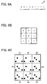
- FIG. 9A is an illustration of third embedded data to be embedded into an embedded area of the original image of FIG. 4 according to an example embodiment of the present invention.
- FIG. 9B is an illustration of an example arrangement determined by the embedding apparatus of FIG. 1 ;
- FIG. 9C is an illustration of a plurality of patterns embedded into the embedded area of the original image of FIG. 4 , based on the third embedded data of FIG. 9A ;
- FIG. 10 is an illustration of an example processed image generated from the example original image of FIG. 4 ;
- FIG. 11A is an illustration of an example first type dot contained in the processed document image of FIG. 10 ;
- FIG. 11B is an illustration of an example second type dot contained in the processed document image of FIG. 10 ;
- FIG. 12 is an illustration of a processed document obtained by outputting the example processed image shown in FIG. 10 according to an example embodiment of the present invention
- FIG. 13 is an illustration of a processed document obtained by outputting the example processed image shown in FIG. 10 according to an example embodiment of the present invention
- FIG. 14 is a schematic block diagram illustrating the functional structure of a pattern embedder shown in FIG. 1 according to an example embodiment of the present invention
- FIG. 15 is a flowchart illustrating operation of generating a processed image, performed by the image processing apparatus of FIG. 1 , according to an example embodiment of the present invention
- FIG. 16 is an illustration of a plurality of first patterns each having a different absolute angle according to an example embodiment of the present invention.
- FIG. 17 is an illustration of a plurality of second patterns each having a different absolute angle according to an example embodiment of the present invention.
- FIG. 18A is an illustration of the first embedded data to be embedded into an embedded area of the original image of FIG. 4 according to an example embodiment of the present invention
- FIG. 18B is an illustration of an example arrangement determined by the embedding apparatus of FIG. 1 ;
- FIG. 18C is an illustration of a plurality of patterns embedded into the embedded area of the original image of FIG. 4 , based on the first embedded data of FIG. 18A ;
- FIG. 19A is an illustration of fourth embedded data to be embedded into an embedded area of the original image of FIG. 4 according to an example embodiment of the present invention.
- FIG. 19B is an illustration of an example arrangement determined by the embedding apparatus of FIG. 1 ;
- FIG. 19C is an illustration of a plurality of patterns embedded into the embedded area of the original image of FIG. 4 , based on the fourth embedded data of FIG. 19A ;
- FIG. 20A is an illustration of fifth embedded data to be embedded into an embedded area of the original image of FIG. 4 according to an example embodiment of the present invention
- FIG. 20B is an illustration of an example arrangement determined by the embedding apparatus of FIG. 1 ;
- FIG. 20C is an illustration of a plurality of patterns embedded into the embedded area of the original image of FIG. 4 , based on the fifth embedded data of FIG. 20A ;
- FIG. 21 is a schematic block diagram illustrating the functional structure of an extracting apparatus according to an example embodiment of the present invention.
- FIG. 22 is a schematic block diagram illustrating the functional structure of a pattern detector shown in FIG. 21 according to an example embodiment of the present invention.
- FIGS. 23A and 23B are flowcharts illustrating operation of obtaining embedded data from an original image, preformed by the extracting apparatus of FIG. 21 , according to an example embodiment of the present invention
- FIG. 24 is a schematic block diagram illustrating the functional structure of a pattern detector shown in FIG. 21 according to an example embodiment of the present invention.
- FIGS. 25A and 25B are flowcharts illustrating operation of obtaining embedded data from an original image, performed by the extracting apparatus of FIG. 21 , according to an example embodiment of the present invention
- FIG. 26 is an illustration for explaining operation of obtaining an angle of a plurality of patterns according to an example embodiment of the present invention.
- FIG. 27 is an illustration for explaining operation of obtaining an angle of a plurality of patterns according to an example embodiment of the present invention.
- FIG. 28 is an illustration for explaining operation of obtaining an angle of a plurality of patterns according to an example embodiment of the present invention.
- FIG. 29 is an illustration of a plurality of third patterns each having a different absolute angle according to an example embodiment of the present invention.
- FIG. 30 is an illustration of a plurality of fourth patterns each having a different absolute angle according to an example embodiment of the present invention.
- FIG. 31 is an illustration of a plurality of third patterns each having a different absolute angle according to an example embodiment of the present invention.
- FIG. 32 is an illustration of a plurality of fourth patterns each having a different absolute angle according to an example embodiment of the present invention.
- FIG. 33 is an illustration for explaining operation of obtaining an angle of a plurality of patterns according to an example embodiment of the present invention.
- FIG. 34 is an illustration for explaining operation of obtaining an angle of a plurality of patterns according to an example embodiment of the present invention.
- FIG. 35 is an illustration for explaining operation of obtaining an angle of a plurality of patterns according to an example embodiment of the present invention.
- FIGS. 36A and 36B are flowcharts illustrating operation of obtaining embedded data from an original image, preformed by the extracting apparatus of FIG. 21 , according to an example embodiment of the present invention
- FIG. 37 is a schematic block diagram illustrating the structure of an image forming apparatus according to an example embodiment of the present invention.
- FIG. 38 is a schematic block diagram illustrating the structure of an image processor shown in FIG. 37 according to an example embodiment of the present invention.
- FIG. 39 is a schematic block diagram illustrating the structure of an image forming system according to an example embodiment of the present invention.
- FIG. 40 is a schematic block diagram illustrating the structure of an image processing apparatus according to an example embodiment of the present invention.
- FIG. 1 illustrates an embedding apparatus 10 according to an example embodiment of the present invention.
- the embedding apparatus 10 is capable of embedding data into an original image.
- the embedding apparatus 10 includes an original image input 11 , an embedded data obtainer 12 , a pattern determinator 13 , a pattern embedder 14 , and a processed image output 15 .
- the original image input 11 inputs an original image to be processed.
- the original image input 11 may obtain the original image from the outside, such as a storage device or medium connected to the embedding apparatus 10 .
- the original image input 11 may receive an original document, and convert it into the original image using a scanner.
- the original image input 11 may read out the original image from a memory of the embedding apparatus 10 .
- the embedded data obtainer 12 obtains embedded data, which is to be embedded into an embedded area of the original image.
- the embedded data may be previously determined by default. Alternatively, the embedded data may be determined according to the user's preference.
- the embedded data contains information, which can be expressed by a predetermined number of digits, for example, as described below referring to any one of FIGS. 7A , 8 A, 9 A, 18 A, 19 A, and 20 A. Further, in this example, the embedded data is to be embedded in the form of a plurality of patterns.
- the pattern determinator 13 determines one or more types to be used for the plurality of patterns, based on the information contained in the embedded data. For example, if the embedded data contains information that can be expressed by either one of the binary characters 0 and 1, the pattern determinator 13 may select a first pattern type corresponding to the binary character 0, and a second pattern type corresponding to the binary character 1, from a plurality of pattern types available for use. In another example, if the embedded data contains information that can be expressed by at least one of the decimal characters 0 to 7, the pattern determinator 13 may select first to eighth pattern types respectively corresponding to the decimal characters 0 to 7, from the plurality of pattern types available for use.
- the pattern determinator 13 may further determine one or more colors to be used for the plurality of patterns based on the information contained in the embedded data. For example, a specific color may be assigned to each one of the pattern types of the plurality of patterns. Alternatively, the black color may be assigned to each one of the pattern types by default.
- the pattern determinator 13 may further determine a relative relationship to be used for the plurality of patterns based on the information contained in the embedded data.
- the pattern determinator 13 may determine an arrangement to be used for the plurality of patterns based on the information contained in the embedded data. For example, if the information contained in the embedded data can be expressed by eight digits, the pattern determinator 13 may determine an arrangement of the 8-digit information, which specifies the order or the position of each digit of the 8-digit information.
- the pattern determinator 13 may determine one or more angles to be used for the plurality of patterns based on the information contained in the embedded data.
- the angles of the plurality of patterns can be classified into two types: one type referred to as an absolute angle; and the other type referred to as a relative angle.
- the pattern determinator 13 may determine a first absolute angle of the pattern corresponding to the binary character 0, and a second absolute angle of the pattern corresponding to the binary character 1.
- the information contained in the embedded data may be expressed by a relative angle of at least two patterns, which indicates the relationship of the absolute angles of the at least two patterns.
- the pattern embedder 14 embeds the plurality of patterns into the embedded area of the original image to generate an embedded image.
- the pattern embedder 14 may generate the plurality of patterns using the pattern type, color, and relative relationship that are determined by the pattern determinator 13 . Accordingly, the plurality of patterns of the embedded image has the pattern type, color, and relative relationship, which are determined based on the embedded data.
- the processed image output 15 combines the embedded image and the original image into a processed image.
- the processed image may be further output as a printed document. Alternatively, the processed image may be sent as electronic data.
- the pattern embedder 14 of FIG. 1 has the functional structure shown in FIG. 2 .
- the pattern embedder 14 includes a color converter 141 , an arrangement converter 142 , and a pattern combiner 145 .
- Step S 11 inputs an original image to be processed, such as an original image D 0 shown in FIG. 4 , for example.
- the original image D 0 is a multivalue image containing confidential information.
- the original image D 0 may be classified into a foreground section 101 having a plurality of characters, and a background section 102 .
- Step S 12 obtains embedded data to be embedded into the original image D 0 .
- the embedded data is embedded into the background section 102 of the original image D 0 .
- the embedded data contains binary information, which can be expressed by either one of the binary characters 0 and 1, as illustrated in any one of FIGS. 7A , 8 A, and 9 A. Further, the embedded data is embedded in the form of a plurality of patterns.
- Step S 13 selects one or more pattern types of the plurality of patterns based on the information contained in the embedded data.
- the information contained in the embedded data can be expressed by either one of the binary characters 0 and 1, two pattern types are selected including a first pattern P 1 of FIG. 5 corresponding to the binary character 0, and a second pattern P 2 of FIG. 6 corresponding to the binary character 1.
- the first and second patterns P 1 and P 2 provide different characteristic information, such as the number of dots, density of dots, arrangement of dots, distance between dots, etc. Further, the characteristic information of the first pattern P 1 and the characteristic information of the second pattern P 2 are partially identical from each other. More specifically, referring to FIG.
- the first pattern P 1 contains a first dot PD 1 , a second dot PD 2 , and a third dot PD 3 .
- the second pattern P 2 contains a fourth dot PD 4 in addition to the first, second, and third dots PD 1 , PD 2 , and PD 3 that are identical to the dots of the first pattern P 1 .
- the first pattern P 1 and the second patter P 2 may be stored for further processing.
- Step S 14 of FIG. 3 determines one or more colors to be used for the plurality of patterns based on the information contained in the embedded data.
- the color of the first pattern P 1 and the color of the first pattern P 2 are determined to be partially different from each other. More specifically, the black color is assigned to each one of the first dot PD 1 , second dot PD 2 , and third dot PD 3 .
- the gray color is assigned to the fourth dot PD 4 .
- the colors of the first pattern P 1 and the second pattern P 2 may be stored for further processing.
- Step 815 determines an arrangement to be used for the plurality of patterns based on the information contained in the embedded data.
- the arrangement of the plurality of patterns is determined in a corresponding manner with the size of the information contained in the embedded data.
- the arrangement that can form a 4 ⁇ 2 block may be selected as illustrated in FIG. 7B .
- the arrangement that can form a 3 ⁇ 3 block may be selected as illustrated in FIG. 8B .
- the arrangement that can form a 3 ⁇ 3 block may be selected as illustrated in FIG. 9B .
- the arrangement determined by the pattern determinator 13 may be stored for further processing.
- Step S 17 embeds the plurality of patterns into the background section 102 of the original image D 0 to generate an embedded image.
- Step S 17 may be performed by the pattern embedder 14 of FIG. 1 having the functional structure of FIG. 2 .
- the color converter 141 converts the embedded data into color information of the plurality of patterns, using the colors determined by the pattern determinator 13 .
- the pattern determinator 13 determines the color of the first pattern P 1 to be black, and the color of the second pattern P 2 to be partially black and partially gray. If the digit of the information corresponds to the binary character 0, the color information representing black is obtained. If the digit of the information corresponds to the binary character 1, the color information representing the combination of black and gray is obtained.
- the arrangement converter 142 converts the embedded data into arrangement information of the plurality of patterns, using the arrangement determined by the pattern determinator 13 .
- the pattern determinator 13 determines that the arrangement forming the 4 ⁇ 2 block is used.
- the pattern determinator 13 determines that the arrangement forming the 3 ⁇ 3 block is used.
- the arrangement information of the plurality of patterns is obtained, which specifies the position of each digit of the information or the order of each digit relative to other digits in the information.
- the pattern combiner 145 of FIG. 2 generates the plurality of patterns using the pattern types that are determined by the pattern determinator 13 . Further, the pattern combiner 145 causes the plurality of patterns to have the determined colors and the determined arrangement, using the color information and the arrangement information. The plurality of patterns is then embedded into the background section 102 of the original image D 0 of FIG. 4 .
- the pattern embedder 14 generates eight unit areas A 1 to AB according to the arrangement shown in FIG. 7B .
- the binary character 0 of the first embedded data I 1 is embedded using the first pattern P 1 having the black color dots.
- the binary character 1 of the first embedded data I 1 is embedded using the second pattern P 2 having the black color dots and the gray color dot.
- the first patterns P 1 are respectively embedded into the unit areas A 1 , A 4 , and A 7 .
- the second patterns P 2 are respectively embedded into the unit areas A 2 , A 3 , A 5 , A 6 , and AB.
- the pattern embedder 14 generates nine unit areas A 1 to A 9 according to the arrangement shown in FIG. 8B .
- the binary character 0 of the second embedded data I 2 is embedded using the first pattern P 1 having the black color dots.
- the binary character 1 of the second embedded data I 2 is embedded using the second pattern P 2 having the black color dots and the gray color dot.
- the first patterns P 1 are respectively embedded into the unit areas A 1 , A 6 , A 7 , and AB.
- the second patterns P 2 are respectively embedded into the unit areas A 2 , A 3 , A 4 , A 5 , and A 9 .
- the pattern embedder 14 generates nine unit areas A 1 to A 9 according to the arrangement shown in FIG. 9B .
- the binary character 0 of the third embedded data I 3 is embedded using the first pattern P 1 having the black color dots.
- the binary character 1 of the third embedded data I 3 is embedded using the second pattern P 2 having the black color dots and the gray color dot.
- the first patterns P 1 are respectively embedded into the unit areas A 1 , A 2 , and A 5 .
- the second patterns P 2 are respectively embedded into the unit areas A 3 , A 4 , A 6 , A 7 , A 8 , and A 9 .
- the plurality of patterns representing the embedded data is embedded into the entire portion of the background section 102 of the original image D 0 .
- the plurality of patterns is repeatedly embedded.
- a selected portion of the background section 102 may be embedded with one or more sets of the plurality of patterns.
- Step S 18 combines the embedded image and the original image into a processed image.
- the plurality of patterns is embedded into the entire portion of the background section 102 as illustrated in FIG. 10 .
- the background section 102 is shown in the dark color to indicate the presence of the plurality of patterns.
- the processed image D 1 of FIG. 10 may look substantially similar to the original image D 0 of FIG. 4 , at least to the human eye.
- the size of each dot in the plurality of patterns may affect the appearance of the processed image when the processed image is output. For example, if a dot 103 a , shown in FIG. 11A , having the relatively large size is used for the plurality of patterns, the plurality of patterns may be perceptible to the human eye when it is output. In another example, if a dot 103 b , shown in FIG. 11B , having the relatively small size is used for the plurality of patterns, the plurality of patterns may not be perceptible to the human eye when it is output.
- Step S 19 outputs the processed image, and the operation ends.
- the processed image may be output as a printed document.
- the processed image may be displayed using a display device.
- the processed image may be output via a network.
- FIG. 3 may be performed in various other ways.
- Step S 12 may select embedded data according to the user's preference.
- the user's preference may include any kind of information regarding the characteristic information of the pattern including the color of the pattern, the size of information contained in the embedded data, the processing time, the easy of detection, etc.
- Step S 13 may select any pattern type other than the dot pattern type described above referring to FIG. 5 or 6 .
- a line pattern type or a design pattern type may be used. Further, Step S 13 may not be performed when the pattern type is previously determined.
- Step S 14 may not be performed when the pattern is previously set to be monochrome or any other color by default. Further, Steps S 13 and S 14 may be performed at the same time as the color is a part of the characteristic information of the plurality of patterns.
- the characteristic information or the relative relationship of the plurality of patterns which may be determined by the pattern determinator 13 in any one of Steps S 13 , S 14 , and S 15 , may be stored in the form of conversion table. Using the conversion table, Step S 17 can easily convert embedded data into the plurality of patterns.
- Step S 17 may obtain the color information or the arrangement information without performing any conversion on the embedded data. Accordingly, the pattern embedder 14 may not require any information from the embedded data obtainer 12 .
- Step S 18 or S 19 may not be performed.
- the embedded image may be stored in a corresponding manner with the original image for later use.
- the embedded data may be embedded into any area other than the background section 102 of the original image D 0 .
- the embedded data may be embedded into a selected portion of the original image D 0 in the form of mark.
- the background section 102 may be further segmented into a message area 102 a and a base area 102 b.
- the embedded data is embedded into the base area 102 b in the form of a plurality of patterns with each pattern having at least one dot 103 b shown in FIG. 11B .
- the message area 102 a of the background section 102 is embedded with a plurality of patterns with each pattern having at least one dot 103 a shown in FIG. 11A .
- the dot 103 a of the message area 102 a becomes visible to the user, while the dot 103 b of the base area 102 b remains invisible.
- the embedded data is embedded into the base area 102 b in the form of a plurality of patterns with each pattern having at least one dot 103 a shown in FIG. 11A .
- the message area 102 a of the background section 102 is embedded with a plurality of patterns with each pattern having at least one dot 103 b shown in FIG. 11 .
- the dot 103 a of the base area 102 b becomes visible to the user, while the dot 103 b of the message area 102 a remains invisible.
- the amount of the embedded data contained in the plurality of patterns can be easily adjusted. Further, the amount of the embedded data can be adjusted by determining a number of pattern types of the plurality of patterns. More specifically, the amount of embedded data I is expressed by the following equation if the binary system is used:
- n corresponds to the number of unit areas that is specified by the arrangement of the plurality of patterns, and N corresponds to the number of pattern types of the plurality of patterns.
- FIG. 15 operation of generating a processed image, performed by the embedding apparatus 10 of FIG. 1 , is explained according to an example embodiment of the present invention.
- the operation of FIG. 15 is substantially similar to the operation of FIG. 3 .
- the differences include the addition of Step S 16 , and the functional structure of the pattern embedder 14 of FIG. 1 .
- the pattern embedder 14 of FIG. 1 has the functional structure shown in FIG. 14 .
- the pattern embedder 14 includes the color converter 141 , the arrangement converter 142 , the pattern combiner 145 , an angle converter 143 , and a pattern rotator 144 .
- Step S 16 determines one or more angles to be used for the plurality of patterns based on the information contained in the embedded data.
- each one of the plurality of patterns has two types of angles: one referred to as an absolute angle and the other referred to as a relative angle.
- the absolute angle is an angle of the pattern relative to the upright position of the pattern, i.e., the upright position of the original image.
- the absolute angle can be any value between 0 and 360 degrees.
- a predetermined number of angles may be used, which may be obtained by quantizing the continuous range of angle based on a predetermined unit angle u 1 .
- the continuous range of angle i.e., 360 degrees is divided by the unit angle u 1 of 60 degrees to obtain six levels of the absolute angles.
- the number of levels of the absolute angles, or the number of absolute angles is referred to as a quantization number q.
- the absolute angle of the first pattern P 1 of FIG. 5 may be expressed by at least one of the six angles illustrated in FIG. 16 .
- the first pattern P 1 has the absolute angle R 10 when it is placed in the upright position.
- the first pattern P 1 has the absolute angle R 11 when it is placed in the position rotated by one unit angle, i.e., 60 degrees, from the upright position.
- the first pattern P 1 has the absolute angle R 12 when it is placed in the position rotated by two unit angles, i.e., 120 degrees, from the upright position.
- the first pattern P 1 has the absolute angle R 13 when it is placed in the position rotated by three unit angles, i.e., 180 degrees, from the upright position.
- the first pattern P 1 has the absolute angle R 14 when it is placed in the position rotated by four unit angles, i.e., 240 degrees, from the upright position.
- the first pattern P 1 has the absolute angle R 15 when it is placed in the position rotated by five unit angles, i.e., 300 degrees, from the upright position.
- the arrow shown in FIG. 16 is provided to indicate the orientation of each pattern. Further, in this example, the first pattern P 1 is rotated clockwise.
- the absolute angle of the second pattern P 2 of FIG. 6 may be expressed by at least one of the six angles illustrated in FIG. 17 .
- the second pattern P 2 has the absolute angle R 20 when it is placed in the upright position.
- the second pattern P 2 has the absolute angle R 21 when it is placed in the position rotated by one unit angle, i.e., 60 degrees, from the upright position.
- the second pattern P 2 has the absolute angle R 22 when it is placed in the position rotated by two unit angles, i.e., 120 degrees, from the upright position.
- the second pattern P 2 has the absolute angle R 23 when it is placed in the position rotated by three unit angles, i.e., 180 degrees from the upright position.
- the second pattern P 2 has the absolute angle R 24 when it is placed in the position rotated by four unit angles, i.e., 240 degrees from the upright position.
- the second pattern P 2 has the absolute angle R 25 when it is placed in the position rotated by five unit angles, i.e., 300 degrees from the upright position.
- the arrow shown in FIG. 17 is provided to indicate the orientation of each pattern. Further, in this example, the second pattern P 2 is rotated clockwise.
- the relative angle of the first pattern P 1 and the second pattern P 2 may be specified based on the unit angle u 1 .
- the relative angle R 0 may be specified by setting the difference in absolute angle between the first pattern P 1 and the second pattern P 2 to be 0 degree.
- the relative angle R 1 may be specified by setting the difference in absolute angle between the first pattern P 1 and the second pattern P 2 to be one unit angle, i.e., 60 degrees.
- the relative angle R 2 may be specified by setting the difference in absolute angle between the first pattern P 1 and the second pattern P 2 to be two unit angles, i.e., 120 degrees.
- the relative angle R 3 may be specified by making the difference in absolute angle between the first pattern P 1 and the second pattern P 2 to be three unit angles, i.e., 180 degrees.
- the relative angle R 4 may be specified by setting the difference in absolute angle between the first pattern P 1 and the second pattern P 2 to be four unit angles, i.e., 240 degrees.
- the relative angle R 5 may be specified by setting the difference in absolute angle between the first pattern P 1 and the second pattern P 2 to be five unit angles, i.e., 300 degrees.
- the absolute angle or the relative angle is determined based on the information contained in the embedded data.
- the first embedded data I 1 having 8-bit information “01101101” is obtained.
- the pattern determinator 13 assigns the absolute angle R 10 to the binary character 0, and the absolute angle R 21 to the binary character 1. Further, the relative angle R 1 is assigned to the plurality of patterns.
- the fourth embedded data I 4 having 9-digit information “022220002” is obtained.
- the pattern determinator 13 assigns the absolute angle R 10 to the decimal character 0, and the absolute angle R 22 to the decimal character 2. Further, the relative angle R 2 is assigned to the plurality of patterns.
- the fifth embedded data I 5 having 9-digit information “551151111” is obtained.
- the pattern determinator 13 assigns the absolute angle R 15 to the decimal character 5, and the absolute angle R 21 to the decimal character 1. Further, the relative angle R 4 is assigned to the plurality of patterns.
- Step S 17 embeds the plurality of patterns into the background section 102 of the original image D 0 to generate an embedded image.
- Step S 17 may be performed by the pattern embedder 14 having the functional structure of FIG. 14 .
- the color converter 141 converts the embedded data into color information of the plurality of patterns using the colors determined by the pattern determinator 13 , in a substantially similar manner as described referring to FIGS. 2 and 3 .
- the arrangement converter 142 converts the embedded data into arrangement information of the plurality of patterns, using the arrangement determined by the pattern determinator 13 .
- the pattern determinator 13 determines that the arrangement forming the 4 ⁇ 2 block is used.
- the pattern determinator 13 determines that the arrangement forming the 3 ⁇ 3 block is used.
- the arrangement information of the plurality of patterns is obtained, which specifies the position of each digit of the information or the order of each digit relative to the other digits in the information.
- the angle converter 143 converts the embedded data into angle information of the plurality of patterns, using the angles determined by the pattern determinator 13 .
- the pattern determinator 13 determines that the absolute angles of the first pattern P 1 and the second pattern P 2 to be R 10 and R 21 , respectively. Further, the pattern determinator 13 determines that the relative angle between the first pattern P 1 and the second pattern P 2 to be R 1 . Based on this angle information, the pattern rotator 144 obtains the first pattern P 1 having the absolute degree R 10 and the second pattern P 2 having the absolute degree R 21 .
- the pattern determinator 13 determines that the absolute angles of the first pattern P 1 and the second pattern P 2 to be R 10 and R 22 , respectively. Further, the pattern determinator 13 determines that the relative angle between the first pattern P 1 and the second pattern P 2 to be R 2 . Based on this angle information, the pattern rotator 144 obtains the first pattern P 1 having the absolute degree R 10 and the second pattern P 2 having the absolute degree R 22 .
- the pattern determinator 13 determines that the absolute angles of the first pattern P 1 and the second pattern P 2 to be R 15 and R 21 , respectively. Further, the pattern determinator 13 determines that the relative angle between the first pattern P 1 and the second pattern P 2 to be R 4 . Based on this angle information, the pattern rotator 144 obtains the first pattern P 1 having the absolute degree R 15 and the second pattern P 2 having the absolute degree R 21 .
- the pattern combiner 145 generates the plurality of patterns using the pattern types that are determined by the pattern determinator 13 . Further, the pattern combiner 145 causes the plurality of patterns to have the determined colors, the determined arrangement, and the determined angles, using the color information, arrangement information, and angle information. The plurality of patterns is then embedded into the background section 102 of the original image D 0 of FIG. 4 .
- the pattern embedder 14 generates eight unit areas A 1 to A 8 according to the arrangement shown in FIG. 18B . Further, in this example, the binary character 0 of the first embedded data I 1 is embedded using the first pattern P 1 having the absolute angle R 10 . The binary character 1 of the first embedded data I 1 is embedded using the second pattern P 2 having the absolute angle R 21 . Further, the first pattern P 1 and the second pattern P 2 are embedded so as to have the relative angle R 1 .
- the pattern embedder 14 generates nine unit areas A 1 to A 9 according to the arrangement shown in FIG. 19B . Further, in this example, the decimal character 0 of the fourth embedded data I 4 is embedded using the first pattern P 1 having the absolute degree R 10 . The decimal character 2 of the fourth embedded data I 4 is embedded using the second pattern P 2 having the absolute degree R 22 . Further, the first pattern P 1 and the second pattern P 2 are embedded so as to have the relative angle R 2 .
- the pattern embedder 14 generates nine unit areas A 1 to A 9 according to the arrangement shown in FIG. 20B . Further, in this example, the decimal character 5 of the fifth embedded data I 5 is embedded using the first pattern P 1 having the absolute degree R 15 . The decimal character 1 of the fifth embedded data I 5 is embedded using the second pattern P 2 having the absolute degree R 21 . Further, the first pattern P 1 and the second pattern P 2 are embedded so as to have the relative angle R 4 .
- Step S 15 may be performed in various other ways, for example, as described above referring to FIG. 3 . Further, Step S 15 may not be performed. In such case, the arrangement converter 142 of FIG. 14 may not be provided. Furthermore, in Step S 16 , at least one of the absolute angle and the relative angle may be determined to generate the angle information.
- the amount of the embedded data contained in the plurality of patterns can be easily adjusted. More specifically, the amount of embedded data I is expressed by the following equation if the binary system is used:
- the extracting apparatus 20 is capable of extracting embedded data from an original image, when the original image has been embedded with the embedded data.
- the extracting apparatus 20 includes an original image input 21 , a color detector 22 , a pattern detector 23 , and an embedded data obtainer 24 .
- the original image input 21 inputs an original image to be processed.
- the original image is presumed to include an embedded area that has been embedded with embedded data in the form of a plurality of patterns. Further, the original image may be input in various ways, for example, as described above referring to the original image input 11 of FIG. 1 .
- the color detector 22 extracts one or more color components from the original image, and converts the original image into a binary image having the extracted color components.
- the color detector 22 when the plurality of patterns is embedded with the green color component and the original image is input with the RGB (red, green, blue) format, the color detector 22 extracts the green color component from the original image, and generates a binary image having the green color component.
- the color detector 22 when the plurality of patterns is embedded with the cyan and magenta color components and the original image is input with the RGB format, the color detector 22 first converts the original image from the RGB format to the CMY (cyan, magenta, yellow) format. The color detector 22 then extracts the cyan and magenta color components from the original image to generate a binary image having the cyan and magenta color components.
- the pattern detector 23 detects the plurality of patterns from the embedded area of the original image. In this example, the pattern detector 23 detects the plurality of patterns from the binary image generated by the color detector 22 using information regarding the plurality of patterns. In one example, the pattern detector 23 detects the plurality of patterns using the pattern matching method. In another example, the pattern detector 23 detects the plurality of patterns using characteristic information of the plurality of patterns.
- the embedded data obtainer 24 analyzes the plurality of patterns to obtain the embedded data of the original image. In one example, the embedded data obtainer 24 analyzes the characteristic information of the plurality of patterns, such as the pattern types of the plurality of patterns. In another example, the embedded data obtainer 24 analyzes the relative relationship of the plurality of patterns, such as the arrangement or the angles of the plurality of patterns.
- the pattern detector 23 of FIG. 21 has the functional structure shown in FIG. 22 .
- the pattern detector 23 includes a pattern extractor 231 , a pattern counter 232 , a first pattern detector 233 , and a second pattern detector 234 .
- Step S 101 inputs an original image to be processed, such as the processed image D 1 of FIG. 10 , for example.
- the processed image D 1 has the background section 102 , to which embedded data is embedded in the form of a plurality of patterns. Further, in this example, the processed image D 1 is input with the RGB format.
- the original image input 21 may determine whether the processed image D 1 is in the upright position. If the processed image D 1 is not in the upright position, the processed image D 1 is rotated to be in the upright position.
- Step S 102 extracts one or more color components from the background section 102 of the processed image D 1 .
- color component information of the plurality of patterns which indicates the color components used for the plurality of patterns, is stored in a memory of the extracting apparatus 20 of FIG. 1 .
- the color component information may be provided from the user, if such information is known to the user.
- the color component information may be obtained from the processed image D 1 , if such information has been embedded in the processed image D 1 together with the plurality of patterns.
- the plurality of patterns is presumed to be embedded with the cyan and magenta color components.
- the color detector 22 converts the background section 102 of the processed image D 1 from the RGB format to the CMY format.
- the color detector 22 then extracts the cyan and magenta components from the background section 102 .
- the color detector 22 generates a binary image by assigning the value 1 to the cyan and magenta components and the value 0 to the yellow component of the background section 102 .
- the pattern detector 23 detects the plurality of patterns using characteristic information of the pluratliy of patterns, as described below referring to Steps S 103 to S 114 . More specifically, in this example, the pattern detector 23 having the functional structure shown in FIG. 22 detects the first pattern P 1 of FIG. 5 and the second pattern P 2 of FIG. 6 .
- the pattern extractor 231 divides the binary image into a plurality of unit areas, and selects one of the plurality of unit areas for further processing.
- each unit area is embedded with the corresponding one of the plurality of patterns.
- the characteristic information may include any kind of information obtainable from the pattern, such as the number of dots, density of dots, distance between dots, etc.
- Step S 104 the first pattern detector 233 determines whether the selected pattern matches the first pattern P 1 by comparing the characteristic information of the selected pattern with the characteristic information of the first pattern P 1 .
- the characteristic information of the first pattern P 1 may be stored in the first pattern detector 233 . If the characteristic information of the selected pattern is substantially similar to the characteristic information of the first pattern P 1 (“YES” in Step S 104 ), the operation proceeds to Step S 106 to increase a detected number of the first pattern P 1 by one. If the characteristic information of the selected pattern is different from the characteristic information of the first pattern P 1 (“NO” in Step S 104 ), the operation proceeds to Step S 107 .
- Step S 107 the second pattern detector 234 of FIG. 22 determines whether the selected pattern matches the second pattern P 2 by comparing the characteristic information of the selected pattern with the characteristic information of the second pattern P 2 .
- the characteristic information of the second pattern P 2 may be stored in the second pattern detector 234 . If the characteristic information of the selected pattern is substantially similar to the characteristic information of the second pattern P 2 (“YES” in Step S 107 ), the operation proceeds to Step S 109 to increase a detected number of the second pattern P 2 by one. If the characteristic information of the selected pattern is different from the characteristic information of the second pattern P 2 (“NO” in Step S 109 ), the operation proceeds to Step S 110 .
- Step S 110 the pattern extractor 231 determines whether all unit areas of the binary image are processed. If all unit areas have been processed (“YES” in Step S 110 ), the operation proceeds to Step S 111 of FIG. 23B . If all unit areas have not been processed (“NO” in Step S 110 ), the operation returns to Step S 103 to select another unit area to determine whether the selected pattern matches either one of the first pattern P 1 and the second pattern P 2 .
- Step S 111 the first pattern detector 233 of FIG. 23 determines whether the detected number of the first pattern P 1 is greater than a first reference value Ref 1 .
- the first reference value Ref 1 is previously stored in the first pattern detector 233 . If the detected number is greater than the first reference value Ref 1 (“YES” in Step S 111 ), the operation proceeds to step S 112 to determine that the first pattern P 1 is detected and output information regarding the detected first pattern P 1 to the embedded data obtainer 24 . If the detected number is equal to or less than the first reference value Ref 1 (“NO” in Step S 111 ), the operation ends to return an error message indicating that the first pattern P 1 is not detected.
- Step S 113 the second pattern detector 234 of FIG. 22 determines whether the detected number of the second pattern P 2 is greater than a second reference value Ref 2 .
- the second reference value Ref 2 is stored in the second pattern detector 234 . If the detected number is greater than the second reference value Ref 2 (“YES” in Step S 113 ), the operation proceeds to Step S 114 to determine that the second pattern P 2 is detected and output information regarding the detected second pattern P 2 to the embedded data obtainer 24 . If the detected number is equal to or less than the second reference value Ref 2 (“NO” in Step S 113 ), the operation ends to return an error message indicating the second pattern P 2 is not detected.
- the embedded data obtainer 24 of FIG. 22 analyzes the first pattern P 1 and the second pattern P 2 , which are detected by the pattern detector 23 .
- the first pattern P 1 and the second pattern P 2 are analyzed using the arrangement information of the plurality of patterns, which may be stored in a memory of the extracting apparatus 20 of FIG. 1 .
- the arrangement information may be provided from the user, if such information is known to the user.
- the arrangement information may be obtained from the processed image D 1 , if such information has been embedded in the processed image D 1 together with the plurality of patterns.
- the embedded data obtainer 24 extracts a set of the first pattern P 1 and the second pattern P 2 , which can form the 4 ⁇ 2 block, from the detected first pattern P 1 and the second pattern P 2 .
- the embedded data obtainer 24 extracts a set of the first pattern P 1 and the second pattern P 2 , which can form the 3 ⁇ 3 block, from the detected first pattern P 1 and the second pattern P 2 .
- the embedded data obtainer 24 obtains the embedded data of the processed image D 1 .
- the embedded data obtainer 24 converts the extracted set of the first pattern P 1 and the second pattern P 2 into a set of the binary character 0 and the binary character 1.
- FIGS. 23A and 23B may be performed in various other ways.
- Step S 102 of extracting one or more color components may not be performed, when the black color component is used for the plurality of patterns and the original image is input as a binary image.
- the binary image may be provided directly from the original image input 21 to the pattern detector 23 . Accordingly, the color detector 22 may not be provided.
- the pattern detector 23 of FIG. 21 may first determine whether the original image is embedded with embedded data. For example, one-bit information indicating whether the embedded data has been embedded may be previously embedded in the original image together with the plurality of patterns.
- the pattern counter 232 of FIG. 22 may count the number of a plurality of patterns that matches either one of the first pattern P 1 and the second pattern P 2 , which can be detected by the pattern extractor 231 . As shown in FIGS. 5 and 6 , any pattern that matches either one of the first pattern P 1 and the second pattern P 2 (“the detected pattern”) can be extracted using the characteristic information common to the first pattern P 1 and the second pattern P 2 , i.e., the characteristic information of the first, second, and third dots PD 1 , PD 2 , and PD 3 .
- the pattern counter 232 determines that at least one of the first pattern P 1 and the second pattern P 2 is detected, and provides information regarding the detected pattern to the first pattern detector 233 or the second pattern detector 234 . If the number of the detected patterns is equal to or less than the third reference value, the pattern counter 232 determines that none of the first pattern P 1 and the second pattern P 2 is detected, and sends an error message indicating that no pattern is detected.
- the third reference value may be stored in a memory of the extracting apparatus 20 .
- the plurality of patterns may be detected from a selected portion of the background section 102 . In such case, the number of unit areas to be processed may be reduced.
- Steps S 103 to S 114 of detecting the first pattern P 1 and the second pattern P 2 may be performed in various other ways.
- the first pattern P 1 or the second pattern P 2 may be detecting using the pattern matching method.
- the pattern detector 23 of FIG. 21 has the functional structure shown in FIG. 24 .
- the pattern detector 23 includes a first angle detector 235 , a second angle detector 236 , and a relative angle obtainer 237 , in addition to the pattern extractor 231 , the pattern counter 232 , the first pattern detector 233 , and the second pattern detector 234 of FIG. 22 .
- Step S 201 inputs an original image to be processed, such as the processed image D 1 of FIG. 10 , for example.
- the processed image D 1 has the background section 102 , to which embedded data is embedded in the form of a plurality of patterns. Further, in this example, the processed image D 1 is input with the RGB format.
- the original image input 21 may determine whether the processed image D 1 is in the upright position. If the processed image D 1 is not in the upright position, the processed image D 1 is rotated to be in the upright position.
- Step S 202 extracts one or more color components from the background section 102 of the processed image D 1 in a substantially similar manner as described referring to Step S 102 of FIG. 23A .
- the color detector 22 generates a binary image by assigning the value 1 to the cyan and magenta components and the value 0 to the yellow component of the background section 102 of the processed image D 1 .
- the pattern detector 23 detects the plurality of patterns using characteristic information and relative relationship of the plurality of patterns, as described below referring to Step S 203 to S 214 . More specifically, in this example, the pattern detector 23 having the functional structure shown in FIG. 24 detects a relative angle of the first pattern P 1 of FIG. 5 and the second pattern P 2 of FIG. 6 .
- Step S 203 the pattern extractor 231 divides the binary image into a plurality of unit areas, and obtains a selected pattern from one of the plurality of unit areas in a substantially similar manner as described referring to Step S 103 of FIG. 23A .
- the pattern extractor 231 further obtains characteristic information of the selected pattern.
- the first pattern detector 233 determines whether the selected pattern matches the first pattern P 1 by comparing the characteristic information of the selected pattern with the characteristic information of the first pattern P 1 .
- the characteristic information of the first pattern P 1 is stored for each one of the absolute angles obtainable from the first pattern P 1 .
- the number of absolute angles is determined based on the unit angle u 1 . If the unit angle u 1 is determined to be 60 degrees, the characteristic information of the first pattern P 1 is stored for each one of the six absolute angles R 10 , R 11 , R 12 , R 13 , R 14 , and R 15 as shown in FIG. 16 .
- Step S 204 If the characteristic information of the selected pattern is substantially similar to the characteristic information of the first pattern P 1 having at least one of the absolute angles R 10 to R 15 (“YES” in Step S 204 ), the operation proceeds to Step S 205 . If the characteristic information of the selected pattern is not similar to the characteristic information of the first pattern P 1 having at least one of the absolute angles R 10 to R 15 (“NO” in Step S 204 ), the operation proceeds to Step S 207 .
- the first angle detector 235 obtains the absolute angle of the selected pattern, i.e., the first pattern P 1 . Since the first pattern P 1 has six levels of absolute angles, the detected angle of the selected pattern is presumed to correspond to at least one of the six absolute angles R 10 to R 15 shown in FIG. 16 . More specifically, in this example, the first angle detector 235 determines whether the value of detected angle belongs to at least one of a plurality of ranges, with each range corresponding to each level of the absolute angles. For example, as illustrated in FIG.
- the first angle detector 235 determines that the selected pattern has the absolute angle R 10 . Similarly, if the selected pattern has the detected angle that falls in the range from 30 to 90 degrees, the first angle detector 235 determines that the selected pattern has the absolute angle R 11 .
- Step S 206 the first angle detector 235 increases, by one, a detected number of the first pattern P 1 for the absolute angle obtained in the previous step. For example, if the absolute angle R 10 is obtained in Step S 206 , the first angle detector 235 increases the detected number of the first pattern P 1 having the absolute angle R 10 . In this manner, the detected number of the first pattern P 1 is obtained for each one of the absolute angles R 10 to R 15 .
- the second pattern detector 234 determines whether the selected pattern matches the second pattern P 2 by comparing the characteristic information of the selected pattern with the characteristic information of the second pattern P 2 .
- the characteristic information of the second pattern P 2 is stored for each one of the absolute angles obtainable from the second pattern P 2 .
- the number of absolute angles is determined based on the unit angle u 1 . If the unit angle u 1 is determined to be 60 degrees, the characteristic information of the second pattern P 2 is stored for each one of the six absolute angles R 20 , R 21 , R 22 , R 23 , R 24 , and R 25 as shown in FIG. 17 .
- Step S 207 If the characteristic information of the selected pattern is substantially similar to the characteristic information of the second pattern P 2 having at least one of the absolute angles R 20 to R 25 (“YES” in Step S 207 ), the operation proceeds to Step S 208 . If the characteristic information of the selected pattern is not similar to the characteristic information of the second pattern P 2 having at least one of the absolute angles R 20 to R 25 (“NO” in Step S 207 ), the operation proceeds to Step S 210 .
- Step S 208 the second angle detector 236 obtains the absolute angle of the selected pattern, i.e., the second pattern P 2 , in a substantially similar manner as described above referring to Step S 205 .
- Step S 209 the second angle detector 236 increases, by one, a detected number of the second pattern P 2 for the absolute angle obtained in the previous step. In this manner, the detected number of the second pattern P 2 is obtained for each one of the absolute angles R 20 to R 25 .
- Step S 210 the pattern extractor 231 determines whether all unit areas of the binary image are processed. If all unit areas have been processed (“YES” in Step S 210 ), the operation proceeds to Step S 211 of FIG. 25B . If all unit areas have not been processed (“NO” in Step S 210 ), the operation returns to Step S 203 to select another unit area to determine whether the selected pattern matches either one of the first pattern P 1 and the pattern P 2 .
- Step S 211 the first angle detector 235 determines whether the peak is detected among the detected numbers that are obtained in Step S 206 for each one of the absolute angles of the first pattern P 1 .
- the peak refers to the highest detected number
- a peak angle refers to the absolute angle having the highest detected number. If the peak is detected (“YES” in Step S 211 ), the operation proceeds to Step S 212 to determine that the peak angle is detected for the first pattern P 1 , and output information regarding the peak angle to the relative angle obtainer 237 of FIG. 24 . If the peak is not detected (“NO” in Step S 211 ), the operation ends to send an error message indicating that the angle of the first pattern P 1 is undetectable.
- Step S 213 the second angle detector 236 determines whether the peak is detected among the detected numbers that are obtained in Step S 209 for each one of the absolute angles of the second pattern P 2 , in a substantially similar manner as described referring to Step S 211 . If the peak is detected (“YES” in Step S 213 ), the operation proceeds to Step S 214 to determine that the peak angle is detected for the second pattern P 2 , and output information regarding the peak angle to the relative angle obtainer 237 of FIG. 24 . If the peak is not detected (“NO” in Step S 213 ), the operation ends to send an error message indicating that the angle of the second pattern P 2 is undetectable.
- Step S 215 the relative angle obtainer 237 analyzes the peak angle (“the first peak angle”) of the first pattern P 1 and the peak angle (“the second peak angle”) of the second pattern P 2 to obtain a relative angle between the first pattern P 1 and the second pattern P 2 .
- the relative angle can be obtained by calculating the difference between the first peak angle and the second peak angle.
- Step S 216 the embedded data obtainer 24 of FIG. 24 obtains the embedded data of the processed image D 1 .
- the embedded data obtainer 24 converts the relative angle into the decimal character of the embedded data.
- the embedded data obtainer 24 converts any one of the first peak angle and the second peak angle into the decimal character of the embedded data.
- the relative angle Rr of the first pattern P 1 and the second pattern P 2 may be obtained using the following equation:
- Rr
- Mod360/u 2 wherein Ra 1 corresponds to the absolute angle of the first pattern obtainable from the first peak angle, Ra 2 corresponds to the absolute angle of the second pattern obtainable from the second peak angle, and u 2 corresponds to the unit angle used for extracting.
- the Mod360/u 2 corresponds to the remainder obtained by dividing 360 degrees by the unit angle u 2 degrees.
- the unit angle u 2 for extracting is set to be equal to the unit angle u 1 for embedding.
- FIGS. 25A and 25B may be performed in various other ways as described above referring to FIGS. 23A and 23B .
- the original image input 21 may not determine whether the processed image D 1 is in the upright position, if the embedded data can be obtained only from the relative angle of the plurality of patterns. In such case, the absolute angle of the first pattern P 1 or the second pattern P 2 may not be obtained.
- Steps S 203 to S 215 of detecting the relative angle of the first pattern P 1 and the second pattern P 2 may be performed in various other ways.
- the unit angle u 1 or the quantization number q, which may be used for detecting the relative angle may be previously determined based on various parameters.
- any one of the detected absolute angle or the detected relative angle of the plurality of patterns may be classified into one of the ranges determined by the unit angle u 1 , each range corresponding to each level of the absolute angles determined during the embedding process.
- the detected absolute angle or the detected relative angle (collectively, referred to as “the detected angle”) may not be extracted with high accuracy due to various factors.
- the original image may be distorted during scanning due to the scanner capacity.
- the original document may be distorted during printing due to the printer capacity. Accordingly, the absolute angle or the relative angle may not be obtained with high accuracy.
- the value of the detected angle can be used for further processing only when the value falls in the range indicated by the black color.
- the value of the detected angle may not be accurately extracted when the value falls in the range indicated by the white color.
- the black color range has the amount of degrees substantially equal to the amount of degrees of the white color range. This indicates that the probability of accurately extracting the detected angle is 50 percent. This probability may be further reduced when the fluctuation range of the detected angle increases.
- the relative angle of the first pattern P 1 and the second pattern P 2 is presumed to be equal to the relative angle R 2 as shown in FIG. 26 .
- the detected absolute angle of the first pattern P 1 fluctuates in the range of 30 degrees
- the detected absolute angle of the first pattern P 1 may be inaccurately determined to be the absolute angle R 11 when the detected absolute angle falls in the black color range.
- the detected absolute angle of the second pattern P 2 fluctuates in the range of 30 degrees
- the detected absolute angle of the second pattern P 2 may be inaccurately determined to be the absolute angle R 23 when the detected absolute angle falls in the black color range.
- the relative angle of the first pattern P 1 and the second pattern P 2 may vary from R 1 to R 3 .
- FIG. 28 illustrates another example case in which the unit angle is set to be 30 degrees. Accordingly, the continuous range of angle is divided into twelve levels of absolute angles. Further, in this example, the value of the detected angle fluctuates in the range of 15 degrees from ⁇ 7.5 degrees to +7.5 degrees. In such case, the value of the detected angle can be used for further processing only when the value falls in the range indicated by the black color. From the comparison between the black color range and the white color range, the probability of accurately extracting the detected angle is determined to be 50 percent.
- any one of the unit angle u 1 for embedding, the quantization number q, a unit angle u 2 for extracting, the range used for extracting may be specified.
- the value of unit angle u 2 for extracting is specified to be equal to or greater than twice the fluctuation range f of the detected angle (referred to as the “rule 1”), as indicated by the following equation: u 2 ⁇ 2 *f.
- the fluctuation range of detected angle can be obtained by the empirical rule using a scanner or a printer, for example.
- the rule 2 may be described as the situation in which the unit angle u 1 for embedding is specified to be equal to twice the value of unit angle u 2 for extracting.
- the detected angle is presumed to fluctuate in the range of 30 degrees from ⁇ 15 degrees to +15 degrees.
- the unit angle u 2 for extracting is determined to be 60 degrees. Further, the unit angle u 1 for embedding is determined to be 120 degrees according to the second rule. Since the quantization number q is three, a plurality of patterns each having three absolute angles may be obtained during the embedding process. Further, the number of relative angles is limited to three. In the examples described below, the plurality of patterns can be classified into a third pattern P 3 and a fourth pattern P 4 .
- the third pattern P 3 may have the absolute angle R 30 corresponding to the upright position of the third pattern P 3 ; the absolute angle R 32 corresponding to the orientation rotated by one unit angle, i.e., 120 degrees from the upright position; and the absolute angle R 34 corresponding to the orientation rotated by two unit angles, i.e., 240 degrees from the upright position. At least one of the absolute angles R 30 , R 32 and R 34 may be selected when embedding the third pattern P 3 , for example, depending on the information contained in the embedded data. Similarly, as illustrated in FIG.
- the fourth pattern P 4 may have the absolute angle R 40 corresponding to the upright position; the absolute angle R 42 corresponding to the orientation rotated by one unit angle, i.e., 120 degrees from the upright position; and the absolute angle R 44 corresponding to the orientation rotated by two unit angles, i.e., 240 degrees from the upright position. At least one of the absolute angles R 40 , R 42 and R 44 may be selected when embedding the fourth pattern P 4 , for example, depending on the information contained in the embedded data.
- the relative angle may be determined to be at least one of the relative angle R 1 corresponding to 0 degree, the relative angle R 2 corresponding to 120 degrees, and the relative angle R 3 corresponding to 240 degrees.
- the third pattern P 3 may have the absolute angle R 31 corresponding to the orientation rotated by 60 degrees from the upright position; the absolute angle R 33 corresponding to the orientation rotated by one unit angle, i.e., 120 degrees from the absolute angle R 31 ; and the absolute angle R 35 corresponding to the orientation rotated by two unit angles, i.e., 240 degrees from the absolute angle R 31 .
- At least one of the absolute angles R 31 , R 33 and R 35 may be selected when embedding the third pattern P 3 , for example, depending on the information contained in the embedded data.
- the fourth pattern P 4 may have the absolute angle R 41 corresponding to the orientation rotated by 60 degrees from the upright position; the absolute angle R 43 corresponding to the orientation rotated by one unit angle, i.e., 120 degrees from the absolute angle R 41 ; and the absolute angle R 45 corresponding to the orientation rotated by two unit angles, i.e., 240 degrees from the absolute angle R 41 . At least one of the absolute angles R 41 , R 43 and R 45 may be selected when embedding the fourth pattern P 4 , for example, depending on the information contained in the embedded data.
- the relative angle may be determined to be at least one of the relative angle R 1 corresponding to 0 degree, the relative angle R 2 corresponding to 120 degrees, and the relative angle R 3 corresponding to 240 degrees.
- FIGS. 33 to 35 operation of determining the unit angle u 2 for extracting is explained according to an example embodiment of the present invention.
- an original image is presumed to be embedded with the third pattern P 3 having the absolute angle R 30 and the fourth pattern P 4 having the absolute angle R 42 .
- the relative angle of the third pattern P 3 and the fourth pattern P 4 is presumed to be R 2 , i.e., 120 degrees.
- the fluctuation range of detected angle is set to be equal to 30 degrees.
- the unit angle u 2 for extracting is determined to be equal to or greater than 60 degrees.
- the continuous angle of degree is divided by 60 degrees to obtain six ranges as illustrated in FIG. 26 .
- the detected angle can be then classified into one of the six ranges in a substantially similar manner as described above referring to FIG. 26 .
- the absolute angle R 30 of 0 degree may be inaccurately detected as the detected absolute angle of 30 degrees (indicated by a 1 ), and the absolute angle R 42 of 120 degrees may be inaccurately detected as the detected absolute angle of 150 degrees (indicated by a 2 ). In such case, the absolute angle R 30 or the absolute angle R 42 may not be accurately detected. As a result, the relative angle of the third pattern P 3 and the fourth pattern P 4 may not be accurately detected.
- the number of ranges that has been generated based on the unit angle u 2 for extracting may be reduced by combining two ranges that ate adjacent from each other into one range.
- the combination of two ranges may be determined based on the detected angle. For example, as illustrated in any one of FIGS. 33 and 34 , a first range to which the detected angle belongs, and a second range adjacent to the first range, may be combined into one range.
- the combination of two ranges may be previously defined by default, for example, as illustrated in FIG. 35 .
- the combination of two ranges may be determined based on the angle information indicating the absolute or relative angles of the plurality of patterns.
- the range from ⁇ 30 degrees to 30 degrees and the range from 30 degrees to 90 degrees are combined into one range from ⁇ 30 degrees to 90 degrees.
- the range from 90 degrees to 150 degrees and the range from 150 degrees to 210 degrees are combined into one range from 90 degrees to 210 degrees.
- the range from 210 degrees to 270 degrees and the range from 270 degrees to 330 degrees are combined into one range from 210 degrees to 330 degrees.
- the range from 30 degrees to 90 degrees and the range from 90 degrees to 150 degrees are combined into the range from 30 degrees to 150 degrees.
- the range from 150 degrees to 210 degrees and the range from 210 degrees to 270 degrees are combined into the range from 150 degrees to 270 degrees.
- the range from 270 degrees to 330 degrees and the range from ⁇ 30 degrees to 30 degrees are combined into the range from 270 degrees to 30 degrees.
- the absolute angle or relative angle of the plurality of patterns can be obtained with high accuracy.
- the detected absolute angle of 30 degrees falls in the range from ⁇ 30 degrees to 90 degrees, the detected absolute angle is determined to be the absolute angle R 30 of 0 degree.
- the detected absolute angle of 150 degrees falls in the range from 90 degrees to 210 degrees, the detected absolute angle is determined to be the absolute angle R 42 of 120 degrees.
- the relative angle of the third pattern P 3 and the fourth pattern P 4 is determined to be R 1 .
- the absolute angle R 30 of 0 degree is accurately detected (indicated by a 1 ), and the absolute angle R 42 of 120 degrees is accurately detected.
- the absolute angles of the third pattern P 3 and the fourth pattern P 4 can be respectively extracted with high accuracy. Further, the relative angle of the third pattern P 3 and the fourth pattern P 4 can be accurately extracted.
- the value of unit angle u 2 for extracting may not be necessarily equal to or greater than twice the fluctuation range of the detected angle, as the rule 1 states. More specifically, the value of unit angle u 2 for extracting can be specified to be greater than the fluctuation range f of the detected angle (referred to as the “rule 3”), as expressed by the following equation: u2>f.
- the unit angle u 2 for extracting can be set to be substantially equal to 30 degrees, when the fluctuation range of the detected angle is 30 degrees. Further, the unit angle u 1 for embedding can be set to 60 degrees. If the rule 3 is applied instead of the rule 1, the amount of information that can be embedded as the embedded data may increase.
- the unit angle u 2 for extracting may be further broken down into one or more minimum unit angles s.
- the minimum unit angle s corresponds to the unit angle having the minimum value obtainable by quantizing the continuous range of angle. Since the range can be broken down into one or more unit angles u 2 and each one of the unit angles u 2 can be broken down into one or more minimum unit angles s, the range can be broken down into one or more minimum unit angles s.
- the rule 3 may be applied by obtaining the smallest value of the number x of minimum unit angles s that can satisfy the equation:
- f corresponds to the fluctuation range of the detected angle expressed in degree
- s corresponds to the value of minimum unit angle expressed in degree
- x corresponds to the number of minimum unit angles expressed in integer.
- the value of unit angle for extracting corresponds to the value s*x.
- the rule 2 may be applied by obtaining the largest value of the quantization number q that can satisfy the equation:
- the absolute angle or the relative angle can be expressed as a set of ⁇ s*x*2*0, s*x*2*1, . . . , s*x*2*(q ⁇ 1) ⁇ .
- FIGS. 36A and 36B operation of obtaining embedded data from an original image, performed by the extracting apparatus of FIG. 21 , is explained according to an example embodiment of the present invention.
- the operation of FIGS. 36A and 36B is substantially similar to the operation of FIGS. 25A and 25B .
- the differences include the addition of Step S 311 and Step S 313 shown in FIG. 36B .
- the first angle detector 235 determines the classification of the first peak angle, using any one of the above-described rules.
- the six ranges shown in FIG. 26 may be reclassified into three ranges as described above referring to any one of FIGS. 33 to 35 . According to these three ranges, the detected numbers obtained for the six angles are converted to the detected numbers for the three angles. From the converted detected numbers, the peak angle having the highest detected number is obtained for further processing.
- Step S 313 the second angle detector 236 determines the classification of the second peak angle, using any one of the above-described rules, in a substantially similar manner as described referring to Step S 311 .
- any one of the above-described embedding apparatus 10 of FIG. 1 , the extracting apparatus 20 of FIG. 21 , and other example embodiments of the present invention may be implemented in various ways, for example, as an image forming apparatus 300 shown in FIG. 37 , an image forming system 400 shown in FIG. 39 , or an image processing apparatus shown in FIG. 40 .
- the image forming apparatus 300 of FIG. 37 may be implemented by a multifunctional apparatus capable of performing a plurality of functions including the functions of scanning, printing, copying, etc.
- the image forming apparatus 300 includes a scanner 301 , image processor 302 , printer 303 , controller 304 , and operation panel 305 .
- the scanner 301 includes any kind of device capable of reading an original document into an original image to be processed.
- the image processor 302 includes any kind of device capable of applying various image processing to the original image.
- the printer 303 includes any kind of device capable of outputting the original image, such as a printer or a plotter.
- the operation panel 305 functions as a user interface. In this example, the operation panel 305 at least includes an input device allowing a user to input data such as a plurality of keys, and a display device displaying data to the user such as a liquid crystal display.
- the controller 304 controls at least one of the scanner 301 , image processor 302 , and printer 303 according to an instruction received from the operation panel 205 . As shown in FIG. 37 , the controller 304 includes a central processing unit (CPU) 3041 , read only memory (ROM) 3042 , and random access memory (RAM) 3043 .
- CPU central processing unit
- ROM read only memory
- RAM random access memory
- the image forming apparatus 300 may function as the extracting apparatus 20 of FIG. 21 .
- the image processor 302 may have the structure shown in FIG. 38 .
- the image processor 302 includes a filter 3021 , scaler 3022 , gamma processor 3033 , halftone processor 3034 , selector 3035 , color converter 3036 , pattern detector 3037 , and an embedded data obtainer 3038 .
- the controller 304 of FIG. 37 is incorporated into the image processor 302 .
- the scanner 301 may function as the original image input 21 of FIG. 21 .
- the scanner 301 reads an original document into an original image to be processed, according to an instruction received from the user via the operation panel 305 .
- the filter 3021 may apply preprocessing to the original image before providing the original image to the color converter 3036 .
- the color converter 3036 may function as the color detector 22 of FIG. 21 , which converts the original image into a binary image using one or more color components.
- the pattern detector 3037 may function as the pattern detector 23 of FIG. 21 , which detects a plurality of patterns from the original image or the binary image.
- the embedded data obtainer 3038 may function as the embedded data obtainer 24 of FIG. 21 , which converts the plurality of patterns into embedded data.
- the embedded data is output to the selector 3035 . Based on the embedded data, the selector 3035 controls operation of the printer 303 . Any one of the scaler 3022 , gamma processor 3033 , and halftone processor 3034 may apply to various image processing to the original image.
- the printer 303 operates according to an instruction received from the selector 3035 .
- the printer 303 when the embedded data is not obtained by the selector 3035 , the printer 303 is caused to print out the original image as the printed original document.
- the printer 303 when the embedded data is obtained by the selector 3035 , the printer 303 is caused to cancel printing of the original image.
- the printer 303 when the embedded data is obtained by the selector 3035 , the printer 303 is caused to conceal the information contained in the original image, for example, by making the plurality of patterns visible to the user.
- the printer 303 when the embedded data is obtained by the selector 3035 , the printer 303 is caused to notify the user that the original image is copy guarded, for example, by making a pattern or a mark visible to the user.
- the image forming apparatus 300 may function as the embedding apparatus 10 of FIG. 1 .
- the structure of the image processor 302 may differ from the structure shown in FIG. 38 .
- the pattern detector 3037 and the embedded data obtainer 3038 may not be provided.
- a pattern determinator functioning as the pattern determinator 13 of FIG. 1 and a pattern embedder functioning as the pattern embedder 14 of FIG. 1 may be additionally provided.
- the scanner 301 may function as the original image input 11 of FIG. 1 .
- the scanner 301 reads an original document into an original image to be processed, according to an instruction received from the user via the operation panel 305 .
- the operation panel 305 may function as the embedded data obtainer 12 by allowing the user to input embedded data or any parameters regarding the embedded data.
- the memory incorporated in the image processor 302 such as the ROM 3042 , may function as the embedded data obtainer 12 by storing information regarding the embedded data.
- a storage device such as a hard disk drive (HDD) may be provided.
- the printer 303 may function as the processed image output 15 , which outputs the processed image as a printed document.
- the operation panel 305 may function as the processed image by displaying the processed image using the display device.
- the image forming system 400 includes a scanner 401 , image processor 402 , printer 403 , controller 404 , operation panel 405 , and HDD 406 .
- the scanner 401 includes any kind of device capable of reading an original document into an original image to be processed.
- the image processor 402 includes any kind of device capable of applying various image processing to the original image.
- the printer 403 includes any kind of device capable of outputting the original image, such as a printer or a plotter.
- the controller 404 controls operation of the image forming system 400 ,
- the operation panel 305 functions as a user interface.
- the HDD 406 includes any kind of storage capable of storing a large amount of data.
- the HDD 406 may store an image processing program of the present invention.
- the CPU 4041 loads the image processing program onto a ROM 4042 , and causes the image forming system 400 to function as the embedding apparatus 10 of FIG. 1 or the extracting apparatus 20 of FIG. 21 .
- the image processing apparatus 500 includes a CPU 501 , ROM 502 , RAM 503 , hard disk drive (HDD) 504 , disc drive 505 , and an interface (I/F) 506 , which are connected via a bus 507 .
- the image processing apparatus 500 may be implemented by a personal computer, for example.
- the CPU 501 includes any kind of processor capable of controlling operation of the image processing apparatus 500
- the ROM 502 includes any kind of involatile memory, such as BIOS, for example.
- the RAM 503 functions as a work memory for the CPU 501 .
- the HDD 504 includes any kind of storage capable of storing a large amount of data.
- the disc drive 505 includes any kind of device capable of reading data from a removable disc 508 .
- the I/F 506 includes any kind of device capable of functioning as a user interface, such as an input device including a mouse or a keyboard, a display device, etc.
- the I/F 506 may further function as a network interface, which connects the image processing apparatus 500 to a network such as a local area network (LAN) or the Internet.
- LAN local area network
- the image processing program of the present invention may be installed on the HDD 204 from the removable disc 508 storing the image processing program.
- the image processing program may be further loaded onto the ROM 502 upon activation of the CPU 501 .
- the image processing program may be downloaded from any other device or apparatus via the network, through the interface 506 . Further, the image processing program may be uploaded from the image processing apparatus 500 to any other device or apparatus through the network.
- any one of the above-described and other methods of the example embodiments of the present invention may be embodied in the form of a computer program stored in any kind of storage medium.
- storage mediums include, but are not limited to, flexible disk, hard disk, optical discs, magneto-optical discs, magnetic tapes, involatile memory cards, ROM (read-only-memory), etc.
- any one of the above-described and other methods of the example embodiments of the present invention may be implemented by ASIC, prepared by interconnecting an appropriate network of conventional component circuits or by a combination thereof with one or more conventional general purpose microprocessors and/or signal processors programmed accordingly.
Landscapes
- Engineering & Computer Science (AREA)
- Multimedia (AREA)
- Signal Processing (AREA)
- Physics & Mathematics (AREA)
- General Physics & Mathematics (AREA)
- Theoretical Computer Science (AREA)
- Editing Of Facsimile Originals (AREA)
- Image Processing (AREA)
Applications Claiming Priority (4)
| Application Number | Priority Date | Filing Date | Title |
|---|---|---|---|
| JP2005067760 | 2005-03-10 | ||
| JP2005-067760 | 2005-03-10 | ||
| JP2005343852A JP2006287902A (ja) | 2005-03-10 | 2005-11-29 | 画像処理装置、画像処理方法、画像処理プログラム及び記録媒体 |
| JP2005-343852 | 2005-11-29 |
Publications (2)
| Publication Number | Publication Date |
|---|---|
| US20060256362A1 US20060256362A1 (en) | 2006-11-16 |
| US7609851B2 true US7609851B2 (en) | 2009-10-27 |
Family
ID=36480952
Family Applications (1)
| Application Number | Title | Priority Date | Filing Date |
|---|---|---|---|
| US11/369,964 Active 2028-08-27 US7609851B2 (en) | 2005-03-10 | 2006-03-08 | Embedding data into document and extracting embedded data from document |
Country Status (3)
| Country | Link |
|---|---|
| US (1) | US7609851B2 (enExample) |
| EP (1) | EP1701535A1 (enExample) |
| JP (1) | JP2006287902A (enExample) |
Cited By (4)
| Publication number | Priority date | Publication date | Assignee | Title |
|---|---|---|---|---|
| US20080166013A1 (en) * | 2006-12-15 | 2008-07-10 | Masaaki Ishikawa | Image processing device and image processing method |
| US20090161957A1 (en) * | 2007-12-20 | 2009-06-25 | Canon Kabushiki Kaisha | Constellation detection |
| US20090213397A1 (en) * | 2008-02-22 | 2009-08-27 | Ricoh Company, Ltd. | Apparatus, system, and method of process control |
| US10791239B2 (en) | 2018-03-20 | 2020-09-29 | Hewlett-Packard Development Company, L.P. | Encoding information in printed images by decreasing grayscale pixel values exceeding threshold |
Families Citing this family (16)
| Publication number | Priority date | Publication date | Assignee | Title |
|---|---|---|---|---|
| JP2004274092A (ja) * | 2002-07-23 | 2004-09-30 | Ricoh Co Ltd | 画像処理装置、画像処理方法、画像処理プログラム、及び画像処理プログラムを記憶する記憶媒体 |
| JP4719717B2 (ja) * | 2006-06-27 | 2011-07-06 | 株式会社リコー | 画像処理装置、画像処理方法及び画像処理プログラム |
| JP5005490B2 (ja) * | 2006-12-15 | 2012-08-22 | 株式会社リコー | 画像処理方法、画像処理装置及び画像処理プログラム |
| KR101203423B1 (ko) * | 2007-02-06 | 2012-11-21 | 삼성전자주식회사 | 화상처리장치 및 그 제어방법 |
| JP2008236127A (ja) * | 2007-03-19 | 2008-10-02 | Ricoh Co Ltd | 画像処理装置 |
| US8325970B2 (en) * | 2007-03-19 | 2012-12-04 | Ricoh Company, Limited | Apparatus, method, and computer product for image processing |
| US8180102B2 (en) * | 2007-03-19 | 2012-05-15 | Ricoh Company, Ltd. | Image processing device, image processing method, program, and recording medium |
| JP4929064B2 (ja) | 2007-05-15 | 2012-05-09 | 株式会社リコー | 秘匿処理装置および画像形成装置 |
| EP2001216A1 (en) * | 2007-06-08 | 2008-12-10 | Ricoh Company, Ltd. | Security encoding unit and image forming apparatus including same |
| JP5038235B2 (ja) * | 2008-06-06 | 2012-10-03 | 株式会社リコー | 情報処理装置、画像形成装置及びプログラム |
| JP2010087780A (ja) * | 2008-09-30 | 2010-04-15 | Fuji Xerox Co Ltd | 画像形成装置 |
| US8571298B2 (en) * | 2008-12-23 | 2013-10-29 | Datalogic ADC, Inc. | Method and apparatus for identifying and tallying objects |
| JP5039721B2 (ja) * | 2009-01-29 | 2012-10-03 | 京セラドキュメントソリューションズ株式会社 | 画像形成装置、画像読取装置 |
| JP6168084B2 (ja) * | 2015-03-16 | 2017-07-26 | コニカミノルタ株式会社 | 画像読取装置及びプログラム |
| JP6707947B2 (ja) * | 2016-03-29 | 2020-06-10 | 株式会社リコー | 画像処理装置、画像処理方法及びプログラム |
| CN114760392A (zh) * | 2022-06-15 | 2022-07-15 | 湖南工商大学 | 基于盲水印和非对称加密的文档篡改检测方法 |
Citations (10)
| Publication number | Priority date | Publication date | Assignee | Title |
|---|---|---|---|---|
| US5798844A (en) | 1993-07-23 | 1998-08-25 | Ricoh Company, Ltd. | Duplicator having function concerning specific mark put on recording sheet and image forming apparatus having function of processing confidential documents |
| US5946414A (en) | 1998-08-28 | 1999-08-31 | Xerox Corporation | Encoding data in color images using patterned color modulated image regions |
| JP2001086330A (ja) | 1999-09-16 | 2001-03-30 | Ricoh Co Ltd | 画像処理システム |
| JP2001197297A (ja) | 1999-11-02 | 2001-07-19 | Fuji Xerox Co Ltd | 画像処理装置及びコンピュータ読取可能な記憶媒体 |
| US20030021442A1 (en) | 2001-07-18 | 2003-01-30 | Masahiko Suzaki | Watermark Information embedment device and watermark information detection device |
| US20030133163A1 (en) | 2002-01-16 | 2003-07-17 | Wang Shen-Ge | Watermarked image generator and method of embedding watermarks into an input image |
| DE10217156A1 (de) | 2002-04-17 | 2003-11-13 | Andreas Brugger | Datenstreifen zur Codierung gedruckter Daten |
| EP1385327A2 (en) | 2002-07-23 | 2004-01-28 | Ricoh Company, Ltd. | Method, program, and apparatus for prohibiting a reproduction of an anti-copy document, and a medium storing the program |
| US6824240B2 (en) * | 2001-09-28 | 2004-11-30 | Canon Kabushiki Kaisha | Image processing apparatus and method and recording medium |
| JP2005102124A (ja) | 2003-08-27 | 2005-04-14 | Ricoh Co Ltd | 画像処理システム、画像処理方法、画像処理プログラム、及び画像処理プログラムを記憶する記憶媒体 |
Family Cites Families (4)
| Publication number | Priority date | Publication date | Assignee | Title |
|---|---|---|---|---|
| JPH0730743A (ja) * | 1993-07-06 | 1995-01-31 | Fuji Xerox Co Ltd | 画像処理装置 |
| JPH0730696A (ja) * | 1993-07-06 | 1995-01-31 | Fuji Xerox Co Ltd | 画像情報付加装置 |
| JP2005067760A (ja) | 2003-08-20 | 2005-03-17 | Hitachi Building Systems Co Ltd | 昇降機の故障状態表示装置 |
| JP4523339B2 (ja) | 2004-06-04 | 2010-08-11 | 新田ゼラチン株式会社 | 骨靭性向上用素材 |
-
2005
- 2005-11-29 JP JP2005343852A patent/JP2006287902A/ja active Pending
-
2006
- 2006-03-08 US US11/369,964 patent/US7609851B2/en active Active
- 2006-03-10 EP EP06251283A patent/EP1701535A1/en not_active Ceased
Patent Citations (10)
| Publication number | Priority date | Publication date | Assignee | Title |
|---|---|---|---|---|
| US5798844A (en) | 1993-07-23 | 1998-08-25 | Ricoh Company, Ltd. | Duplicator having function concerning specific mark put on recording sheet and image forming apparatus having function of processing confidential documents |
| US5946414A (en) | 1998-08-28 | 1999-08-31 | Xerox Corporation | Encoding data in color images using patterned color modulated image regions |
| JP2001086330A (ja) | 1999-09-16 | 2001-03-30 | Ricoh Co Ltd | 画像処理システム |
| JP2001197297A (ja) | 1999-11-02 | 2001-07-19 | Fuji Xerox Co Ltd | 画像処理装置及びコンピュータ読取可能な記憶媒体 |
| US20030021442A1 (en) | 2001-07-18 | 2003-01-30 | Masahiko Suzaki | Watermark Information embedment device and watermark information detection device |
| US6824240B2 (en) * | 2001-09-28 | 2004-11-30 | Canon Kabushiki Kaisha | Image processing apparatus and method and recording medium |
| US20030133163A1 (en) | 2002-01-16 | 2003-07-17 | Wang Shen-Ge | Watermarked image generator and method of embedding watermarks into an input image |
| DE10217156A1 (de) | 2002-04-17 | 2003-11-13 | Andreas Brugger | Datenstreifen zur Codierung gedruckter Daten |
| EP1385327A2 (en) | 2002-07-23 | 2004-01-28 | Ricoh Company, Ltd. | Method, program, and apparatus for prohibiting a reproduction of an anti-copy document, and a medium storing the program |
| JP2005102124A (ja) | 2003-08-27 | 2005-04-14 | Ricoh Co Ltd | 画像処理システム、画像処理方法、画像処理プログラム、及び画像処理プログラムを記憶する記憶媒体 |
Cited By (9)
| Publication number | Priority date | Publication date | Assignee | Title |
|---|---|---|---|---|
| US20080166013A1 (en) * | 2006-12-15 | 2008-07-10 | Masaaki Ishikawa | Image processing device and image processing method |
| US8238599B2 (en) * | 2006-12-15 | 2012-08-07 | Ricoh Company, Ltd. | Image processing device and image processing method for identifying a selected one or more embedding methods used for embedding target information |
| US20090161957A1 (en) * | 2007-12-20 | 2009-06-25 | Canon Kabushiki Kaisha | Constellation detection |
| US8244067B2 (en) * | 2007-12-20 | 2012-08-14 | Canon Kabushiki Kaisha | Constellation detection |
| US20090213397A1 (en) * | 2008-02-22 | 2009-08-27 | Ricoh Company, Ltd. | Apparatus, system, and method of process control |
| US8339678B2 (en) * | 2008-02-22 | 2012-12-25 | Ricoh Company, Ltd. | Apparatus, system, and method of process control based on the determination of embedded information |
| US10791239B2 (en) | 2018-03-20 | 2020-09-29 | Hewlett-Packard Development Company, L.P. | Encoding information in printed images by decreasing grayscale pixel values exceeding threshold |
| US11089180B2 (en) | 2018-03-20 | 2021-08-10 | Hewlett-Packard Development Company, L.P. | Encoding dot patterns into printed images based on source pixel color |
| US11277539B2 (en) | 2018-03-20 | 2022-03-15 | Hewlett-Packard Development Company, L.P. | Encoding information using disjoint highlight and shadow dot patterns |
Also Published As
| Publication number | Publication date |
|---|---|
| US20060256362A1 (en) | 2006-11-16 |
| EP1701535A1 (en) | 2006-09-13 |
| JP2006287902A (ja) | 2006-10-19 |
Similar Documents
| Publication | Publication Date | Title |
|---|---|---|
| US7609851B2 (en) | Embedding data into document and extracting embedded data from document | |
| US6526155B1 (en) | Systems and methods for producing visible watermarks by halftoning | |
| US5949903A (en) | Indentification of a particular color image using distribution, and circuitry for same | |
| JP3647405B2 (ja) | 画像処理装置及び画像処理方法 | |
| US20040051885A1 (en) | Image processing apparatus, image processing method, and image processing program product | |
| US6256110B1 (en) | Image processing apparatus and method and storage medium | |
| US7002709B1 (en) | Image processing system, image processing method, and image input system | |
| JPH10108022A (ja) | ハーフトーン・イメージ・データ獲得方法と装置およびハーフトーン印刷方法と装置 | |
| US8170275B2 (en) | Determining document authenticity in a closed-loop process | |
| JP2010045612A (ja) | 画像処理装置及びエッジ分類方法 | |
| US7372594B1 (en) | Image processing apparatus and method, and storage medium | |
| US20060268311A1 (en) | Image processing apparatus and image processing method | |
| US7058232B1 (en) | Image processing apparatus, method and memory medium therefor | |
| JP2006270972A (ja) | ハーフトーンウォーターマーキングおよび関連アプリケーション | |
| JPH11353436A (ja) | 表象コード及びそのコード化方法 | |
| US6853736B2 (en) | Image processing apparatus, image processing method and storage medium | |
| US6108098A (en) | Image processing apparatus and method | |
| US7630514B2 (en) | Embedding and extracting additional information in a document image | |
| Park et al. | Halftone blending between smooth and detail screens to improve print quality with electrophotographic printers | |
| JP2008154106A (ja) | 秘匿処理方法,画像処理装置および画像形成装置 | |
| US7253925B2 (en) | System and method for performing halftone processing of color and monochrome data | |
| JP3838981B2 (ja) | 画像処理装置、画像処理方法及び画像処理プログラム | |
| JP3684181B2 (ja) | 画像処理装置及び画像処理方法 | |
| US7616347B2 (en) | System and method for multi-bit halftoning | |
| JP3684178B2 (ja) | 画像処理装置及び画像処理方法 |
Legal Events
| Date | Code | Title | Description |
|---|---|---|---|
| AS | Assignment |
Owner name: RICOH COMPANY, LTD., JAPAN Free format text: ASSIGNMENT OF ASSIGNORS INTEREST;ASSIGNORS:GUAN, HAIKE;ISHIKAWA, MASAAKI;SHIMURA, HIROSHI;AND OTHERS;REEL/FRAME:017963/0365 Effective date: 20060526 |
|
| STCF | Information on status: patent grant |
Free format text: PATENTED CASE |
|
| FEPP | Fee payment procedure |
Free format text: PAYOR NUMBER ASSIGNED (ORIGINAL EVENT CODE: ASPN); ENTITY STATUS OF PATENT OWNER: LARGE ENTITY |
|
| CC | Certificate of correction | ||
| FPAY | Fee payment |
Year of fee payment: 4 |
|
| FPAY | Fee payment |
Year of fee payment: 8 |
|
| MAFP | Maintenance fee payment |
Free format text: PAYMENT OF MAINTENANCE FEE, 12TH YEAR, LARGE ENTITY (ORIGINAL EVENT CODE: M1553); ENTITY STATUS OF PATENT OWNER: LARGE ENTITY Year of fee payment: 12 |