US755865A - Oil-burning apparatus. - Google Patents
Oil-burning apparatus. Download PDFInfo
- Publication number
- US755865A US755865A US13810903A US1903138109A US755865A US 755865 A US755865 A US 755865A US 13810903 A US13810903 A US 13810903A US 1903138109 A US1903138109 A US 1903138109A US 755865 A US755865 A US 755865A
- Authority
- US
- United States
- Prior art keywords
- oil
- pipe
- tube
- burner
- coil
- Prior art date
- Legal status (The legal status is an assumption and is not a legal conclusion. Google has not performed a legal analysis and makes no representation as to the accuracy of the status listed.)
- Expired - Lifetime
Links
Images

Classifications
-
- F—MECHANICAL ENGINEERING; LIGHTING; HEATING; WEAPONS; BLASTING
- F23—COMBUSTION APPARATUS; COMBUSTION PROCESSES
- F23D—BURNERS
- F23D11/00—Burners using a direct spraying action of liquid droplets or vaporised liquid into the combustion space
- F23D11/36—Details, e.g. burner cooling means, noise reduction means
- F23D11/44—Preheating devices; Vaporising devices
Definitions
- the object of this invention is to provide an improved oil-burning apparatus designed for use in connection with heaters, ranges, or boilers and for other and similar purposes, a further object being to provide an oil-burner for this purpose which may be used in boilers, ranges, or other heaters as now constructed and provided with grates for burning coal or other material, the oil burner being adapted to be supported on the grate whenever desired or whenever necessary, inwhich event all that is necessary is to place the oil-burner in the boiler, range, or other heater, where it is supported by the ordinary grate therein; and with these and other objects in view the invention consists in an oil-burner and oilburning apparatus constructed as hereinafter described and claimed.
- supports d each of which is preferably composed of vertically-arranged members bolted together, as clearly shown in the drawings, and the supports 03 are provided at the top thereof withoutwardly and upwardly inclined baflie-plates d
- a tube 6 Secured in the top portions of the supports d is a tube 6, the ends of'which are closed, as shown at e and said tube 'is provided in the bottom thereof with a plurality of openings 6 which in the form of'construction shown are three in number.
- Another tube f, larger than the tube 6, is secured in the supports d below the tube 9, and the ends thereof are curved downwardly and open, as shown at and the top portion of this tube is provided with openings f which are arranged directly under the openings 6 in the tube 6 and are much larger than said openings 6 and the tube f is also provided centrally of the bottom thereof with a downwardly-directed tubular member f, which forms another opening similar to the end openings f
- a pipe-coil g is connected at one end with the tube 0, as shown at 9 and the coils of which extend downwardly and around the supports dand thetubes 6 and f, the bottom coil terminating at g
- An oil supply pipe h is connected with the bottom end of the coil 9 at 9 and this pipe isprovided with a valve 71,.
- a tank c' which may be located at any desired point and which is adapted to receive water under pressure, said water be" ing supplied thereto by means of a pipe 77, which communicates at the bottom thereof andwith which is connected a water-supply pipe 1: and a water-discharge pipe 6 and the pipe i may be connected with any suitable water-supply, such as a street-main, it being understood that the water supplied is always
- the tank 1' is also provided with an oil-supply pipe '5 which communicates with the top thereof and with a pressure-gage '5 and preferably with an oil and water gage i, and the pipes '6 41", and are each provided with a valve i
- a main oilfeed pipe 10 is also connected with the top portion of the tank 11, and this pipe is provided with a member 70 having a valve k and connected with a supplemental feed-pipe 70*, which in turn is connected with the pipe h, and said supplemental feed-pipe k is also provided with a similar drip-pipe it
- the oil as it passes through the coil g is converted into gas or vapor, and all this gas or vapor enters the tube 9 and is discharged through the openings in the bottom thereof into the tube f through the openings f in the top thereof, and said gas or vapor is highly heated and is discharged downwardly from the ends of the tube f and the central opening f in the bottom thereof and is ignited, and the flame thus produced rises and incloses the coil 9 and the tubes 6 and f, and said coiland tubes are maintained at a high degree of heat suitable to con- Vert the vapor from the oil into a fixed gas.
- bafl'le-plates d throw the flame and hot gases of combustion out against the inner walls of the boiler a and the same is thus highly heated, and by reason of the peculiar form of burner herein shown and described we are able to produce a very high degree of heat in a comparatively short time.
- the feed-pipe la is also provided with branch feed-pipes m, having valves m and these pipes may be employed for carrying oil to burners in a heating stove, range, or any other form of heater, and it will be understood that the burner herein shown and described may be employed in any kind or class of a heater, also in ranges of various forms,
- the grate a may be used whenever desired for burning coal or other material, and all that is necessary when it is desired to use my improved oil-burner is to simply place said burner in position, and for this purpose the door a of the boiler is made large enough to permit of the burner being inserted into the boiler therethrough or removed therefrom whenever necessary, and when it is desired to apply our improvement to ranges or other heaters the operation will be the same, the burner being inserted through the door of the range or other heater and being supported by the grate thereof.
- a burner comprising suitable supports, a tube secured in the top portion of said supports and provided with perforations or openings in the bottom thereof, another tube secured in said supports beneath the first-named tube and provided with perforations or openings in the top thereof which correspond with and are larger than those in the first-named tube, said last-named tube being also provided with downwardly directed openings, a pipe-coil inclosing said supports and said tubes and connected at its upper end with the firstnamed tube, and an oil-feed pipe connected with the lower end of said coil, said supports being also provided at their upper ends with baffle-plates, and said feed-pipe with a branch discharge-pipe adapted to discharge oil beneath said coil, substantially as shown and described.
Landscapes
- Engineering & Computer Science (AREA)
- Chemical & Material Sciences (AREA)
- Combustion & Propulsion (AREA)
- Mechanical Engineering (AREA)
- General Engineering & Computer Science (AREA)
- Feeding And Controlling Fuel (AREA)
Description
No. 755,865. PATENTED" MAR. '29, 1904. E. FRASER 6: E J. HOYT. OIL BURNING APPARATUS;
APPLICATION TILED JAN. 7, 1903.
N0 MODEL. 2 SHEETS-SHEBT l.
- THE NDRms arms cu. puurc-umou wnswmmou, D. c.
PATENTED MAR. 29, 1904. E. FRASER & E. J. HOYT. OIL BURNING APPARATUS.
APPLICATION FILED JAN. 7, 1903.
2 SHEETS-SEEM z N0 MODEL.
\lf kilv F I J II LL H I TH: NORRXS PETERS c0, moraumo WASNINGTON. u c
UNITED I STATES Patented March 29, 1904.
PATENT OFFICE.
EDWIN FRASER AND EDWARD J. HOYT, OF NEW YORK, N. Y.
OIL-BURNING APPARATUS.
SPECIFICATION forming part of Letters Patent No. 755,865, dated March 29, 1904.
' Application filed January 7, 1903.
To all whom it may concern:
Be it known that we, EDWIN FRASER and EDWARD J. HoY'r, citizens of the United States, residing at New York, in the county of New York and State of New York, have invented certain new and useful Improvements in Oil-Burning Apparatus, of which the following is a specification, such as will enable those skilled in the art to which it appertains to make and use the same.
The object of this invention is to provide an improved oil-burning apparatus designed for use in connection with heaters, ranges, or boilers and for other and similar purposes, a further object being to provide an oil-burner for this purpose which may be used in boilers, ranges, or other heaters as now constructed and provided with grates for burning coal or other material, the oil burner being adapted to be supported on the grate whenever desired or whenever necessary, inwhich event all that is necessary is to place the oil-burner in the boiler, range, or other heater, where it is supported by the ordinary grate therein; and with these and other objects in view the invention consists in an oil-burner and oilburning apparatus constructed as hereinafter described and claimed.
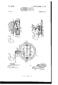
The invention is fully disclosed in the following specification, of which the accompanying drawings form a part, in which the separate parts of our improvement are designated by suitable reference characters in each of the views, and in which- Figure 1 is a side elevation of an apparatus involving our invention; Fig. 2, a section on the line 2 2 of Fig. 1; Fig. 3, a partial section on the line 3 3 of Fig. 2, and Fig. i a partial section on the line 4 i of Fig. 2.
In the drawings forming part of this specification we have indicated at a an ordinary vertical boiler; but in place of this we may use a heating stove, range, or similar article, and the boilera is provided with a fire-box (0 having a grate a below which is an ash-pit cf. Placed over the grate a is a perforated plate 6, and over this is preferably placed a sheet 0 of asbestos. We also employ an oil-burner proper which consists of vertically-arranged 'under pressure.
Serial No. 138,109. (No model.)
supports d, each of which is preferably composed of vertically-arranged members bolted together, as clearly shown in the drawings, and the supports 03 are provided at the top thereof withoutwardly and upwardly inclined baflie-plates d Secured in the top portions of the supports d is a tube 6, the ends of'which are closed, as shown at e and said tube 'is provided in the bottom thereof with a plurality of openings 6 which in the form of'construction shown are three in number. Another tube f, larger than the tube 6, is secured in the supports d below the tube 9, and the ends thereof are curved downwardly and open, as shown at and the top portion of this tube is provided with openings f which are arranged directly under the openings 6 in the tube 6 and are much larger than said openings 6 and the tube f is also provided centrally of the bottom thereof with a downwardly-directed tubular member f, which forms another opening similar to the end openings f A pipe-coil g is connected at one end with the tube 0, as shown at 9 and the coils of which extend downwardly and around the supports dand thetubes 6 and f, the bottom coil terminating at g An oil supply pipe h is connected with the bottom end of the coil 9 at 9 and this pipe isprovided with a valve 71,. We-
also provide a tank c', which may be located at any desired point and which is adapted to receive water under pressure, said water be" ing supplied thereto by means of a pipe 77, which communicates at the bottom thereof andwith which is connected a water-supply pipe 1: and a water-discharge pipe 6 and the pipe i may be connected with any suitable water-supply, such as a street-main, it being understood that the water supplied is always The tank 1' is also provided with an oil-supply pipe '5 which communicates with the top thereof and with a pressure-gage '5 and preferably with an oil and water gage i, and the pipes '6 41", and are each provided with a valve i A main oilfeed pipe 10 is also connected with the top portion of the tank 11, and this pipe is provided with a member 70 having a valve k and connected with a supplemental feed-pipe 70*, which in turn is connected with the pipe h, and said supplemental feed-pipe k is also provided with a similar drip-pipe it, having a valve in and adapted to discharge a small amount of oil onto the asbestos sheet 0 or on any other suitable support or in a receptacle placed under the coil g, and the supplemental feed-pipe 7c is also connected with the oil-supply pipe h.
The operation of this form of construction will be readily understood from the foregoing description when taken in connection with the accompanying drawings and the following statement thereof. It will be understood that the oil which is in the top portion of the tank 2' is always under pressure and is fed under pressure to the burner, and in practice we first discharge through the pipe a small amount of oil, which falls on the asbestos sheet 0, but may fall into any suitable receptacle provided therefor beneath the coil g. This oil is in practice ignited, and the flame therefrom heats the coil g, which is filled or partially filled with oil, it being understood that the flow of oil into the coil 9 is controlled by the valve I0 and the oil may be admitted into said coil after the latter has been heated, and this is the operation which is preferred. The oil as it passes through the coil g is converted into gas or vapor, and all this gas or vapor enters the tube 9 and is discharged through the openings in the bottom thereof into the tube f through the openings f in the top thereof, and said gas or vapor is highly heated and is discharged downwardly from the ends of the tube f and the central opening f in the bottom thereof and is ignited, and the flame thus produced rises and incloses the coil 9 and the tubes 6 and f, and said coiland tubes are maintained at a high degree of heat suitable to con- Vert the vapor from the oil into a fixed gas. The bafl'le-plates d throw the flame and hot gases of combustion out against the inner walls of the boiler a and the same is thus highly heated, and by reason of the peculiar form of burner herein shown and described we are able to produce a very high degree of heat in a comparatively short time.
The feed-pipe la is also provided with branch feed-pipes m, having valves m and these pipes may be employed for carrying oil to burners in a heating stove, range, or any other form of heater, and it will be understood that the burner herein shown and described may be employed in any kind or class of a heater, also in ranges of various forms,
without materially altering the construction thereof.
Our invention is not limited to the exact construction and arrangement and combination of parts herein shown and described, and many changes therein and modifications there of may be made Without departing from the spirit of our invention or sacrificing its advantages.
It will be understood that the grate a may be used whenever desired for burning coal or other material, and all that is necessary when it is desired to use my improved oil-burner is to simply place said burner in position, and for this purpose the door a of the boiler is made large enough to permit of the burner being inserted into the boiler therethrough or removed therefrom whenever necessary, and when it is desired to apply our improvement to ranges or other heaters the operation will be the same, the burner being inserted through the door of the range or other heater and being supported by the grate thereof.
Having fully described our invention, what we claim as new, and desire to secure by Letters Patent, is
In an apparatus of the class described, a burner comprising suitable supports, a tube secured in the top portion of said supports and provided with perforations or openings in the bottom thereof, another tube secured in said supports beneath the first-named tube and provided with perforations or openings in the top thereof which correspond with and are larger than those in the first-named tube, said last-named tube being also provided with downwardly directed openings, a pipe-coil inclosing said supports and said tubes and connected at its upper end with the firstnamed tube, and an oil-feed pipe connected with the lower end of said coil, said supports being also provided at their upper ends with baffle-plates, and said feed-pipe with a branch discharge-pipe adapted to discharge oil beneath said coil, substantially as shown and described.
In testimony that we claim the foregoing as our invention we have signed our names, in presence of the subscribing witnesses, this 30th day of December, 1902.
EDWIN FRASER. EDWARD J. HOYT. Witnesses:
J. C. LARSEN, F. A. STEWART.
Priority Applications (1)
| Application Number | Priority Date | Filing Date | Title |
|---|---|---|---|
| US13810903A US755865A (en) | 1903-01-07 | 1903-01-07 | Oil-burning apparatus. |
Applications Claiming Priority (1)
| Application Number | Priority Date | Filing Date | Title |
|---|---|---|---|
| US13810903A US755865A (en) | 1903-01-07 | 1903-01-07 | Oil-burning apparatus. |
Publications (1)
| Publication Number | Publication Date |
|---|---|
| US755865A true US755865A (en) | 1904-03-29 |
Family
ID=2824357
Family Applications (1)
| Application Number | Title | Priority Date | Filing Date |
|---|---|---|---|
| US13810903A Expired - Lifetime US755865A (en) | 1903-01-07 | 1903-01-07 | Oil-burning apparatus. |
Country Status (1)
| Country | Link |
|---|---|
| US (1) | US755865A (en) |
Cited By (1)
| Publication number | Priority date | Publication date | Assignee | Title |
|---|---|---|---|---|
| US10524427B2 (en) | 2004-02-13 | 2020-01-07 | Klondike Agricultural Products, LLC | Agricultural systems and methods |
-
1903
- 1903-01-07 US US13810903A patent/US755865A/en not_active Expired - Lifetime
Cited By (1)
| Publication number | Priority date | Publication date | Assignee | Title |
|---|---|---|---|---|
| US10524427B2 (en) | 2004-02-13 | 2020-01-07 | Klondike Agricultural Products, LLC | Agricultural systems and methods |
Similar Documents
| Publication | Publication Date | Title |
|---|---|---|
| US755865A (en) | Oil-burning apparatus. | |
| US401096A (en) | altice | |
| US40591A (en) | Improvement in gas-heating apparatus | |
| US833780A (en) | Steam-generator. | |
| US409360A (en) | Charles jones | |
| US270690A (en) | ostlund | |
| US52300A (en) | Improvement in gas-stoves | |
| US390757A (en) | Oil vaporizer and burner | |
| US568934A (en) | Automatic sight-feed crude-oil burner | |
| US880710A (en) | Furnace. | |
| US1084117A (en) | Liquid-fuel burner. | |
| US1005965A (en) | Vapor-burner. | |
| US649540A (en) | Heater for stoves. | |
| US626163A (en) | Steam-generator | |
| US418243A (en) | Petroleum-burner | |
| US1172269A (en) | Oil and gas burner. | |
| US353105A (en) | Lewis b | |
| US457414A (en) | Vapor or gas burner | |
| US380514A (en) | Generating retort and burner attached | |
| US320648A (en) | Chaeles d | |
| US1136185A (en) | Oil-burner. | |
| US1056504A (en) | Oil-burner. | |
| US1070587A (en) | Oil-burner attachment for stoves. | |
| US1021839A (en) | Oil-burner. | |
| US1167605A (en) | Oil-burner. |