US7463953B1 - Method for determining a tilt angle of a vehicle - Google Patents
Method for determining a tilt angle of a vehicle Download PDFInfo
- Publication number
- US7463953B1 US7463953B1 US11/821,318 US82131807A US7463953B1 US 7463953 B1 US7463953 B1 US 7463953B1 US 82131807 A US82131807 A US 82131807A US 7463953 B1 US7463953 B1 US 7463953B1
- Authority
- US
- United States
- Prior art keywords
- axis
- angle
- acceleration
- magnitude
- roll
- Prior art date
- Legal status (The legal status is an assumption and is not a legal conclusion. Google has not performed a legal analysis and makes no representation as to the accuracy of the status listed.)
- Active
Links
- 238000000034 method Methods 0.000 title claims abstract description 59
- 230000001133 acceleration Effects 0.000 claims abstract description 125
- 230000008859 change Effects 0.000 claims abstract description 34
- 238000005259 measurement Methods 0.000 claims description 19
- 230000006870 function Effects 0.000 description 22
- 230000005484 gravity Effects 0.000 description 10
- 230000008901 benefit Effects 0.000 description 8
- 238000004364 calculation method Methods 0.000 description 6
- 230000033001 locomotion Effects 0.000 description 6
- 230000000694 effects Effects 0.000 description 5
- 238000001514 detection method Methods 0.000 description 4
- 238000010586 diagram Methods 0.000 description 4
- 230000003068 static effect Effects 0.000 description 4
- XUIMIQQOPSSXEZ-UHFFFAOYSA-N Silicon Chemical compound [Si] XUIMIQQOPSSXEZ-UHFFFAOYSA-N 0.000 description 3
- 238000004519 manufacturing process Methods 0.000 description 3
- 230000008569 process Effects 0.000 description 3
- 229910052710 silicon Inorganic materials 0.000 description 3
- 239000010703 silicon Substances 0.000 description 3
- 238000004422 calculation algorithm Methods 0.000 description 2
- 230000006641 stabilisation Effects 0.000 description 2
- 238000011105 stabilization Methods 0.000 description 2
- 230000009466 transformation Effects 0.000 description 2
- 230000000996 additive effect Effects 0.000 description 1
- 238000004458 analytical method Methods 0.000 description 1
- 238000000594 atomic force spectroscopy Methods 0.000 description 1
- 230000003416 augmentation Effects 0.000 description 1
- 238000010276 construction Methods 0.000 description 1
- 230000008878 coupling Effects 0.000 description 1
- 238000010168 coupling process Methods 0.000 description 1
- 238000005859 coupling reaction Methods 0.000 description 1
- 230000007423 decrease Effects 0.000 description 1
- 238000005516 engineering process Methods 0.000 description 1
- 239000007788 liquid Substances 0.000 description 1
- 238000012986 modification Methods 0.000 description 1
- 230000004048 modification Effects 0.000 description 1
- 230000001902 propagating effect Effects 0.000 description 1
- 230000004044 response Effects 0.000 description 1
- 230000000717 retained effect Effects 0.000 description 1
- 230000035939 shock Effects 0.000 description 1
- 239000000758 substrate Substances 0.000 description 1
- 239000000725 suspension Substances 0.000 description 1
- XLYOFNOQVPJJNP-UHFFFAOYSA-N water Substances O XLYOFNOQVPJJNP-UHFFFAOYSA-N 0.000 description 1
Images


Classifications
-
- G—PHYSICS
- G01—MEASURING; TESTING
- G01C—MEASURING DISTANCES, LEVELS OR BEARINGS; SURVEYING; NAVIGATION; GYROSCOPIC INSTRUMENTS; PHOTOGRAMMETRY OR VIDEOGRAMMETRY
- G01C9/00—Measuring inclination, e.g. by clinometers, by levels
- G01C9/02—Details
- G01C9/08—Means for compensating acceleration forces due to movement of instrument
-
- B—PERFORMING OPERATIONS; TRANSPORTING
- B60—VEHICLES IN GENERAL
- B60K—ARRANGEMENT OR MOUNTING OF PROPULSION UNITS OR OF TRANSMISSIONS IN VEHICLES; ARRANGEMENT OR MOUNTING OF PLURAL DIVERSE PRIME-MOVERS IN VEHICLES; AUXILIARY DRIVES FOR VEHICLES; INSTRUMENTATION OR DASHBOARDS FOR VEHICLES; ARRANGEMENTS IN CONNECTION WITH COOLING, AIR INTAKE, GAS EXHAUST OR FUEL SUPPLY OF PROPULSION UNITS IN VEHICLES
- B60K35/00—Instruments specially adapted for vehicles; Arrangement of instruments in or on vehicles
- B60K35/10—Input arrangements, i.e. from user to vehicle, associated with vehicle functions or specially adapted therefor
-
- B—PERFORMING OPERATIONS; TRANSPORTING
- B60—VEHICLES IN GENERAL
- B60K—ARRANGEMENT OR MOUNTING OF PROPULSION UNITS OR OF TRANSMISSIONS IN VEHICLES; ARRANGEMENT OR MOUNTING OF PLURAL DIVERSE PRIME-MOVERS IN VEHICLES; AUXILIARY DRIVES FOR VEHICLES; INSTRUMENTATION OR DASHBOARDS FOR VEHICLES; ARRANGEMENTS IN CONNECTION WITH COOLING, AIR INTAKE, GAS EXHAUST OR FUEL SUPPLY OF PROPULSION UNITS IN VEHICLES
- B60K35/00—Instruments specially adapted for vehicles; Arrangement of instruments in or on vehicles
- B60K35/20—Output arrangements, i.e. from vehicle to user, associated with vehicle functions or specially adapted therefor
- B60K35/28—Output arrangements, i.e. from vehicle to user, associated with vehicle functions or specially adapted therefor characterised by the type of the output information, e.g. video entertainment or vehicle dynamics information; characterised by the purpose of the output information, e.g. for attracting the attention of the driver
-
- B—PERFORMING OPERATIONS; TRANSPORTING
- B60—VEHICLES IN GENERAL
- B60W—CONJOINT CONTROL OF VEHICLE SUB-UNITS OF DIFFERENT TYPE OR DIFFERENT FUNCTION; CONTROL SYSTEMS SPECIALLY ADAPTED FOR HYBRID VEHICLES; ROAD VEHICLE DRIVE CONTROL SYSTEMS FOR PURPOSES NOT RELATED TO THE CONTROL OF A PARTICULAR SUB-UNIT
- B60W40/00—Estimation or calculation of non-directly measurable driving parameters for road vehicle drive control systems not related to the control of a particular sub unit, e.g. by using mathematical models
- B60W40/12—Estimation or calculation of non-directly measurable driving parameters for road vehicle drive control systems not related to the control of a particular sub unit, e.g. by using mathematical models related to parameters of the vehicle itself, e.g. tyre models
-
- B—PERFORMING OPERATIONS; TRANSPORTING
- B60—VEHICLES IN GENERAL
- B60W—CONJOINT CONTROL OF VEHICLE SUB-UNITS OF DIFFERENT TYPE OR DIFFERENT FUNCTION; CONTROL SYSTEMS SPECIALLY ADAPTED FOR HYBRID VEHICLES; ROAD VEHICLE DRIVE CONTROL SYSTEMS FOR PURPOSES NOT RELATED TO THE CONTROL OF A PARTICULAR SUB-UNIT
- B60W50/00—Details of control systems for road vehicle drive control not related to the control of a particular sub-unit, e.g. process diagnostic or vehicle driver interfaces
- B60W50/08—Interaction between the driver and the control system
- B60W50/14—Means for informing the driver, warning the driver or prompting a driver intervention
-
- B—PERFORMING OPERATIONS; TRANSPORTING
- B60—VEHICLES IN GENERAL
- B60K—ARRANGEMENT OR MOUNTING OF PROPULSION UNITS OR OF TRANSMISSIONS IN VEHICLES; ARRANGEMENT OR MOUNTING OF PLURAL DIVERSE PRIME-MOVERS IN VEHICLES; AUXILIARY DRIVES FOR VEHICLES; INSTRUMENTATION OR DASHBOARDS FOR VEHICLES; ARRANGEMENTS IN CONNECTION WITH COOLING, AIR INTAKE, GAS EXHAUST OR FUEL SUPPLY OF PROPULSION UNITS IN VEHICLES
- B60K2360/00—Indexing scheme associated with groups B60K35/00 or B60K37/00 relating to details of instruments or dashboards
- B60K2360/11—Instrument graphical user interfaces or menu aspects
-
- B—PERFORMING OPERATIONS; TRANSPORTING
- B60—VEHICLES IN GENERAL
- B60K—ARRANGEMENT OR MOUNTING OF PROPULSION UNITS OR OF TRANSMISSIONS IN VEHICLES; ARRANGEMENT OR MOUNTING OF PLURAL DIVERSE PRIME-MOVERS IN VEHICLES; AUXILIARY DRIVES FOR VEHICLES; INSTRUMENTATION OR DASHBOARDS FOR VEHICLES; ARRANGEMENTS IN CONNECTION WITH COOLING, AIR INTAKE, GAS EXHAUST OR FUEL SUPPLY OF PROPULSION UNITS IN VEHICLES
- B60K2360/00—Indexing scheme associated with groups B60K35/00 or B60K37/00 relating to details of instruments or dashboards
- B60K2360/16—Type of output information
- B60K2360/167—Vehicle dynamics information
-
- B—PERFORMING OPERATIONS; TRANSPORTING
- B60—VEHICLES IN GENERAL
- B60W—CONJOINT CONTROL OF VEHICLE SUB-UNITS OF DIFFERENT TYPE OR DIFFERENT FUNCTION; CONTROL SYSTEMS SPECIALLY ADAPTED FOR HYBRID VEHICLES; ROAD VEHICLE DRIVE CONTROL SYSTEMS FOR PURPOSES NOT RELATED TO THE CONTROL OF A PARTICULAR SUB-UNIT
- B60W50/00—Details of control systems for road vehicle drive control not related to the control of a particular sub-unit, e.g. process diagnostic or vehicle driver interfaces
- B60W2050/0062—Adapting control system settings
- B60W2050/0075—Automatic parameter input, automatic initialising or calibrating means
- B60W2050/0083—Setting, resetting, calibration
-
- B—PERFORMING OPERATIONS; TRANSPORTING
- B60—VEHICLES IN GENERAL
- B60W—CONJOINT CONTROL OF VEHICLE SUB-UNITS OF DIFFERENT TYPE OR DIFFERENT FUNCTION; CONTROL SYSTEMS SPECIALLY ADAPTED FOR HYBRID VEHICLES; ROAD VEHICLE DRIVE CONTROL SYSTEMS FOR PURPOSES NOT RELATED TO THE CONTROL OF A PARTICULAR SUB-UNIT
- B60W50/00—Details of control systems for road vehicle drive control not related to the control of a particular sub-unit, e.g. process diagnostic or vehicle driver interfaces
- B60W50/08—Interaction between the driver and the control system
- B60W50/14—Means for informing the driver, warning the driver or prompting a driver intervention
- B60W2050/143—Alarm means
-
- B—PERFORMING OPERATIONS; TRANSPORTING
- B60—VEHICLES IN GENERAL
- B60W—CONJOINT CONTROL OF VEHICLE SUB-UNITS OF DIFFERENT TYPE OR DIFFERENT FUNCTION; CONTROL SYSTEMS SPECIALLY ADAPTED FOR HYBRID VEHICLES; ROAD VEHICLE DRIVE CONTROL SYSTEMS FOR PURPOSES NOT RELATED TO THE CONTROL OF A PARTICULAR SUB-UNIT
- B60W2420/00—Indexing codes relating to the type of sensors based on the principle of their operation
- B60W2420/10—Transducer, e.g. piezoelectric elements
-
- B—PERFORMING OPERATIONS; TRANSPORTING
- B60—VEHICLES IN GENERAL
- B60W—CONJOINT CONTROL OF VEHICLE SUB-UNITS OF DIFFERENT TYPE OR DIFFERENT FUNCTION; CONTROL SYSTEMS SPECIALLY ADAPTED FOR HYBRID VEHICLES; ROAD VEHICLE DRIVE CONTROL SYSTEMS FOR PURPOSES NOT RELATED TO THE CONTROL OF A PARTICULAR SUB-UNIT
- B60W2420/00—Indexing codes relating to the type of sensors based on the principle of their operation
- B60W2420/90—Single sensor for two or more measurements
- B60W2420/905—Single sensor for two or more measurements the sensor being an xyz axis sensor
-
- B—PERFORMING OPERATIONS; TRANSPORTING
- B60—VEHICLES IN GENERAL
- B60W—CONJOINT CONTROL OF VEHICLE SUB-UNITS OF DIFFERENT TYPE OR DIFFERENT FUNCTION; CONTROL SYSTEMS SPECIALLY ADAPTED FOR HYBRID VEHICLES; ROAD VEHICLE DRIVE CONTROL SYSTEMS FOR PURPOSES NOT RELATED TO THE CONTROL OF A PARTICULAR SUB-UNIT
- B60W2520/00—Input parameters relating to overall vehicle dynamics
- B60W2520/16—Pitch
-
- B—PERFORMING OPERATIONS; TRANSPORTING
- B60—VEHICLES IN GENERAL
- B60W—CONJOINT CONTROL OF VEHICLE SUB-UNITS OF DIFFERENT TYPE OR DIFFERENT FUNCTION; CONTROL SYSTEMS SPECIALLY ADAPTED FOR HYBRID VEHICLES; ROAD VEHICLE DRIVE CONTROL SYSTEMS FOR PURPOSES NOT RELATED TO THE CONTROL OF A PARTICULAR SUB-UNIT
- B60W2520/00—Input parameters relating to overall vehicle dynamics
- B60W2520/18—Roll
Definitions
- the invention relates to a method for determining a tilt angle of a vehicle.
- Gravity-referenced tilt sensors such as accelerometers or electrolytic sensors, are subject to the coupling of sensed tilt angles and acceleration effects. These acceleration effects introduce errors in the sensed tilt angle.
- maneuvers such as vehicle acceleration, braking, and centrifugal forces while turning introduce an error in the sensed tilt angle in a manner that is similar to water sloshing in a bucket.
- the sensed acceleration due to gravity and vehicle accelerations have an additive effect.
- the error in the resultant vector can for example vary by over 20 degrees in a vehicle that accelerates from 0-100 km/h.
- Mechanical tilt sensors used in automotive products generally include a weighted ball suspended in liquid.
- the weighted ball is allowed to rotate, and usually reports tilt angles with an accuracy of +/ ⁇ 5 degrees.
- a dynamic compensation in this type of mechanical sensor is achieved through its slow response.
- electrolytic inclinometers and low-cost inclinometers for laboratory applications that provide high accuracy but do not provide dynamic compensation.
- Low cost accelerometer-based tilt sensors are often used for a detection of a tilt in gaming applications, but generally, these low-cost accelerometer-based tilt sensors provide no dynamic compensation.
- Tilt sensors with dynamic compensation are used in avionics applications. These dynamic tilt sensors utilize gyroscopic sensors in addition to accelerometers and they use computational algorithms to provide compensation.
- U.S. Pat. No. 6,259,999 B1 discloses a method and a device for determining an inertial state of a vehicle.
- the inertial state of the vehicle can be determined independently of dynamic vehicle movements by measuring the accelerations of the vehicle in the direction of its longitudinal, transverse and vertical axes.
- the measured acceleration components are filtered in order to filter out small disturbances of the individual acceleration components.
- a suitable filter is for example a median filter or some other digital filter with a low-pass characteristic. In a median filter, each acceleration component is sampled over a certain time interval and all of the sampled values are subdivided into several data tupels. For each data tupel, the average sampled value is determined.
- a resulting acceleration vector is formed from the filtered acceleration components and the magnitude of the resulting acceleration vector is determined.
- the magnitude of the resulting acceleration vector is subjected to a threshold decision with a window that is delimited by a threshold lying above and a threshold lying below the gravitational acceleration.
- a current course angle of the vehicle with respect to its longitudinal axis and/or the current course angle with respect to its transverse axis is then determined only if the magnitude of the acceleration vector lies inside the window. Otherwise, the previously determined course angles are retained.
- a disadvantage of the method disclosed in U.S. Pat. No. 6,259,999 B1 is that a dynamic vehicle movement may cause the magnitude of the acceleration vector to fall outside the window for an extended period. In such a case, the determination of the inertial state of the vehicle may be unreliable, because the determination of the inertial state is based solely on old and possibly outdated course angles.
- U.S. Patent Application Publication No. 2002/0022924 A1 discloses a method for propagating a position of a vehicle utilizing a multi-axis accelerometer for determining the pitch and roll of the vehicle and utilizes the calculated pitch and roll to propagate the position of the vehicle with the acceleration signals from the multi-axis accelerometer.
- Pitch and roll of the vehicle are determined by comparing information from the multi-axis accelerometer to other speed and/or heading information, such as GPS (Global Positioning System) information and/or an analysis of map matching information.
- GPS Global Positioning System
- the pitch and roll of the vehicle can also be determined solely by the multi-axis accelerometer when GPS velocity information and map matching information is not available.
- the pitch and roll of the vehicle is determined by the multi-axis accelerometer when gravity is substantially the only acceleration acting upon the multi-axis accelerometer.
- the pitch and roll of the vehicle can be determined by comparison of the vehicle axes to the 1 G resultant vector.
- a disadvantage of the method disclosed in U.S. Patent Application Publication No. 2002/0022924 A1 is that if no GPS information is available, then the pitch and roll can only be determined if there are no disturbances, i.e. if the resultant vector from the orthogonal accelerometers and the multi-axis accelerometer is substantially 1 G and is substantially constant for a period of several seconds.
- U.S. Pat. No. 6,178,375 B1 discloses a method for determining rotational position angles of a vehicle by measuring accelerations of the vehicle in the x, y and z directions and calculating position angle values from the measured accelerations using two algorithms. Inertial position angles are determined by selecting the smaller of first position angle values and of second position angle values because the smaller position angle values have a higher likelihood of corresponding to the actual inertial position of the vehicle than the greater positional angle calculated. Corresponding rotation rates of the vehicle are measured and the respective rotational position angles are determined by integrating corresponding rotation rates with the respective inertial position angles as initial values.
- a method for determining a tilt angle of a vehicle which includes the steps of:
- acceleration measurement values by measuring accelerations of the vehicle in directions along an X-axis, a Y-axis, and a Z-axis, the X-axis, the Y-axis, and the Z-axis being substantially perpendicular with respect to one another;
- a compensated tilt angle as a function of the current tilt angle, which is calculated from the acceleration measurement values, of at least one preceding tilt angle, and of the magnitude of the vector sum of the accelerations in the directions along the X-axis, the Y-axis, and the Z-axis such that the at least one preceding tilt angle is used for calculating the compensated tilt angle if the magnitude of the vector sum of the accelerations in the directions along the X-axis, the Y-axis, and the Z-axis is substantially different from a magnitude of a gravitational acceleration.
- An advantage of the above-defined method is that it can determine whether current sensor information is inaccurate and, in case the current sensor information is inaccurate, can compensate for the inaccurate current sensor information by relying at least to some degree on past sensor information.
- a further advantage of the method according to the invention is that it is suitable for low-cost embedded applications and that it does not require complex computation in real time.
- Another advantage of the above-defined calculation method is that it provides highly accurate tilt information in static situations and that it is resistant to dynamic disturbances.
- Another mode of the method according to the invention includes the steps of measuring the accelerations of the vehicle in directions along the X-axis, the Y-axis, and the Z-axis such that the X-axis is substantially parallel to a longitudinal axis of the vehicle, the Y-axis is substantially parallel to a transverse axis of the vehicle and the Z-axis is substantially parallel to a vertical axis of the vehicle; and calculating the current tilt angle of the vehicle as a function of the acceleration measurement values by calculating a current roll angle as a function of accelerations of the vehicle in directions along the Y-axis and along the Z-axis and by calculating a current pitch angle as a function of accelerations of the vehicle in directions along the X-axis and along the Z-axis.
- a further mode of the method according to the invention includes the steps of calculating the compensated tilt angle by calculating a compensated roll angle and a compensated pitch angle; calculating the compensated roll angle as a function of the current roll angle, of at least one preceding roll angle and of the magnitude of the vector sum of the accelerations in the directions along the X-axis, the Y-axis, and the Z-axis; and calculating the compensated pitch angle as a function of the current pitch angle, of at least one preceding pitch angle and of the magnitude of the vector sum of the accelerations in the directions along the X-axis, the Y-axis, and the Z-axis.
- Another mode of the method according to the invention includes the steps of using a gyroscope for providing angular rate data; calculating a change in a roll angle and a change in a pitch angle over a given time period by using the angular rate data provided by the gyroscope; calculating the compensated roll angle as a function of the current roll angle, which is calculated from the acceleration measurement values, of at least one preceding roll angle, of the magnitude of the vector sum of the accelerations in the directions along the X-axis, the Y-axis, and the Z-axis, and of the change in the roll angle over the given time period, which is calculated from the angular rate data, such that the at least one preceding roll angle and the change in the roll angle over the given time period are used for calculating the compensated roll angle if the magnitude of the vector sum of the accelerations in the directions along the X-axis, the Y-axis, and the Z-axis is substantially different from the magnitude of the gravitational acceleration; and calculating the
- An advantage of determining a change in a roll angle and a change in a pitch angle by using a gyroscope is that the tracking behavior of the tilt sensor is improved.
- Roll(t) denotes the compensated roll angle
- Pitch(t) denotes the compensated pitch angle
- Roll(t ⁇ 1) denotes a preceding roll angle
- Pitch(t ⁇ 1) denotes a preceding pitch angle
- YZ_angle denotes the current roll angle which is a function of accelerations of the vehicle in directions along the Y-axis and along the Z-axis
- XZ_angle denotes the current pitch angle which is a function of accelerations of the vehicle in directions along the X-axis and along the Z-axis
- CompensationFactor denotes a compensation factor having a value in a range between zero and one.
- Magnitude denotes the magnitude of the vector sum of the accelerations in the directions along the X-axis, the Y-axis, and the Z-axis
- X_acceleration, Y_acceleration, and Z_acceleration denote respective accelerations along the X-axis, the Y-axis and the Z-axis in multiples of the magnitude of the gravitational acceleration.
- Roll(t) denotes the compensated roll angle
- Pitch(t) denotes the compensated pitch angle
- Roll(t ⁇ 1) denotes a preceding roll angle
- Pitch(t ⁇ 1) denotes a preceding pitch angle
- YZ_angle denotes the current roll angle which is a function of accelerations of the vehicle in directions along the Y-axis and along the Z-axis
- XZ_angle denotes the current pitch angle which is a function of accelerations of the vehicle in directions along the X-axis and along the Z-axis
- XGyroIntegral and YGyroIntegral denote a respective change in the roll angle and the pitch angle over the given time period as a function of the angular rate data provided by the gyroscope.
- a further mode of the method according to the invention includes the step of calculating the change in the roll angle and the change in the pitch angle over the given time period by using the following relations:
- XGyroIntegral ( XGyroMeasurement ⁇ ( t ) + XGyroMeasurement ⁇ ( t - 1 ) 2 ) ⁇ ⁇ ⁇ ⁇ Time , and
- YGyroIntegral ( YGyroMeasurement ⁇ ( t ) + YGyroMeasurement ⁇ ( t - 1 ) 2 ) ⁇ ⁇ ⁇ ⁇ Time
- XGyroIntegral denotes the change in the roll angle over the given time period ⁇ Time
- YGyroIntegral denotes the change in the pitch angle over the given time period ⁇ Time
- XGyroMeasurement(t) XGyroMeasurement(t ⁇ 1)
- YGyroMeasurement(t) angular rate data provided by the gyroscope.
- Magnitude denotes the magnitude of the vector sum of the accelerations in the directions along the X-axis, the Y-axis, and the Z-axis
- X_acceleration, Y_acceleration, and Z_acceleration denote respective accelerations along the X-axis, the Y-axis and the Z-axis in multiples of the magnitude of the gravitational acceleration.
- a further mode of the method according to the invention includes the step of displaying tilt angle information by displaying roll angle information and pitch angle information on a display in the vehicle.
- FIG. 1 is a schematic view of a vehicle for illustrating the orientation of an X-axis, a Y-axis, and a Z-axis with respect to the vehicle in accordance with the invention
- FIG. 2 is a diagrammatic view of a display provided in the vehicle for presenting pitch and roll information in accordance with the invention
- FIG. 3 is a block diagram of an exemplary embodiment of a tilt sensor unit according to the invention.
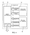
- FIG. 4 is a block diagram of a further exemplary embodiment of a tilt sensor unit according to the invention.
- FIG. 5 is a flow chart illustrating main steps of an exemplary mode of the method according to the invention.
- FIG. 6 is a flow chart illustrating main steps of a further mode of the method according to the invention.
- FIG. 1 illustrates the vehicle X-axis, the vehicle Y-axis and the vehicle Z-axis which are perpendicular with respect to one another.
- the X-axis is the longitudinal axis of the vehicle 10 .
- the Y-axis is the transverse axis of the vehicle 10 and the Z-axis is the vertical axis.
- Roll, pitch and yaw motions are defined as rotations about the X-axis, Y-axis, and Z-axis.
- the vehicle 10 has a tilt sensor unit 12 for determining roll and pitch information for the vehicle 10 .
- the tilt sensor unit 12 is connected to a display 14 which displays the roll and pitch information.
- FIG. 2 is a diagrammatic view of a display 14 which is provided in the vehicle 10 for presenting pitch and roll information to the driver of the vehicle 10 .
- the display 14 may be provided in an instrument cluster 15 of the vehicle 10 .
- the instrument cluster 15 of the vehicle 10 is only schematically indicated by a dashed line.
- the instrument cluster 15 may include a speedometer, an odometer and further displays for providing information for the driver.
- the display 14 has a pitch information indicator 16 and a roll information indicator 18 .
- the pitch information indicator 16 has the shape of a circular disk and shows a pictogram 11 of the vehicle 10 in a side view on a driving surface 20 .
- pitch angle indicator marks 24 are pitch angle indicator marks 24 .
- the circular disk Underneath the circular disk is a fixed indicator triangle 26 for indicating a pitch angle. Underneath the indicator triangle 26 is a numerical display 28 which displays the pitch angle in degrees.
- the roll information indicator 18 is shown as a circular disk with a pictogram 31 of the vehicle 10 on a driving surface 20 . Along the circumference of the lower portion of the roll information indicator 18 are roll angle indicator marks 44 . The pictogram 31 of the vehicle 10 on the driving surface 20 together with the roll indicator marks 44 rotate such that the roll angle of vehicle pictogram 31 shown in the roll information indicator 18 corresponds to the roll angle of the vehicle 10 .
- Underneath the circular disk Underneath the circular disk is a fixed indicator triangle 46 for indicating a roll angle. Underneath the indicator triangle 46 is a numerical display 48 which displays the roll angle in degrees.
- FIG. 3 shows a block diagram of an exemplary embodiment of a tilt sensor unit 12 according to the invention.
- the tilt sensor unit 12 shown in FIG. 3 operates as a magnitude-compensated tilt sensor as will be described in detail below.
- the tilt sensor unit 12 includes a tri-axial tilt sensor 50 as a sensing element.
- the tri-axial tilt sensor 50 is for example a single-chip tri-axial accelerometer.
- An example for such a tri-axial accelerometer is the accelerometer chip ADXL330, manufactured by ANALOG DEVICES, INC.
- the ADXL330 chip is a three-axis acceleration measurement device whose output signals are analog voltages that are proportional to measured accelerations.
- the accelerometer chip 50 can measure the static acceleration due to gravity as well as dynamic accelerations resulting from motion, shock, or vibration.
- the tri-axial tilt sensor 50 outputs analog voltages which are proportional to sensed accelerations along the X, Y, and Z axes.
- the tri-axial tilt sensor 50 would for example provide an output indicating that there is an acceleration of 1 G (acceleration of gravity) in a direction parallel to the Z-axis.
- the tilt sensor unit 12 further includes a microcontroller 52 which is connected to the tri-axial tilt sensor 50 such that the analog output voltages of the tri-axial tilt sensor 50 are fed directly to an analog-to-digital converter system which is preferably built within the microcontroller 52 .
- the microcontroller 52 is for example a C8051F040 microcontroller manufactured by SILICON LABORATORIES, INC.
- the C8051F040 microcontroller includes a 12-bit analog-to-digital converter system in order to convert the analog output voltages of the tri-axial tilt sensor 50 into digital signals to be processed by the microcontroller 52 .
- the microcontroller 52 is programmed in the programming language C in order to execute the equations described below and to output magnitude-compensated roll and pitch values.
- the magnitude-compensated roll and pitch values can be used to provide roll and pitch information on the display 14 in real-time.
- the tri-axial tilt sensor 50 is a tilt sensing element that is capable of reporting the roll and pitch of its mounting surface. Depending on the orientation of the mounting surface, the X, Y, and Z axes of the tilt sensor 50 may not be aligned with the X, Y, and Z axes of the vehicle 10 . Such a mechanical misalignment can be corrected in a calibration step.
- the tilt sensor 50 may be calibrated such that it will report a zero-degree roll and tilt in an arbitrary mounting orientation. This calibration step is an axes transformation from the relative X, Y, Z directions of the tilt sensor's orientation to the X, Y, Z axes of the vehicle 10 .
- the calibration step thus ensures that the tilt sensor provides pitch and roll information relative to the direction of gravity rather than the orientation of the mounting surface.
- the tilt sensor 50 and the control electronics including the microcontroller 52 can advantageously be constructed and assembled in an automated process using normal electronics fabrication procedures.
- the above-mentioned calibration step is preferably performed on the produced tilt sensor unit 12 in order to verify the accuracy of the tilt sensor unit 12 . Since the tilt sensor 50 cooperates with the microcontroller, any anomalies or deviations occurring during production can advantageously be repaired by programming changes.
- the main sensing element of the tilt sensor 50 preferably uses MEMS (Micro-Electro-Mechanical System) technology for integrating the acceleration sensors and electronic circuitry on a common silicon substrate.
- MEMS Micro-Electro-Mechanical System
- the sensing element and control electronics can be constructed and assembled in an automated process using normal electronics fabrication procedures.
- the tilt sensor unit 12 shown in FIG. 3 operates as a magnitude-compensated tilt sensor.
- the method to process tilt angles i.e. roll angles and pitch angles, requires a sensed magnitude of acceleration effects in the direction of the X, Y, and Z axes.
- a single-chip tri-axial accelerometer such as the tri-axial tilt sensor 50 may be used.
- a combination of dual-axis or single-axis accelerometers, which are mounted such that they are capable of measuring accelerations in the directions of the X, Y, and Z orthogonal axes may be used. In the embodiment shown in FIG.
- the sensor data generated by the tri-axial tilt sensor 50 are then fed into the microcontroller 52 for performing the magnitude compensation method described in the following.
- the microcontroller 52 used in the exemplary embodiment of the invention may be replaced by any computer or computational unit that can perform the method steps for providing magnitude-compensated tilt angles.
- the raw sensor data provided by the tri-axial tilt sensor 50 is assumed to be normalized to gravity, such that the accelerations in the direction of the X, Y, and Z axes, namely X_acceleration, Y_acceleration, and Z_acceleration, are in multiples or fractions of G, the acceleration due to gravity, wherein G is approximately 9.81 m/s 2 .
- the raw sensor data can be processed to compute the sensed roll and pitch of the tilt sensor unit 12 in an uncompensated format as expressed in the following equations:
- the variables Roll and YZ_angle designate the roll angle about the X-axis
- the variables Pitch and XZ_angle designate the pitch angle about the Y-axis.
- the variables X_acceleration, Y_acceleration, and Z_acceleration designate the accelerations in the X, Y, and Z axes in multiples of G.
- the function atan2 is the two-parameter function for computing the arctangent in programming languages such as the C programming language.
- the magnitude of the sensed acceleration of the uncompensated accelerations measured by the tri-axial tilt sensor 50 is the vector sum of the accelerations in the directions of the X, Y, and Z axes and is expressed in equation (3) below.
- Magnitude ⁇ square root over (( X _acceleration) 2 +( Y _acceleration) 2 +( Z _acceleration) 2 ) ⁇ square root over (( X _acceleration) 2 +( Y _acceleration) 2 +( Z _acceleration) 2 ) ⁇ square root over (( X _acceleration) 2 +( Y _acceleration) 2 +( Z _acceleration) 2 ) ⁇ (3)
- the magnitude of the force vector due to gravity, without external accelerations, would be equal to 1 G, i.e. 9.81 m/s 2 .
- the magnitude of the sensed resultant vector changes through superposition. This change of magnitude as defined in equation (4) can then be tracked for the purpose of introducing compensation.
- ⁇ Magnitude
- a tilt angle can be present in the form of a roll angle or a pitch angle or a combination of a roll and a pitch angle. In case such external forces act on the tri-axial tilt sensor 50 , it is preferable to discount the current sensor data in favor of the last known accurate values.
- a compensation factor is introduced for this purpose.
- the compensation factor is a number that has a value of less than 1 and decreases with an increased variance in magnitude.
- the compensation factor may be expressed by the following equation (5).
- the compensation factor defined in equation (5) is only exemplary and is not unique in fitting the above-mentioned criteria.
- the general concept of using a compensation factor is based on a reliance on past sensor data in the event of a change in magnitude of the sensed gravitational vector.
- the roll angle Roll(t) and the pitch angle Pitch(t) over time can then be computed with the following equations (6) and (7).
- Roll( t ) Roll( t ⁇ 1) ⁇ (1 ⁇ CompensationFactor)+ YZ _angle ⁇ (CompensationFactor) (6)
- Pitch( t ) Pitch( t ⁇ 1) ⁇ (1 ⁇ CompensationFactor)+ XZ _angle ⁇ (CompensationFactor) (7)
- the results of Roll(t) and Pitch(t) are the magnitude-compensated roll and pitch values of the tri-axial tilt sensor 50 .
- the calculation for compensation as defined by the above equations reports the last-known accurate sensor value in the event of a disturbance, which is the desired result in case of a disturbance.
- the above-defined method of calculation is suitable for low-cost embedded applications, as it does not require complex computation in real time.
- An advantage of the method of providing magnitude-compensated roll and pitch values in the manner described above is therefore the low cost when compared to gyroscopically compensated dynamic tilt sensors.
- a further advantage of the method of providing magnitude-compensated roll and pitch values is the ability to discern inaccurate sensor information and to introduce compensation.
- Another advantage of the above-defined calculation method is its high accuracy and precision in static situations and its resistance to dynamic disturbances.
- the method of providing magnitude-compensated roll and pitch values in the manner described above allows the introduction of a dynamic compensation in low-cost tilt sensor devices.
- a low-cost tilt sensor is used in combination with a magnitude compensation method for computing roll and pitch for real-time automotive applications.
- FIG. 4 shows a block diagram of an exemplary embodiment of a tilt sensor unit 12 with an additional gyroscopic stabilization according to the invention.
- a gyroscope is a device which senses angular speed, or rotation. By integrating an angular speed, the angle traversed by the tilt sensor can be measured.
- Such a method of integrating angular speed is accurate, but over time is subject to a drift which makes the gyroscopic sensor output unreliable without a fixed reference.
- a fixed reference can be provided by the magnitude-compensation tilt-sensing method as explained above with respect to equations (1) to (7).
- the tilt sensor unit 12 shown in FIG. 4 includes a tri-axial tilt sensor 50 .
- the tri-axial tilt sensor 50 in FIG. 4 is for example a single-chip tri-axial accelerometer such as the accelerometer chip ADXL330, manufactured by ANALOG DEVICES, INC.
- the tri-axial tilt sensor 50 outputs analog voltages which are proportional to sensed accelerations in the directions along the X, Y, and Z axes.
- the tilt sensor unit 12 of FIG. 4 further includes a microcontroller 52 which is connected to the tri-axial tilt sensor 50 such that the analog output voltages of the tri-axial tilt sensor 50 are fed directly to an analog-to-digital converter system which is preferably built within the microcontroller 52 .
- the microcontroller 52 is for example a C8051F040 microcontroller manufactured by SILICON LABORATORIES, INC.
- the C8051F040 microcontroller includes a 12-bit analog-to-digital converter system in order to convert the analog output voltages of the tri-axial tilt sensor 50 into digital signals to be processed by the microcontroller 52 .
- the tilt sensor unit 12 further includes a dual-axis gyroscope 54 which is connected to the microcontroller 52 .
- the dual-axis gyroscope 54 provides angular rate data for a rotation about the X-axis and angular rate data for a rotation about the Y-axis.
- the output of the dual-axis gyroscope 54 are for example voltages that are proportional to the angular rates of the rotation about the X-axis and the Y-axis. These output voltages are then converted to a digital signal by an analog-to-digital converter system within the microcontroller 52 .
- the dual-axis gyroscope 54 may include an analog-to-digital converter and provide the angular rates in the form of a digital signal.
- the tri-axial tilt sensor is capable of reporting the roll and pitch of its mounting surface.
- the tilt sensor 50 is calibrated such that it will report a zero-degree roll and tilt when it is positioned in its mounting orientation.
- This calibration step is an axes transformation from the relative X, Y, Z directions of the tilt sensor's orientation to the X, Y, Z axes of the vehicle 10 .
- the calibration step ensures that the tilt sensor provides pitch and roll information relative to the direction of gravity rather than the orientation of the mounting surface.
- the calibration step is preferably performed on the produced tilt sensor unit 12 in order to verify the accuracy of the tilt sensor unit 12 .
- a correction of anomalies or deviations is preferably performed by programming changes.
- tilt sensor units include roll over detection for vehicles, augmentation of navigation information with a display of vehicle roll and pitch, hill descent/ascent control with electronic braking, suspension leveling feedback, parking brake force modulation assist, anti-theft systems, vehicle stability information, vibration detection, high accuracy static tilt sensing, road-grade detection for safety electronics.
- magnitude-compensated tilt sensors include real-time display of roll and tilt information in a vehicle which increases driver awareness of the vehicle state and provides enjoyable metric for off-road enthusiasts.
- the gyroscope data can be utilized by measuring a time period ⁇ Time, which can be computed by the system clock of the microcontroller 52 .
- ⁇ Time the time period
- the change in tilt angle over a time period can be calculated by the following equations.
- ARoll(t) and XGyroIntegral denote a change in the roll angle during a time interval ⁇ Time.
- XGyroMeasurement(t) and XGyroMeasurement(t ⁇ 1) are the gyroscope measurement data at the time t and, respectively, at the time t ⁇ 1 for a roll motion about the X-axis of the vehicle 10 .
- ⁇ Pitch(t) and YGyroIntegral denote a change in the pitch angle during a time interval ⁇ Time.
- YGyroMeasurement(t) and YGyroMeasurement(t ⁇ 1) are the gyroscope measurement data at the time t and, respectively, at the time t ⁇ 1 for a pitch motion about the Y-axis of the vehicle 10 .
- the measured changes in the roll and pitch value as defined in equations (8) and (9) can be included in the final computation by updating the value to which the tilt sensor unit 12 defaults on inaccurate accelerometer information.
- the resulting gyroscopically stabilized magnitude compensation equations are defined in the following manner.
- Roll( t ) (Roll( t ⁇ 1)+XGyroIntegral) ⁇ (1 ⁇ CompensationFactor)+ YZ _angle ⁇ (CompensationFactor) (10)
- Pitch( t ) (Pitch( t ⁇ 1)+YGyroIntegral) ⁇ (1 ⁇ CompensationFactor)+ XZ _angle ⁇ (CompensationFactor) (11)
- the result of the above gyroscopically stabilized magnitude compensation equations (10) and (11) is an accurate estimate of actual sensor roll and pitch angles measured from a gravitational reference.
- the method described above relies on a highly accurate accelerometer in the form of the tri-axial tilt sensor 50 .
- the tilt sensor unit 12 shown in FIG. 4 relies on the gyroscope data provided by the dual-axis gyroscope 54 and continually updates the output in dependence on the gyroscope data.
- FIG. 5 is a flow chart illustrating main steps of an exemplary mode of the method according to the invention.
- the order of the steps shown in FIGS. 5 and 6 is only exemplary because the calculation steps can be performed in a different order and at least some of the calculation steps could be performed substantially simultaneously.
- step 60 accelerations of the vehicle 10 are measured in directions along the X-axis, the Y-axis, and the Z-axis by using the tri-axial tilt sensor 50 .
- step 62 a current roll angle and a current pitch angle of the vehicle 10 are calculated as a function of the measured accelerations in accordance with equations (1) and (2).
- step 64 the magnitude of the vector sum of the accelerations of the vehicle 10 in the directions along the X-axis, the Y-axis, and the Z-axis is calculated in accordance with equation (3).
- step 66 the magnitude-compensated roll angle is calculated as a function of the current roll angle, of a preceding roll angle and of the magnitude of the vector sum of the measured accelerations in the directions along the X-axis, the Y-axis, and the Z-axis in accordance with equation (6).
- the magnitude-compensated pitch angle is calculated as a function of the current pitch angle, of a preceding pitch angle and of the magnitude of the vector sum of the measured accelerations in the directions along the X-axis, the Y-axis, and the Z-axis in accordance with equation (7).
- FIG. 6 is a flow chart illustrating main steps of a further exemplary mode of the method according to the invention.
- step 70 accelerations of the vehicle 10 in directions along an X-axis, a Y-axis, and a Z-axis are measured by using the tri-axial tilt sensor 50 .
- step 72 angular rates are measured with the dual-axis gyroscope 54 .
- step 74 a current roll angle and a current pitch angle of the vehicle are calculated as a function of the measured accelerations in accordance with equations (1) and (2).
- step 76 a change in the roll angle and a change in the pitch angle over a given time period are calculated by using the angular rate data from the dual-axis gyroscope 54 in accordance with equations (8) and (9).
- step 78 the magnitude of the vector sum of the accelerations of the vehicle 10 in the directions along the X-axis, the Y-axis, and the Z-axis is calculated in accordance with equation (3).
- step 80 the gyroscopically stabilized magnitude-compensated roll angle is calculated as a function of the current roll angle calculated from the acceleration measurement values, of a preceding roll angle, of the magnitude of the vector sum of the accelerations in the directions along the X-axis, the Y-axis, and the Z-axis, and of the change in the roll angle over the given time period calculated from the angular rate data in accordance with equation (10).
- the gyroscopically stabilized magnitude-compensated pitch angle is calculated as a function of the current pitch angle calculated from the acceleration measurement values, of a preceding pitch angle, of the magnitude of the vector sum of the accelerations in the directions along the X-axis, the Y-axis, and the Z-axis, and of the change in the pitch angle over the given time period calculated from the angular rate data in accordance with equation (11).
Landscapes
- Engineering & Computer Science (AREA)
- Mechanical Engineering (AREA)
- Transportation (AREA)
- Automation & Control Theory (AREA)
- Physics & Mathematics (AREA)
- General Physics & Mathematics (AREA)
- Mathematical Physics (AREA)
- Radar, Positioning & Navigation (AREA)
- Remote Sensing (AREA)
- Chemical & Material Sciences (AREA)
- Combustion & Propulsion (AREA)
- Human Computer Interaction (AREA)
- Gyroscopes (AREA)
Priority Applications (2)
| Application Number | Priority Date | Filing Date | Title |
|---|---|---|---|
| US11/821,318 US7463953B1 (en) | 2007-06-22 | 2007-06-22 | Method for determining a tilt angle of a vehicle |
| DE102008027087.3A DE102008027087B4 (de) | 2007-06-22 | 2008-06-05 | Verfahren zum Bestimmen eines Neigungswinkels eines Fahrzeugs |
Applications Claiming Priority (1)
| Application Number | Priority Date | Filing Date | Title |
|---|---|---|---|
| US11/821,318 US7463953B1 (en) | 2007-06-22 | 2007-06-22 | Method for determining a tilt angle of a vehicle |
Publications (2)
| Publication Number | Publication Date |
|---|---|
| US7463953B1 true US7463953B1 (en) | 2008-12-09 |
| US20080319589A1 US20080319589A1 (en) | 2008-12-25 |
Family
ID=40031009
Family Applications (1)
| Application Number | Title | Priority Date | Filing Date |
|---|---|---|---|
| US11/821,318 Active US7463953B1 (en) | 2007-06-22 | 2007-06-22 | Method for determining a tilt angle of a vehicle |
Country Status (2)
| Country | Link |
|---|---|
| US (1) | US7463953B1 (de) |
| DE (1) | DE102008027087B4 (de) |
Cited By (20)
| Publication number | Priority date | Publication date | Assignee | Title |
|---|---|---|---|---|
| US20090164060A1 (en) * | 2007-02-19 | 2009-06-25 | Solidica, Inc. | Vehicle instability detection and prevention system |
| US20090204351A1 (en) * | 2005-08-18 | 2009-08-13 | Yasuhiro Tamura | Sensor Apparatus |
| US20100185354A1 (en) * | 2009-01-21 | 2010-07-22 | Raytheon Company | Dynamic Rollover Prevention |
| US20100256857A1 (en) * | 2007-11-09 | 2010-10-07 | Thinkware Systems Corporation | Apparatus and method for deciding travel condition of vehicle |
| US20120158239A1 (en) * | 2009-07-06 | 2012-06-21 | Renault S.A.S. | Method and device for monitoring that a vehicle in standby mode is correctly immobilized for transport, and vehicle equipped with such a device |
| US20120190404A1 (en) * | 2008-08-19 | 2012-07-26 | Rhoads Geoffrey B | Methods and Systems for Content Processing |
| ITTO20120909A1 (it) * | 2012-10-16 | 2014-04-17 | Selex Galileo Spa | Innovativo sistema di visione esterna e/o di puntamento di un'arma per veicoli militari terrestri equipaggiati con almeno un'arma |
| WO2014186786A1 (en) * | 2013-05-17 | 2014-11-20 | Honda Motor Co., Ltd. | Localization using road markings |
| US20150160258A1 (en) * | 2013-12-05 | 2015-06-11 | Huawei Device Co., Ltd. | Method and Apparatus for Determining Vehicle Acceleration |
| US20160161944A1 (en) * | 2014-12-05 | 2016-06-09 | Charles A. Leonard | Vehicle leveling systems, devices and methods and computer program products for leveling vehicles using smart devices |
| CN107478312A (zh) * | 2017-10-17 | 2017-12-15 | 山东交通学院 | 一种动静两用货车称重系统及称重方法 |
| US20170361847A1 (en) * | 2016-06-21 | 2017-12-21 | Mazda Motor Corporation | Control system of a four-wheel drive vehicle and gradient value setting device of a vehicle |
| US10316959B2 (en) | 2016-01-29 | 2019-06-11 | Cnh Industrial America Llc | System and method for controlling a work vehicle transmission based on the detection of unintended vehicle motion |
| US11001152B2 (en) * | 2018-09-26 | 2021-05-11 | GM Global Technology Operations LLC | Powertrain architectures and control algorithms for intelligent electric scooters |
| US11414834B2 (en) * | 2017-10-27 | 2022-08-16 | Kobelco Construction Machinery Co., Ltd. | Travel route guidance device |
| CN114966889A (zh) * | 2022-05-24 | 2022-08-30 | 中国科学院西安光学精密机械研究所 | 一种机载稳定平台稳定精度检测装置及其测试方法 |
| CN114964120A (zh) * | 2022-02-10 | 2022-08-30 | 贵州大学 | 基于角度信息解耦的旋转检测框表达方式的系统 |
| US11543281B1 (en) * | 2018-10-15 | 2023-01-03 | Brian E. Lipscomb | Fluid level sensing systems, method, and apparatus |
| US20230077116A1 (en) * | 2021-09-09 | 2023-03-09 | Hyundai Motor Company | Method for determining driving status of vehicle |
| US11619489B2 (en) | 2020-04-16 | 2023-04-04 | Volkswagen Aktiengesellschaft | Method for visualizing an inclination of a motor vehicle in the motor vehicle |
Families Citing this family (18)
| Publication number | Priority date | Publication date | Assignee | Title |
|---|---|---|---|---|
| US9945753B2 (en) * | 2009-01-13 | 2018-04-17 | United Aeronautical Corp. | Cargo loading trailer |
| US8589015B2 (en) * | 2010-02-12 | 2013-11-19 | Webtech Wireless Inc. | Vehicle sensor calibration for determining vehicle dynamics |
| US9043041B2 (en) * | 2010-02-12 | 2015-05-26 | Webtech Wireless Inc. | Monitoring aggressive driving operation of a mobile asset |
| DE102010041967A1 (de) * | 2010-10-05 | 2012-04-05 | Zf Friedrichshafen Ag | Verfahren zum Ermitteln einer Neigung eines Fahrzeuges in Fahrtrichtung |
| USRE49776E1 (en) * | 2010-10-26 | 2024-01-02 | Koito Manufacturing Co., Ltd. | Vehicle lamp controller, vehicle lamp system, and vehicle lamp control method |
| US8548722B2 (en) * | 2011-08-12 | 2013-10-01 | Deere & Company | Tilt sensor and method for determining the tilt of a vehicle |
| US9145144B2 (en) * | 2011-09-28 | 2015-09-29 | Caterpillar Inc. | Inclination detection systems and methods |
| US9193407B2 (en) | 2012-08-21 | 2015-11-24 | John Austin Muth | Active downforce generation for a tilting vehicle |
| DE102013226128A1 (de) * | 2013-12-16 | 2015-06-18 | Continental Teves Ag & Co. Ohg | Adaptive Unterstützung beim Öffnen einer Fahrzeugtür |
| DE102014206049A1 (de) | 2014-03-31 | 2015-10-01 | Volkswagen Aktiengesellschaft | Verfahren zum Anzeigen von Informationen in einem Fahrzeug |
| DE102015210887B4 (de) | 2015-02-26 | 2017-04-06 | Volkswagen Aktiengesellschaft | Verfahren und Vorrichtung zum Anzeigen einer Beschleunigung in einem Fahrzeug |
| US10730510B2 (en) | 2016-03-04 | 2020-08-04 | Rtms Pty Limited | Apparatus and method for sensing tilt of an object |
| CN107781107B (zh) * | 2016-08-31 | 2019-04-16 | 新疆金风科技股份有限公司 | 风电机组最优桨距角自适应寻优控制方法、装置和设备 |
| DE102017001271B3 (de) | 2017-02-10 | 2018-01-11 | HTW Hochschule für Technik und Wirtschaft Dresden | System und Verfahren zur Bestimmung eines Nickwinkels eines Fahrzeugs |
| WO2019172461A1 (ko) * | 2018-03-06 | 2019-09-12 | 주식회사 선택인터내셔날 | 차량의 움직임을 측정하기 위한 실시간 가속도 센서 보정 장치 및 이를 이용한 가속도 센서 보정 방법 |
| DE102018204409A1 (de) * | 2018-03-22 | 2019-09-26 | Volkswagen Aktiengesellschaft | Verfahren zum Anzeigen von den Betrieb eines Fahrzeugs betreffende Informationen und Anzeigesystem |
| DE102019203975A1 (de) | 2018-04-16 | 2019-10-17 | Continental Automotive Gmbh | Verfahren zur Bestimmung eines Roll- und/oder Nickwinkels eines Fahrzeugs |
| CN113085875B (zh) * | 2021-03-23 | 2022-12-27 | 浙江吉利控股集团有限公司 | 基于俯仰角与纵向坡度角确定纵向加速度方法及装置 |
Citations (12)
| Publication number | Priority date | Publication date | Assignee | Title |
|---|---|---|---|---|
| DE19732081A1 (de) | 1997-07-25 | 1999-01-28 | Bosch Gmbh Robert | Verfahren und Anordnung zum Ermitteln der Inertiallage eines Fahrzeugs |
| US6178375B1 (en) | 1997-10-06 | 2001-01-23 | Robert Bosch Gmbh | Method and device for determining the inertial position of a vehicle |
| US20020022924A1 (en) | 2000-03-07 | 2002-02-21 | Begin John David | Propagation of position with multiaxis accelerometer |
| US6399941B1 (en) | 1997-12-02 | 2002-06-04 | Matsushita Electric Industrial, Co., Ltd. | Inclination angle sensor |
| EP0769701B1 (de) | 1995-10-17 | 2002-08-07 | Continental Teves AG & Co. oHG | Vorrichtung zur Erfassung einer Fahrzeugquerneigung |
| US6516665B1 (en) | 1999-06-17 | 2003-02-11 | The Penn State Research Foundation | Micro-electro-mechanical gyroscope |
| JP2003065793A (ja) | 2001-08-22 | 2003-03-05 | Japan Aviation Electronics Industry Ltd | 慣性装置 |
| US6634113B1 (en) | 2002-05-17 | 2003-10-21 | Delphi Technologies, Inc. | Tilt sensor and method of forming such device |
| US6856884B2 (en) | 2002-03-06 | 2005-02-15 | Chadwick Ray Traylor | Accelerometer gauge using solid state accelerometers |
| US20050256675A1 (en) | 2002-08-28 | 2005-11-17 | Sony Corporation | Method and device for head tracking |
| US7408453B2 (en) * | 2001-02-16 | 2008-08-05 | Automotive Technologies International, Inc. | Wheel-mounted tire pumping and energy generating system and method |
| US7421321B2 (en) * | 1995-06-07 | 2008-09-02 | Automotive Technologies International, Inc. | System for obtaining vehicular information |
Family Cites Families (1)
| Publication number | Priority date | Publication date | Assignee | Title |
|---|---|---|---|---|
| US6600985B2 (en) * | 2001-03-26 | 2003-07-29 | Indiana Mills & Manufacturing, Inc. | Roll sensor system for a vehicle |
-
2007
- 2007-06-22 US US11/821,318 patent/US7463953B1/en active Active
-
2008
- 2008-06-05 DE DE102008027087.3A patent/DE102008027087B4/de active Active
Patent Citations (14)
| Publication number | Priority date | Publication date | Assignee | Title |
|---|---|---|---|---|
| US7421321B2 (en) * | 1995-06-07 | 2008-09-02 | Automotive Technologies International, Inc. | System for obtaining vehicular information |
| EP0769701B1 (de) | 1995-10-17 | 2002-08-07 | Continental Teves AG & Co. oHG | Vorrichtung zur Erfassung einer Fahrzeugquerneigung |
| US6259999B1 (en) | 1997-07-25 | 2001-07-10 | Robert Bosch Gmbh | Method and device for determining a vehicle inertial position |
| DE19732081A1 (de) | 1997-07-25 | 1999-01-28 | Bosch Gmbh Robert | Verfahren und Anordnung zum Ermitteln der Inertiallage eines Fahrzeugs |
| EP0928258B1 (de) | 1997-07-25 | 2002-02-27 | Robert Bosch Gmbh | Verfahren und anordnung zum ermitteln der inertiallage eines fahrzeugs |
| US6178375B1 (en) | 1997-10-06 | 2001-01-23 | Robert Bosch Gmbh | Method and device for determining the inertial position of a vehicle |
| US6399941B1 (en) | 1997-12-02 | 2002-06-04 | Matsushita Electric Industrial, Co., Ltd. | Inclination angle sensor |
| US6516665B1 (en) | 1999-06-17 | 2003-02-11 | The Penn State Research Foundation | Micro-electro-mechanical gyroscope |
| US20020022924A1 (en) | 2000-03-07 | 2002-02-21 | Begin John David | Propagation of position with multiaxis accelerometer |
| US7408453B2 (en) * | 2001-02-16 | 2008-08-05 | Automotive Technologies International, Inc. | Wheel-mounted tire pumping and energy generating system and method |
| JP2003065793A (ja) | 2001-08-22 | 2003-03-05 | Japan Aviation Electronics Industry Ltd | 慣性装置 |
| US6856884B2 (en) | 2002-03-06 | 2005-02-15 | Chadwick Ray Traylor | Accelerometer gauge using solid state accelerometers |
| US6634113B1 (en) | 2002-05-17 | 2003-10-21 | Delphi Technologies, Inc. | Tilt sensor and method of forming such device |
| US20050256675A1 (en) | 2002-08-28 | 2005-11-17 | Sony Corporation | Method and device for head tracking |
Cited By (30)
| Publication number | Priority date | Publication date | Assignee | Title |
|---|---|---|---|---|
| US20090204351A1 (en) * | 2005-08-18 | 2009-08-13 | Yasuhiro Tamura | Sensor Apparatus |
| US20090164060A1 (en) * | 2007-02-19 | 2009-06-25 | Solidica, Inc. | Vehicle instability detection and prevention system |
| US8948924B2 (en) * | 2007-11-09 | 2015-02-03 | Thinkware Systems Corporation | Apparatus and method for deciding travel condition of vehicle |
| US20100256857A1 (en) * | 2007-11-09 | 2010-10-07 | Thinkware Systems Corporation | Apparatus and method for deciding travel condition of vehicle |
| US20120190404A1 (en) * | 2008-08-19 | 2012-07-26 | Rhoads Geoffrey B | Methods and Systems for Content Processing |
| US20100185354A1 (en) * | 2009-01-21 | 2010-07-22 | Raytheon Company | Dynamic Rollover Prevention |
| US8095269B2 (en) | 2009-01-21 | 2012-01-10 | Raytheon Company | Dynamic rollover prevention |
| US20120158239A1 (en) * | 2009-07-06 | 2012-06-21 | Renault S.A.S. | Method and device for monitoring that a vehicle in standby mode is correctly immobilized for transport, and vehicle equipped with such a device |
| US8688310B2 (en) * | 2009-07-06 | 2014-04-01 | Renault S.A.S. | Method and device for monitoring that a vehicle in standby mode is correctly immobilized for transport, and vehicle equipped with such a device |
| ITTO20120909A1 (it) * | 2012-10-16 | 2014-04-17 | Selex Galileo Spa | Innovativo sistema di visione esterna e/o di puntamento di un'arma per veicoli militari terrestri equipaggiati con almeno un'arma |
| WO2014060971A1 (en) * | 2012-10-16 | 2014-04-24 | Selex Es S.P.A. | Innovative external vision and/or weapon aiming system for military land vehicles equipped with at least one weapon |
| US9488483B2 (en) | 2013-05-17 | 2016-11-08 | Honda Motor Co., Ltd. | Localization using road markings |
| WO2014186786A1 (en) * | 2013-05-17 | 2014-11-20 | Honda Motor Co., Ltd. | Localization using road markings |
| US9817022B2 (en) * | 2013-12-05 | 2017-11-14 | Huawei Device Co., Ltd. | Method and apparatus for determining vehicle acceleration |
| US20150160258A1 (en) * | 2013-12-05 | 2015-06-11 | Huawei Device Co., Ltd. | Method and Apparatus for Determining Vehicle Acceleration |
| US20160161944A1 (en) * | 2014-12-05 | 2016-06-09 | Charles A. Leonard | Vehicle leveling systems, devices and methods and computer program products for leveling vehicles using smart devices |
| US10316959B2 (en) | 2016-01-29 | 2019-06-11 | Cnh Industrial America Llc | System and method for controlling a work vehicle transmission based on the detection of unintended vehicle motion |
| US20170361847A1 (en) * | 2016-06-21 | 2017-12-21 | Mazda Motor Corporation | Control system of a four-wheel drive vehicle and gradient value setting device of a vehicle |
| US10464545B2 (en) * | 2016-06-21 | 2019-11-05 | Mazda Motor Corporation | Control system of a four-wheel drive vehicle and gradient value setting device of a vehicle |
| CN107478312B (zh) * | 2017-10-17 | 2023-08-22 | 山东交通学院 | 一种动静两用货车称重系统及称重方法 |
| CN107478312A (zh) * | 2017-10-17 | 2017-12-15 | 山东交通学院 | 一种动静两用货车称重系统及称重方法 |
| US11414834B2 (en) * | 2017-10-27 | 2022-08-16 | Kobelco Construction Machinery Co., Ltd. | Travel route guidance device |
| US11001152B2 (en) * | 2018-09-26 | 2021-05-11 | GM Global Technology Operations LLC | Powertrain architectures and control algorithms for intelligent electric scooters |
| US11543281B1 (en) * | 2018-10-15 | 2023-01-03 | Brian E. Lipscomb | Fluid level sensing systems, method, and apparatus |
| US11619489B2 (en) | 2020-04-16 | 2023-04-04 | Volkswagen Aktiengesellschaft | Method for visualizing an inclination of a motor vehicle in the motor vehicle |
| US20230077116A1 (en) * | 2021-09-09 | 2023-03-09 | Hyundai Motor Company | Method for determining driving status of vehicle |
| CN114964120A (zh) * | 2022-02-10 | 2022-08-30 | 贵州大学 | 基于角度信息解耦的旋转检测框表达方式的系统 |
| CN114964120B (zh) * | 2022-02-10 | 2024-05-31 | 贵州大学 | 基于角度信息解耦的旋转检测框表达方式的系统 |
| CN114966889A (zh) * | 2022-05-24 | 2022-08-30 | 中国科学院西安光学精密机械研究所 | 一种机载稳定平台稳定精度检测装置及其测试方法 |
| CN114966889B (zh) * | 2022-05-24 | 2024-04-12 | 中国科学院西安光学精密机械研究所 | 一种机载稳定平台稳定精度检测装置及其测试方法 |
Also Published As
| Publication number | Publication date |
|---|---|
| DE102008027087A1 (de) | 2008-12-24 |
| DE102008027087B4 (de) | 2020-04-16 |
| US20080319589A1 (en) | 2008-12-25 |
Similar Documents
| Publication | Publication Date | Title |
|---|---|---|
| US7463953B1 (en) | Method for determining a tilt angle of a vehicle | |
| CN110221333B (zh) | 一种车载ins/od组合导航系统的量测误差补偿方法 | |
| US8249800B2 (en) | Method and apparatus to detect platform stationary status using three-axis accelerometer outputs | |
| JP3375268B2 (ja) | ナビゲーション装置 | |
| CN111678538B (zh) | 一种基于速度匹配的动态水平仪误差补偿方法 | |
| JP7073052B2 (ja) | ビークルの角度位置を測定するシステムおよび方法 | |
| EP1722239B1 (de) | Verfahren und Vorrichtung zur Messung der Geschwindigkeit eines beweglichen Objekts | |
| CN107588769B (zh) | 一种车载捷联惯导、里程计及高程计组合导航方法 | |
| CN201561759U (zh) | 惯性姿态方位测量装置 | |
| CN103206965B (zh) | 车辆用陀螺仪的角速度误差修正装置、修正方法 | |
| CN101290229A (zh) | 硅微航姿系统惯性/地磁组合方法 | |
| CN106153069B (zh) | 自主导航系统中的姿态修正装置和方法 | |
| AU2015305864B2 (en) | Earthmoving machine comprising weighted state estimator | |
| CN106403952A (zh) | 一种动中通低成本组合姿态测量方法 | |
| JP2021179438A (ja) | 機首方位測定システムにおけるセンサ測定の欠如を補償するシステムと方法 | |
| JP2021518529A (ja) | 車両に装備されたジャイロメータの較正方法 | |
| KR100520144B1 (ko) | 가속도계를 이용한 이동체의 속력측정 및 그 장치 | |
| JP4149913B2 (ja) | 慣性オドメータ補正による統合慣性vms航法 | |
| CN112429006A (zh) | 车载式路面坡度测量系统及测量方法 | |
| US9791277B2 (en) | Apparatus and method for measuring velocity of moving object in a navigation system | |
| CN109596139B (zh) | 基于mems的车载导航方法 | |
| JP3783061B1 (ja) | 傾斜角と並進加速度の検出方法および検出装置 | |
| WO2018012064A1 (ja) | 角度計測装置 | |
| CN114152269B (zh) | 车轮安装惯性测量单元的安装参数现场标定方法 | |
| JPH0643516U (ja) | 位置検出装置 |
Legal Events
| Date | Code | Title | Description |
|---|---|---|---|
| AS | Assignment |
Owner name: VOLKSWAGEN AG, GERMANY Free format text: ASSIGNMENT OF ASSIGNORS INTEREST;ASSIGNORS:LEE, JONATHAN;ROSARIO, DANIEL;STOSCHEK, ARNE;AND OTHERS;REEL/FRAME:021786/0061;SIGNING DATES FROM 20070430 TO 20070516 Owner name: VOLKSWAGEN OF AMERICA, INC., MICHIGAN Free format text: ASSIGNMENT OF ASSIGNORS INTEREST;ASSIGNORS:LEE, JONATHAN;ROSARIO, DANIEL;STOSCHEK, ARNE;AND OTHERS;REEL/FRAME:021786/0061;SIGNING DATES FROM 20070430 TO 20070516 |
|
| STCF | Information on status: patent grant |
Free format text: PATENTED CASE |
|
| FPAY | Fee payment |
Year of fee payment: 4 |
|
| FPAY | Fee payment |
Year of fee payment: 8 |
|
| MAFP | Maintenance fee payment |
Free format text: PAYMENT OF MAINTENANCE FEE, 12TH YEAR, LARGE ENTITY (ORIGINAL EVENT CODE: M1553); ENTITY STATUS OF PATENT OWNER: LARGE ENTITY Year of fee payment: 12 |