US7433205B2 - Supporting device for busbars in cabinets for electrical switchboards - Google Patents
Supporting device for busbars in cabinets for electrical switchboards Download PDFInfo
- Publication number
- US7433205B2 US7433205B2 US11/013,806 US1380604A US7433205B2 US 7433205 B2 US7433205 B2 US 7433205B2 US 1380604 A US1380604 A US 1380604A US 7433205 B2 US7433205 B2 US 7433205B2
- Authority
- US
- United States
- Prior art keywords
- wall
- seat
- module
- shaped
- coupling
- Prior art date
- Legal status (The legal status is an assumption and is not a legal conclusion. Google has not performed a legal analysis and makes no representation as to the accuracy of the status listed.)
- Expired - Fee Related, expires
Links
Images



Classifications
-
- H—ELECTRICITY
- H02—GENERATION; CONVERSION OR DISTRIBUTION OF ELECTRIC POWER
- H02G—INSTALLATION OF ELECTRIC CABLES OR LINES, OR OF COMBINED OPTICAL AND ELECTRIC CABLES OR LINES
- H02G5/00—Installations of bus-bars
- H02G5/02—Open installations
- H02G5/025—Supporting structures
Definitions
- the present invention relates to a supporting device for busbars in a cabinet for an electrical switchboard, said device having improved functions and characteristics.
- the bars are coupled geometrically to purposely designed devices that support the bars, insulating them electrically from one another, and enable their connection to the more resistant frame of the cabinet.
- said devices also enable the possible electrodynamic stresses produced by the flow of current in the bars to be discharged on the frame.
- the primary task of the present invention is to provide a supporting device for busbars in a cabinet for an electrical switchboard, which will enable the drawbacks referred to above to be overcome, and in particular which, as compared to the devices of a known type, will enable a number of configurations to be obtained, so increasing the flexibility of application.
- a purpose of the present invention is to provide a supporting device for busbars in a cabinet for an electrical switchboard, the structure of which may be obtained with an optimized number of parts that can be fitted to one another in a simplified way as compared to the devices of a known type.
- Another purpose of the present invention is to provide a supporting device for busbars in a cabinet for an electrical switchboard that is suited to a simplified assembly with the bars, as well as to fixing to the supporting structure, thus simplifying and reducing the installation steps and times.
- Not the least important purpose of the present invention is to provide a supporting device for busbars in a cabinet for an electrical switchboard that will present high reliability and be relatively easy to manufacture at competitive costs.
- a supporting device for busbars in a cabinet for an electrical switchboard comprising at least one first module having a shaped body designed to be connected to a supporting element of the cabinet, said first module being made substantially of electrically insulating material and having a first wall designed to be set resting on said supporting element and a second wall, along which there is defined at least one first coupling seat.
- the device according to the invention is characterized in that it comprises at least one second module having a shaped body made substantially of electrically insulating material having a third wall, along which there is defined at least one second coupling seat, and a fourth wall, along which there is defined at least one third coupling seat, said second module being operatively coupleable to said first module alternatively with said third or said fourth wall facing said second wall so that said first seat mates geometrically with said second or said third seat, so forming a seat for housing a busbar.
- FIGS. 1 and 2 are perspective views illustrating two modules of the device according to the invention.
- FIG. 3 is a perspective view illustrating the device according to the invention with the two modules of FIGS. 1 and 2 coupled, in a first embodiment
- FIG. 4 is a perspective view illustrating the device according to the invention with the two modules coupled, in a second embodiment
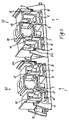
- FIG. 5 is a perspective view illustrating a further embodiment of the device according to the invention.
- FIG. 6 is a schematic representation of the device according to the invention coupled to a system of bars within a cabinet for an electrical switchboard.
- the supporting device for busbars comprises at least one first module 1 , designed to be connected to a supporting element, typically one of the elements making up the cabinet 100 of an electrical switchboard, for example a cross member 60 schematically illustrated in FIG. 5 , and at least one second module 10 that is to be coupled to the first module 1 according to the modalities that will be described in detail in what follows.
- the first module 1 has a shaped body made substantially of electrically insulating material, for example thermoplastic or thermosetting material, and has a first wall or face 2 , designed to be set resting on the supporting element 60 , and a second wall or face 3 , along which there is defined at least one first coupling seat 4 .
- the second module 10 also has a shaped body made substantially of electrically insulating material, for example thermoplastic or thermosetting material, and has a third wall or face 11 , along which there is defined at least one second coupling seat 12 , and a fourth wall or face 13 , along which there is defined at least one third coupling seat 14 .
- the two modules 1 and 10 are shaped so that the second module 10 is operatively coupleable to the first module 1 or alternatively to the third wall 11 ( FIG. 3 ) or to the fourth wall 13 ( FIG. 4 ) facing the second wall 3 so that the first seat 4 (and corresponding boundary walls) mates geometrically with the second seat 12 (and corresponding walls) or the third seat 14 (and corresponding walls), so forming a seat for housing a busbar.
- a further fourth coupling seat 5 on the second wall 3 there is defined a further fourth coupling seat 5 , with the two seats 4 and 5 that are arranged substantially symmetrical to one another with respect to an imaginary middle plane of the first module 1 perpendicular to the second wall 3 , designated for reasons of clarity of description in FIG. 1 by the reference number 40 .
- the two seats 4 and 5 have a U-shaped profile.
- the two seats could be differently configured, or else arranged along the wall 3 in different positions with respect to one another.
- both the two seats 12 and 15 defined on the wall 11 and the two seats 14 and 16 are arranged along the two corresponding walls 11 and 13 and are shaped so that, in the step of coupling of the two modules 1 and 10 , each of them can be geometrically mated alternatively either with the first seat 4 or with the second seat 5 , so forming in pairs two seats for housing two corresponding bars, as illustrated, for example, in FIGS. 3 and 4 .
- FIG. 1 in the embodiment illustrated in FIG.
- the four seats 12 , 14 , 15 and 16 have a U-shaped profile with the two branches of the U of lengths different from one another and profiles set two ( 12 / 14 ) by two ( 15 / 16 ) upside down with respect to one another.
- the four seats 12 , 14 , 15 and 16 have a U-shaped profile with the two branches of the U of lengths different from one another and profiles set two ( 12 / 14 ) by two ( 15 / 16 ) upside down with respect to one another.
- different alternatives are possible according to the needs of application, both as regards the configuration and as regards the mutual positioning.
- the two modules 1 and 10 are moreover shaped so as to present on their respective body geometrical coupling means that enable a direct reciprocal structural connection thereof, according to positions with respect to one another predefined according to desired configurations.
- the coupling means comprise first, second, and third means of connection defined, respectively, on the second wall 3 , on the third wall 11 , and on the fourth wall 13 , and are configured so that the first means of connection will be coupleable alternatively to the second means of connection or the third means of connection.
- the first means of connection comprise at least one first step-shaped surface 6 and one first tooth 7 , defined at the sides of the first seat 4 on sides opposite to one another in a position corresponding to the two edges of the first seat.
- the first means of connection moreover comprise a second step-shaped surface 8 and a second tooth 9 arranged at the sides of the fourth seat 5 on sides opposite to one another, with the first step-like surface 6 and the second step-like surface 8 that are arranged at the two ends of the second wall 3 symmetrically to one another with respect to the middle plane 40 .
- the two teeth 7 and 9 are arranged preferably symmetrical to one another with respect to the middle plane 40 .
- the second means of connection comprise at least one third step-shaped surface 17 , defined in a position corresponding to an edge of the second seat 12 for coupling to one end of the wall 11 , and at least one first U-shaped groove 18 , in which the two branches of the U have, in the embodiment illustrated, lengths that are different from one another, with the longer branch connected to the seat 12 by a rectilinear stretch of wall 27 .
- the second means of connection further comprise: a second groove 19 , which is substantially L-shaped, is set in a position corresponding to an edge of the fifth seat 15 and is connected to the groove 18 by a rectilinear stretch of wall 28 ; and a fourth step-shaped surface 20 , which is defined in a position corresponding to the other end of the wall 11 and is connected to the edge of the seat 15 by two rectilinear stretches of wall 29 and 30 set in an L-shaped arrangement with respect to one another.
- a second groove 19 which is substantially L-shaped, is set in a position corresponding to an edge of the fifth seat 15 and is connected to the groove 18 by a rectilinear stretch of wall 28 ; and a fourth step-shaped surface 20 , which is defined in a position corresponding to the other end of the wall 11 and is connected to the edge of the seat 15 by two rectilinear stretches of wall 29 and 30 set in an L-shaped arrangement with respect to one another.
- the third means of connection comprise: at least one fifth step-shaped surface 21 , which is defined in a position corresponding to one end of the fourth wall 13 and is connected to the edge of the seat 14 by two rectilinear stretches of wall 31 and 32 ; and at least one sixth step-shaped surface 22 , defined in a position corresponding to an edge of the third coupling seat 14 .
- the third means of connection moreover comprise a seventh step-shaped surface 23 , defined in a position corresponding to the other end of the fourth wall 13 in the proximity of an edge of the sixth coupling seat 16 ; and an eighth step-shaped surface 24 , connected to the seat 16 and to the step-like surface 22 by means of two rectilinear stretches of wall, 34 and 33 .
- said sixth and eighth step-shaped surfaces 22 and 24 are arranged substantially symmetrical to one another with respect to an imaginary middle plane 50 of the second module, substantially perpendicular to the walls 11 - 13 .
- the two step-like surfaces 21 and 23 are arranged so that they are substantially symmetrical to one another with respect to the plane 50 .
- first module 1 and on the second module 10 there are moreover preferably made two through channels, respectively 25 and 26 , with a substantially rectilinear axis.
- Said channels are preferably defined along the directrices of, respectively, first-second walls and third-fourth walls, and are arranged in such a way as to be aligned to one another in the step of coupling of the two modules, for the purpose of receiving fixing means 70 for fixing to the supporting element 60 , as illustrated in FIG. 5 .
- the shaped body of the first module 1 further comprises a third side wall 35 and a fourth side wall 36 arranged transverse with respect to the first and second walls 2 and 3 .
- said slotting means for coupling comprise at least one projecting tooth 37 , for example with a rounded edge, defined on the wall 35 , and at least one pair of projecting teeth 38 that delimit between them a U-shaped concavity.
- there is defined a pair of teeth 37 whilst from the ends of the wall 36 there moreover extend two transverse flaps 39 , the bottom edges of which delimit, together with the two teeth 38 , three U-shaped concavities.
- the device according to the invention enables various configurations to be obtained, according to the requirements of application.
- the module 10 in the assembly stage, can be coupled to the module 1 with: the step-like surfaces 17 and 20 that are coupled geometrically, respectively, to the step-like surfaces 6 and 8 ; the two U-shaped grooves 18 and 19 , which are coupled to the two teeth 7 and 9 ; the two seats 4 and 5 (and corresponding boundary walls) that mate, respectively, with the seats 12 and 15 (and corresponding boundary walls), so in practice forming two L-shaped seats (of which in this case the walls 27 and 29 form a perimetral wall) inside which are housed and gripped two accordingly shaped busbars, illustrated in FIG. 5 .
- the second module 10 could be coupled to the first module 1 by rotating it through 180° (in both directions of rotation indicated by the arrow 51 ) about an axis that lies in the middle plane 50 , according to the joining walls 11 - 13 .
- the step-like surface 20 is coupled to the step-like surface 6 , the step-like surface 17 to the step-like surface 8 , the groove 18 to the tooth 9 , and the groove 19 to the tooth 7 . In this way, as illustrated in FIG.
- the seat 15 (and corresponding boundary walls) is coupled to the seat 4 (and corresponding boundary walls), whilst the seat 12 (and corresponding boundary walls) is coupled to the seat 5 (and corresponding boundary walls), so forming also in this case two L-shaped housing seats (of which also in this case the walls 27 and 29 constitute a perimetral edge), but with the horizontal branches of the L oriented in a direction opposite to the configuration of FIG. 3 , or to the similar configuration of FIG. 5 for the pair of modules 1 and 10 on the left.
- the two modules 1 and 10 could be coupled to the module 10 rotated, starting from the position of FIG. 2 , through 180° (in both directions of rotation, as indicated by the arrow 52 ) about an axis perpendicular to the plane of the drawing.
- the step-like surface couplings 23 - 6 we have: the step-like surface couplings 23 - 6 , the step-like surfaces 21 - 8 , the tooth 7 -groove 19 , and the tooth 9 -groove 18 .
- the seat 16 (and corresponding boundary walls) mates with the seat 4 (and corresponding walls), whilst the seat 14 (and corresponding boundary walls) mates with the seat 5 (and corresponding walls), so forming two seats for the housing of two bars.
- the two seats for housing the bars are L-shaped but advantageously with the two branches of each L having thicknesses different from one another. This thus enables the same components to be used with bars of different thickness and hence that conduct higher currents.
- the module 10 can be rotated through 180° (in both directions of rotation, as indicated by the arrow 53 ) about an axis perpendicular to the middle plane 50 and directed according to the longitudinal development of the walls 11 and 13 , thus bringing the seat 16 (and corresponding walls) to mate with the seat 5 (and corresponding walls) and the seat 14 (and corresponding walls) to mate with the seat 4 (and corresponding walls), forming in this way two seats for housing two L-shaped bars that are the same as the ones illustrated in FIG. 4 , but with the horizontal branches of the L oriented on opposite sides.
- each pair of modules 1 - 10 can be coupled to a further pair of modules 1 - 10 , by the slotting means provided on the transverse walls 31 and 32 of the module 1 .
- the two modules 1 each coupled to the respective module 10
- a device with four L-shaped aligned housing seats is obtained, with the horizontal branches of the L oriented all in the same direction, or set two by two opposite to one another as in FIG. 5 , with the two branches of the L of the same thickness (see FIG. 5 ) or of different thickness (see FIG. 4 , in which just one pair of modules 1 - 10 is illustrated).
- fixing of the device to the cabinet 100 of the switchboard, in the example of FIG. 5 to the cross member 60 is achieved using ordinary fixing means 70 inserted in the path defined by the two aligned channels 25 and 26 , according to an extremely simple and effective solution.
- further fixing means 70 can be used on the sides of the modules by coupling them to the teeth 37 and/or 38 inserted in the spaces defined thereby.
- the assembly is then completed by electrically connecting the bars 90 to the apparatus or apparatuses 80 of the electrical switchboard.
- the device according to the invention fully accomplishes the task, as well as the purposes referred to in the preamble, by providing a series of advantages with respect to the known art.
- the two modules of the device by virtue of their innovative structure, enable an interchangeablity of coupling that is extremely flexible and simple, which makes possible a number of configurations, without having to resort to other components, and without even changing types or dimensions of the device itself, or of any of its constituent parts, as occurs, instead, in the devices of the known art.
- a further advantage is represented by the fact that it integrates in the structure of the two modules the mutual coupling means. In this way, there is a reduction in the number of components to be used and a simplification of the operations of assembly. Also extremely simple are the operations of fixing to the supporting structure of the frame of the cabinet.
- the various means of connection could be prearranged in positions different from the ones described, or else be differently shaped, for example with the step-like surfaces rounded, or else with the teeth differently shaped, or with yet other shapes provided that they are compatible with the functions envisaged.
- each module could be modified; for example, modules with just one seat could be used, such as the portion of module 10 defined from the end on which there is defined one of the two step-like surfaces 17 or 20 as far as the part of the U-shaped grooves 19 or 20 and of the steps 24 or 22 , and a corresponding portion of module 1 including a seat and the corresponding means of connection (the step-like surface 6 /or 8 , the tooth 7 /or 9 ).
- the module 1 or 10 could be made with a greater number of seats, for example by englobing in a single module the two pairs of modules 1 and 10 , respectively.
- the materials, as well as the dimensions, may be any whatsoever according to the requirements and the state of the art.
Landscapes
- Patch Boards (AREA)
- Installation Of Indoor Wiring (AREA)
Applications Claiming Priority (2)
| Application Number | Priority Date | Filing Date | Title |
|---|---|---|---|
| ITBG2003A000060 | 2003-12-17 | ||
| IT000060A ITBG20030060A1 (it) | 2003-12-17 | 2003-12-17 | Dispositivo di supporto per barre conduttrici in armadi per quadri elettrici. |
Publications (2)
| Publication Number | Publication Date |
|---|---|
| US20050133679A1 US20050133679A1 (en) | 2005-06-23 |
| US7433205B2 true US7433205B2 (en) | 2008-10-07 |
Family
ID=34509412
Family Applications (1)
| Application Number | Title | Priority Date | Filing Date |
|---|---|---|---|
| US11/013,806 Expired - Fee Related US7433205B2 (en) | 2003-12-17 | 2004-12-17 | Supporting device for busbars in cabinets for electrical switchboards |
Country Status (5)
| Country | Link |
|---|---|
| US (1) | US7433205B2 (fr) |
| EP (1) | EP1544972B1 (fr) |
| CN (1) | CN100595986C (fr) |
| ES (1) | ES2408120T3 (fr) |
| IT (1) | ITBG20030060A1 (fr) |
Cited By (2)
| Publication number | Priority date | Publication date | Assignee | Title |
|---|---|---|---|---|
| US20090116175A1 (en) * | 2007-11-02 | 2009-05-07 | Moore Stanley E | Electrical enclosure and support assembly therefor |
| US20090159750A1 (en) * | 2007-12-20 | 2009-06-25 | Cihangir Sayilgan | Holder for fixing components, in particular lines, inside an aircraft without using holes |
Families Citing this family (6)
| Publication number | Priority date | Publication date | Assignee | Title |
|---|---|---|---|---|
| DE102006031763A1 (de) | 2006-07-05 | 2008-01-10 | Siemens Ag | Stromschienenhalter und Stromverteilereinheit mit einem Stromschienenhalter |
| DE102008026507A1 (de) | 2008-05-23 | 2009-11-26 | August Schmid | Geschlossenes Sammelschienensystem zur Niederspannungsverteilung |
| DE102013103441A1 (de) * | 2013-04-05 | 2014-10-09 | Eaton Industries (Austria) Gmbh | Modulare halterung fuer elektrische leiter |
| DE102022125430A1 (de) * | 2022-09-30 | 2024-04-04 | Webasto SE | Stromschienenanordnung, Fahrzeugbatterie und Herstellverfahren einer Stromschienenanordnung |
| EP4597764A1 (fr) | 2024-01-31 | 2025-08-06 | ABB Schweiz AG | Agencement pour supporter et fixer des barres omnibus |
| DE202024102941U1 (de) | 2024-06-05 | 2024-06-11 | Abn Gmbh | Sammelschienenträger |
Citations (3)
| Publication number | Priority date | Publication date | Assignee | Title |
|---|---|---|---|---|
| US5847321A (en) * | 1994-05-06 | 1998-12-08 | Schneider Electric Sa | Busbar device for an electrical distribution cabinet |
| US6100473A (en) * | 1997-03-25 | 2000-08-08 | Rittal-Werk Rudolf Loh Gmbh & Co. Kg | Support for busbars of a busbar system |
| EP1215789A1 (fr) * | 2000-12-18 | 2002-06-19 | GE Power Controls Belgium, besloten vennootschap met beperkte aansprakelijkheid | Système de barres omnibus pour distribution électrique |
Family Cites Families (4)
| Publication number | Priority date | Publication date | Assignee | Title |
|---|---|---|---|---|
| DE19511358A1 (de) * | 1995-03-28 | 1996-10-02 | Kloeckner Moeller Gmbh | Stromschienenträger für Niederspannungs-Energieverteiler |
| FR2775542B1 (fr) * | 1998-02-27 | 2000-05-19 | Legrand Sa | Support de barre(s) a logement(s) pouvant recevoir des barres de sections transversales differentes |
| ATE238622T1 (de) * | 1998-10-30 | 2003-05-15 | Abb Service Srl | Vorrichtung zum halten und zur befestigung von stromschienen |
| DE20315711U1 (de) * | 2003-10-13 | 2003-12-11 | Wöhner GmbH & Co. KG Elektrotechnische Systeme | Sammelschienenträger |
-
2003
- 2003-12-17 IT IT000060A patent/ITBG20030060A1/it unknown
-
2004
- 2004-12-10 ES ES04078360T patent/ES2408120T3/es not_active Expired - Lifetime
- 2004-12-10 EP EP04078360A patent/EP1544972B1/fr not_active Expired - Lifetime
- 2004-12-17 US US11/013,806 patent/US7433205B2/en not_active Expired - Fee Related
- 2004-12-17 CN CN200410104679A patent/CN100595986C/zh not_active Expired - Fee Related
Patent Citations (3)
| Publication number | Priority date | Publication date | Assignee | Title |
|---|---|---|---|---|
| US5847321A (en) * | 1994-05-06 | 1998-12-08 | Schneider Electric Sa | Busbar device for an electrical distribution cabinet |
| US6100473A (en) * | 1997-03-25 | 2000-08-08 | Rittal-Werk Rudolf Loh Gmbh & Co. Kg | Support for busbars of a busbar system |
| EP1215789A1 (fr) * | 2000-12-18 | 2002-06-19 | GE Power Controls Belgium, besloten vennootschap met beperkte aansprakelijkheid | Système de barres omnibus pour distribution électrique |
Cited By (4)
| Publication number | Priority date | Publication date | Assignee | Title |
|---|---|---|---|---|
| US20090116175A1 (en) * | 2007-11-02 | 2009-05-07 | Moore Stanley E | Electrical enclosure and support assembly therefor |
| US7616431B2 (en) * | 2007-11-02 | 2009-11-10 | Eaton Corporation | Electrical enclosure and support assembly therefor |
| US20090159750A1 (en) * | 2007-12-20 | 2009-06-25 | Cihangir Sayilgan | Holder for fixing components, in particular lines, inside an aircraft without using holes |
| US8087621B2 (en) * | 2007-12-20 | 2012-01-03 | Airbus Deutschland Gmbh | Holder for fixing components, in particular lines, inside an aircraft without using holes |
Also Published As
| Publication number | Publication date |
|---|---|
| CN100595986C (zh) | 2010-03-24 |
| ES2408120T3 (es) | 2013-06-18 |
| ITBG20030060A1 (it) | 2005-06-18 |
| US20050133679A1 (en) | 2005-06-23 |
| EP1544972A1 (fr) | 2005-06-22 |
| EP1544972B1 (fr) | 2013-02-27 |
| CN1638221A (zh) | 2005-07-13 |
Similar Documents
| Publication | Publication Date | Title |
|---|---|---|
| EP1243058B1 (fr) | Cadre support pour une console de panneau electrique | |
| US9755384B2 (en) | Bridging module having a housing with a latching device for latching to a mounting rail | |
| US8420934B2 (en) | Crossing bus support apparatus, connectors, systems, and assemblies and methods of installing same | |
| EP1956688B1 (fr) | Raccordement électrique dissimulé et de préférence étanche pour un rail d'un système de distribution électrique, prémonté avec un de ces rails. | |
| EP3066903B1 (fr) | Système d'assemblage de composants | |
| US7433205B2 (en) | Supporting device for busbars in cabinets for electrical switchboards | |
| CN104518385B (zh) | 用于构造成共享至少一个电源轨的装置的连接器 | |
| WO2013052366A1 (fr) | Bloc de bornes comprenant un ensemble de barre omnibus à combinateur/tableau de distribution à fusible | |
| JP6425623B2 (ja) | 回路遮断器 | |
| KR101625153B1 (ko) | 멀티 부스바 시스템을 적용한 전동기 제어반 | |
| CN111211020B (zh) | 配电盘的触头组件 | |
| KR102146064B1 (ko) | 분전반용 연결 브라켓 및 이를 구비한 분전반 | |
| US8730653B2 (en) | Interior assembly for a three phase load center | |
| US20180287317A1 (en) | Power Bus Connection System with Fusible Conductive Material | |
| EP2756568A1 (fr) | Départ | |
| FI72622B (fi) | Stroemanslutningsanordning foer aostadkommande av elektrisk anslutning mellan ledningar. | |
| EP1169761B1 (fr) | Module support pour dispositifs electriques | |
| JP2004328841A (ja) | ブスバー間の位置決め構造及び電気接続箱 | |
| CN112736601B (zh) | 用于配电系统的导体组件 | |
| EP1389816B2 (fr) | Boitier d'installation pour appareils électriques | |
| KR102528616B1 (ko) | 인터락 프리 몰드를 이용한 통합형 분배기 | |
| JP7535164B1 (ja) | バスバー保持具とそれを用いたバスバー組立体 | |
| KR20170029878A (ko) | 부스바용 분기형 절연블록 | |
| KR102053969B1 (ko) | 전동기 제어반 모선 고정용 격벽 | |
| WO2000041282A1 (fr) | Appareil de support et d'alimentation pour dispositifs electriques |
Legal Events
| Date | Code | Title | Description |
|---|---|---|---|
| AS | Assignment |
Owner name: ASS SERVCE S.R.L., ITALY Free format text: ASSIGNMENT OF ASSIGNORS INTEREST;ASSIGNORS:FONTANA, RODOLFO;MORINI, GIUSEPPE;CAGLIANI, CRISTIAN;AND OTHERS;REEL/FRAME:016110/0346;SIGNING DATES FROM 20041206 TO 20041207 |
|
| AS | Assignment |
Owner name: ABB S.P.A., ITALY Free format text: ASSIGNMENT OF ASSIGNORS INTEREST;ASSIGNOR:ABB SERVICE S.R.L.;REEL/FRAME:020859/0687 Effective date: 20071219 Owner name: ABB S.P.A.,ITALY Free format text: ASSIGNMENT OF ASSIGNORS INTEREST;ASSIGNOR:ABB SERVICE S.R.L.;REEL/FRAME:020859/0687 Effective date: 20071219 |
|
| FPAY | Fee payment |
Year of fee payment: 4 |
|
| REMI | Maintenance fee reminder mailed | ||
| LAPS | Lapse for failure to pay maintenance fees | ||
| STCH | Information on status: patent discontinuation |
Free format text: PATENT EXPIRED DUE TO NONPAYMENT OF MAINTENANCE FEES UNDER 37 CFR 1.362 |
|
| STCH | Information on status: patent discontinuation |
Free format text: PATENT EXPIRED DUE TO NONPAYMENT OF MAINTENANCE FEES UNDER 37 CFR 1.362 |
|
| FP | Lapsed due to failure to pay maintenance fee |
Effective date: 20161007 |