US7428828B2 - Press die of disk with shaft shaped portion - Google Patents
Press die of disk with shaft shaped portion Download PDFInfo
- Publication number
- US7428828B2 US7428828B2 US11/300,344 US30034405A US7428828B2 US 7428828 B2 US7428828 B2 US 7428828B2 US 30034405 A US30034405 A US 30034405A US 7428828 B2 US7428828 B2 US 7428828B2
- Authority
- US
- United States
- Prior art keywords
- die
- disk
- press
- shaft
- shaped portion
- Prior art date
- Legal status (The legal status is an assumption and is not a legal conclusion. Google has not performed a legal analysis and makes no representation as to the accuracy of the status listed.)
- Expired - Fee Related, expires
Links
Images


Classifications
-
- C—CHEMISTRY; METALLURGY
- C03—GLASS; MINERAL OR SLAG WOOL
- C03B—MANUFACTURE, SHAPING, OR SUPPLEMENTARY PROCESSES
- C03B11/00—Pressing molten glass or performed glass reheated to equivalent low viscosity without blowing
- C03B11/06—Construction of plunger or mould
- C03B11/08—Construction of plunger or mould for making solid articles, e.g. lenses
- C03B11/088—Flat discs
-
- C—CHEMISTRY; METALLURGY
- C03—GLASS; MINERAL OR SLAG WOOL
- C03B—MANUFACTURE, SHAPING, OR SUPPLEMENTARY PROCESSES
- C03B11/00—Pressing molten glass or performed glass reheated to equivalent low viscosity without blowing
- C03B11/06—Construction of plunger or mould
- C03B11/08—Construction of plunger or mould for making solid articles, e.g. lenses
- C03B11/082—Construction of plunger or mould for making solid articles, e.g. lenses having profiled, patterned or microstructured surfaces
-
- C—CHEMISTRY; METALLURGY
- C03—GLASS; MINERAL OR SLAG WOOL
- C03B—MANUFACTURE, SHAPING, OR SUPPLEMENTARY PROCESSES
- C03B2215/00—Press-moulding glass
- C03B2215/40—Product characteristics
- C03B2215/41—Profiled surfaces
-
- C—CHEMISTRY; METALLURGY
- C03—GLASS; MINERAL OR SLAG WOOL
- C03B—MANUFACTURE, SHAPING, OR SUPPLEMENTARY PROCESSES
- C03B2215/00—Press-moulding glass
- C03B2215/40—Product characteristics
- C03B2215/44—Flat, parallel-faced disc or plate products
-
- C—CHEMISTRY; METALLURGY
- C03—GLASS; MINERAL OR SLAG WOOL
- C03B—MANUFACTURE, SHAPING, OR SUPPLEMENTARY PROCESSES
- C03B2215/00—Press-moulding glass
- C03B2215/72—Barrel presses or equivalent, e.g. of the ring mould type
-
- C—CHEMISTRY; METALLURGY
- C03—GLASS; MINERAL OR SLAG WOOL
- C03B—MANUFACTURE, SHAPING, OR SUPPLEMENTARY PROCESSES
- C03B2215/00—Press-moulding glass
- C03B2215/80—Simultaneous pressing of multiple products; Multiple parallel moulds
Definitions
- the present invention relates generally to a press die and a molding process of a disk with shaft shaped portion for press molding a glass substrate of a disk formed from a disk member having a shaft shaped portion at a center, such as an optical disk, a magnetic disk and so forth.
- aluminum alloy As a material of substrate for a magnetic disk, aluminum alloy is mainly employed.
- a polished surface may cause plastic deformation even when high precision polishing is provided by high precision abrasive forming and polishing device due to low hardness. Therefore, it is difficulty to obtain the flat surface on the aluminum alloy disk with satisfactorily high precision. Also, even when a nickel-phosphorous plating layer having higher hardness is formed on the surface of the substrate, it is still not possible to satisfy the demand for high precision.
- the substrate for the magnetic disk new materials, such as glasses, ceramics, carbon and so on have been proposed.
- glass substrates have been widely studied and have already been put into practice.
- the glass substrates has high strength, high heat resistance, high surface hardness sufficient for satisfying demand for high precision flatness by precise polishing process.
- the glass substrate for the magnetic disk has been produced by polishing method to effect precise polishing for each individual glass substrate in one by one basis for obtaining flat surface after cutting into a predetermined size.
- polishing method to effect precise polishing for each individual glass substrate in one by one basis for obtaining flat surface after cutting into a predetermined size.
- high precision is required in the polishing process and large number of process steps are required.
- Isothermal press molding process for perform press molding with equal temperature of die and glass material has been considered.
- Various studies have been made for the isothermal press molding process in the field of optical glass element fabrication.
- the isothermal press molding processes have already been put into practice as fabrication processes capable of fabrication of the glass substrates with high quality and high productivity.
- the press die to be used for press molding has to be a special die which does not cause deterioration even by repeated molding of glass at high temperature and high pressure. Therefore, various studies have been made for the press dies.
- hard metal tungsten carbide
- cermet cermet
- zirconium silicon carbide and other ceramics
- the die coated with a protective film having high mold releasing ability, oxidation resistance, reaction resistance has been developed for protection of the matrix and prevention of adhesion of glass upon mold release.
- Japanese Patent Application Laid-open No. 2-137914 (1990) proposes a die for molding a disk provided with a noble metal alloy thin film on a surface of hard metal. This process has been actively studied as fabrication process of the glass substrate for the magnetic disk corresponding to movement of recent high density recording.
- the inventors have made extensive study for realizing reduction of thickness of the disk drive, realizing high precision control of surface run-out and axis run-out, realizing high recording density by integrally forming the disk and the rotary shaft of the disk drive motor, and thus providing a shaft integrated type glass disk substrate through a glass molding process.
- FIGS. 22 and 23 a structure of die for press molding of a glass substrate of the disk constructed from a disk member having a shaft shaped portion at the center portion of the optical disk, magnetic disk and so on has been illustrated in FIGS. 22 and 23 , for example. Also, the press molding process is illustrated in FIGS. 24 to 26 .
- the die for performing press molding is constructed with an upper die 114 for press molding an upper surface of a disk member 125 , and a lower die 116 preformed with a shaft forming hole portion 116 a of the shape corresponding to a shaft shaped portion 124 for press molding the shape of the shaft shaped portion 124 .
- the die is used in combination with a height restriction plate 115 for restricting thickness of the disk member 125 when the die is pressed.
- the shaft forming hole portion 116 a is not formed as a through hole but is provided as recessed hole.
- a nitric material 122 such as glass is placed between the upper die 114 and the lower die 116 . Then, positioning of the upper die 114 and the lower die 116 is adjusted by means of the height restriction plate 115 .
- the height restriction plate 115 also serves as guide for the upper die 114 and the lower die 116 .
- the upper die 114 and the lower die 116 are sandwiched between stages 117 and 118 which are controlled in temperature by heaters 119 and 120 .
- the stages 117 and 118 are heated by the heaters 119 and 120 for heating the upper die 114 and the lower die 116 to heat the nitric material 122 up to a temperature (near glass softening temperature) for performing glass molding.
- the tip end of the shaft shaped portion 124 of the molded product 123 formed by the die structure set forth above cannot be forms into the shape accurately corresponding to the lower die 116 due to presence of residual air which cannot be discharged through the shaft forming hole portion 116 a of the lower die 116 upon molding. This influences for the precision of shape of the shaft portion. Furthermore, in the worst case, the edge portion can be formed in reversed arc-shape. On the other hand, it is possible to eliminate influence of the residual air. However, it becomes necessary to perform post process, such as cutting of the tip end portion 124 a of the shaft shaped portion 124 .
- the residual air for the shaft portion during molding step also affects the disk portion and makes flatness and circularity of the disk member 125 insufficient for the demanded precision.
- the present invention has been worked out in view of the problem set forth above. It is therefore an object of the present invention to provide a disk press die and a molding process of a disk with a shaft shaped portion which can perform glass molding process of a glass disk substrate integrally formed with a shaft portion having a glass substrate for a magnetic disk having ultra smooth surface adapted for high density magnetic recording and thus can realize a disk integrated motor.
- Another object of the present invention is to provide a press die and a molding process of a disk with a shaft shaped portion which permits production of a plurality of molded products at one molding cycle.
- a press die for press molding of a glass substrate of a disk member with a shaft shaped portion at a center thereof comprising:
- an intermediate die having a shaft forming hole portion for forming a shaft shaped portion projecting from a disk portion of the disk member, and forming at least a lower surface of the disk portion;
- a guide member for guiding the upper die, the intermediate die and the lower dies.
- the shaft forming hole portion of the intermediate die may be a through hole.
- the guide member may define depression amount of a press by the upper die upon press molding.
- the intermediate die may have the shaft forming hole portion for forming a shaft shaped portion projecting from a disk portion of the disk member and a circular recess for forming at least a lower surface of the disk portion.
- the depth of the circular recess of the intermediate die may be greater than or equal to a half of a height of the disk portion.
- the depth of the recess of the intermediate die may be equal to a height of the disk and an upper surface of the intermediate die defines depression amount of a press by the upper die during press molding operation.
- the intermediate die may be formed with an outer frame and a bottom frame, the recess may be defined by the outer frame and the bottom frame, and the outer frame of the intermediate frame may define depression amount of a press by the upper die during press molding operation.
- the shaft forming hole portion of the intermediate die may be chamfered at least on a side on which the glass material is placed.
- a mass weight of a spherical glass material may be set equal to a mass weight of a molded product
- a dimension of the shaft forming hole portion of the intermediate die may be set equal to the shaft shaped portion of the product to be molded
- a dimension of a height restricting member may be determined so that a clearance between the intermediate die and the upper die may become equal to a dimension of the product to be molded.
- a press die for press molding a glass substrate of a disk member having a shaft shaped portion at a center comprising:
- an intermediate die having a plurality of shaft forming hole portions for forming shaft shaped portions, the shaft forming hole portions being arranged in a manner not interfering with each other;
- a height restricting member for determining depression amount of a press.
- a press die for press molding a glass substrate of a disk member having a shaft shaped portion at a center comprising:
- a height restricting member for determining depression amount of a press.
- the press die for press molding of the glass substrate of the disk member with the shaft shaped portion at a center thereof includes the upper die forming the upper surface of the disk member, the intermediate die having the hole for forming the shaft shaped portion projecting from the disk portion of the disk member and forming at least the lower surface of the disk portion, the lower die for forming the lower surface of the shaft shaped portion and the height restricting member for determining the depression amount of the press, gas in the shaft forming hole portion will never reside during molding process to permit molding into correct shape and to achieve satisfactory concentricity between the shaft shaped portion and the disk member.
- the press die of the present invention for press molding the glass disk is constructed with the upper die, the lower die and the intermediate die processed into the shape of the shaft shaped portion and the lower surface of the disk portion of the molded product, the outer periphery of the molded product is restricted by the circular recess of the intermediate die.
- the shaft portion also restricted by the shaft shaped portion of the intermediate die, circularity of the disk portion and the concentricity between the disk portion and the shaft portion can be certainly achieved.
- the height dimension of the intermediate die is restricted by the circular recess of the intermediate die.
- the shaft portion is restricted by the shaft forming hole portion of the intermediate die, satisfactory circularity of the disk portion and satisfactory concentricity between the disk portion and the shaft portion can be certainly achieved.
- the dimension of the molded product in the height direction can be determined.
- the press die according to the present invention includes the intermediate die in divided construction to eliminate necessity of treatment for forming the recess of the die. Also, the intermediate frame and the outer frame are only required machining of plane, hole and outer periphery to facilitate machining to achieve sufficient precision.
- the molding process of the disk with the shaft shaped portion for press molding the glass substrate of the disk member having the shaft shaped portion at the center, comprises the steps of placing the glass material of revolving body shape having a circular cross-section in the direction perpendicular to the center axis on the shaft forming hole portion of the intermediate die with aligning the center axis of the glass material with the center axis of the shaft forming hole portion, and subsequently performing press molding for the glass material to obtain the disk with the shaft shaped portion having satisfactory circularity.
- the molding process of the disk with the shaft shaped portion for press molding the glass substrate of the disk member having the shaft shaped portion at the center, comprises the steps of placing the glass material on the shaft forming hole portion of the intermediate die with aligning the center axis of the glass material with the center axis of the shaft forming hole portion, and subsequently performing press molding for the glass material for certainly achieving concentricity between the disk portion and the shaft portion.
- the shaft forming hole portion in the intermediate die is chamfered at least on the side which the glass material is to be placed, it is possible to stably achieve satisfactory concentricity between the disk portion and the shaft shaped portion.
- the mass weight of the spherical glass material is set equal to the mass weight of the product to be molded, and the dimension of the shaft forming hole portion of the intermediate die is set to be equal to the dimension of the shaft shaped portion of the product to be molded, and a dimension of the height restricting member is determined so that the clearance between the intermediate die and the upper die becomes equal to a dimension of the product to be molded, it is possible to eliminate necessity of machining after molding. Also, gas will never reside in the shaft forming hole portion. Thus, the desirable shape of disk can be produced only by the press molding.
- the press die for press molding the glass substrate of the disk member having the shaft shaped portion at the center, comprises the upper die for performing press molding from the upper surface, the intermediate die having a plurality of shaft forming hole portions for forming shaft shaped portions, the shaft forming hole portions being arranged in a manner not interfering with each other, the lower die for forming the lower surface of the shaft shaped portions, and the height restricting member for determining depression amount of the press. Therefore, the press die can be simply constructed with the upper die, the lower die and the intermediate die with a plurality of the holes. Thus, maintenance of the die becomes easy. Furthermore, a plurality of disks with the shaft shaped portions can be produced by one cycle of press molding.
- the molding process of the disk with the shaft shaped portion, according to the present invention, for press molding the disk member having the shaft shaped portion at the center thereof comprises the steps of placing glass materials of revolving body shape having the circular cross-section in a direction perpendicular to the center axes on the holes of the intermediate die, and subsequently performing press molding for the glass material for producing disk members with shaft shaped portions with sufficient concentricity. Therefore, the press die can be simply constructed with the upper die, the lower die and the intermediate die with a plurality of the holes. Also, a plurality of disks with the shaft shaped portions can be produced by one cycle of press molding.
- the press die for press molding the glass substrate of the disk member having the shaft shaped portion at the center, comprises the upper die for performing press molding from the upper surface, a plurality of intermediate dies, each having the hole for forming the shaft shaped portion, the lower die for forming the lower surface of the shaft shaped portions, and the height restricting member for determining depression amount of the press. Therefore, the press die can be simply constructed with the upper die, the lower die and a plurality of the intermediate dies, each having a plurality of the hole. Thus, maintenance of the die becomes easy. Furthermore, a plurality of disks with the shaft shaped portions can be produced by one cycle of press molding.
- the molding process of the disk with the shaft shaped portion for press molding the disk member required concentricity between the disk member and the shaft shaped portion at a center thereof, comprises the steps of placing glass materials of revolving body shape having the circular cross-section in a direction perpendicular to the center axes on the shaft forming hole portions of the intermediate die respectively, and subsequently performing press molding for the glass material for producing disk members with shaft shaped portions with sufficient concentricity. Therefore, the press die can be simply constructed with the upper die, the lower die and the intermediate die with a plurality of the shaft forming hole portions. Also, a plurality of disks with the shaft shaped portions can be produced by one cycle of press molding.
- the press die for press molding the glass substrate of the disk member having the shaft shaped portion at the center, comprises the upper die for performing press molding from the upper surface, a plurality of intermediate dies, each having the shaft forming hole portion for forming the shaft shaped portion, the lower die for forming the lower surface of the shaft shaped portions, and the height restricting member for determining depression amount of the press. Therefore, the press die can be constructed with the upper die, the lower die and a plurality of the intermediate dies, each having a plurality of the shaft forming hole portion in simple construction. Thus, maintenance of the die becomes easy. Furthermore, a plurality of disks with the shaft shaped portions can be produced by one cycle of press molding.
- the molding process of the disk with the shaft shaped portion, according to the present invention, for press molding the disk member required concentricity between the disk and the shaft shaped portion at the center comprises the steps of placing glass materials of revolving body shape having a circular cross-section in a direction perpendicular to a center axis on the shaft forming hole portions of the intermediate dies of the press die, and subsequently performing press molding for the glass material for producing a plurality of disk members with shaft shaped portions simultaneously with sufficient concentricity between each disk member and corresponding shaft shaped portion. Therefore, the press die can be simply constructed with the upper die, the lower die and a plurality of the intermediate dies, each having a plurality of the shaft forming hole portion. Thus, maintenance of the die becomes easy. Furthermore, a plurality of disks with the shaft shaped portions can be produced by one cycle of press molding.
- the divided plurality of intermediate dies have the shaft forming hole portions for forming the shaft shaped portion at the center, it is possible to improve the machining precision to permit production of the press die with the shaft forming hole portions in high precision and the precision of the shaft shaped portion of the molded product. Furthermore, even when failure is caused in the molded product due to occurrence of failure in the divided intermediate dies, only faulty fraction of the divided intermediate dies is required to be replaced and remaining fractions can be used without replacing. Thus, maintenance ability can be improved.
- FIG. 38 One example of the disk integrated motor using the disk with the shaft shape portion according to the present invention is shown in a form of diagrammatic section in FIG. 38 .
- FIG. 39 an example of the case using the same sized conventional donut type disk for motor is shown in a form of diagrammatic section in FIG. 39 .
- the thickness can be reduced by more than 30%.
- the present invention can contribute for reduction of thickness of the disk drive unit.
- FIG. 1 is an exploded general section of a press die according to the present invention
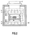
- FIG. 2 is a section of a press die performing molding by means of a press die of FIG. 1 for implementing a molding process-according to the present invention
- FIG. 3 is a partial section showing a die portion for performing molding by means of the press die of FIG. 1 in the first embodiment of the present invention
- FIG. 4 is a front elevation of a molded product of FIG. 3 ;
- FIG. 5 is a bottom view of the molded product of FIG. 4 ;
- FIG. 6 is a partial section showing the press die portion in the second embodiment of the present invention.
- FIG. 7 is a partial section of a molded product portion of the die of the present invention illustrated in FIG. 6 ;
- FIG. 8 is a front elevation of the molded product in FIG. 7 ;
- FIG. 9 is a bottom view of the molded product of FIG. 8 ;
- FIG. 10 is an exploded general section showing the press die in the ninth embodiment of the present invention.
- FIG. 11 is a plan view of an intermediate die of the press die of FIG. 10 ;
- FIG. 12 is a front elevation of the intermediate die of the press die of FIG. 11 ;
- FIG. 13 is a section of the press die for performing molding employing a press die of FIG. 10 for implementing the molding process of the ninth embodiment of the present invention
- FIG. 14 is a partial section at an initial stage of molding of the press die portion of FIG. 13 ;
- FIG. 15 is a partial section of the molded product portion of the press die of FIG. 14 ;
- FIG. 16 is a partial plan view of the molded product portion of the press die of FIG. 15 ;
- FIG. 17 is a plan view of the press die for performing molding employing a press die for implementing the molding process of the tenth embodiment of the present invention.
- FIG. 18 is a bottom view of the molded product of FIG. 17 ;
- FIG. 19 is a front elevation of the molded product of FIG. 17 ;
- FIG. 20 is a section of the press die for performing molding by means of the press die for implementing the molding process of the tenth embodiment of the present invention illustrated in FIG. 17 ;
- FIG. 21 is a partial section upon molding of the press die portion of FIG. 20 ;
- FIG. 22 is an exploded section showing the press die in the prior art
- FIG. 23 is a section of the die in the molding process employing the conventional press die of FIG. 22 ;
- FIG. 24 is a partial section of the die portion corresponding to the molding product portion of FIG. 23 ;
- FIG. 25 is a front elevation of the molded product in the prior art of FIG. 23 ;
- FIG. 26 is a bottom view of the molded product of FIG. 25 ;
- FIG. 27 is a section of the die in the assembled condition in the fourth embodiment of the present invention.
- FIG. 28 is a section of the die in the assembled condition in the fifth embodiment of the present invention.
- FIG. 29 is a section of the die in the exploded section in the sixth embodiment of the present invention.
- FIG. 30 is a section of the die in the assembled condition in the sixth embodiment of the present invention.
- FIG. 31 is an illustration showing a construction of the device in the sixth embodiment of the present invention.
- FIG. 32 is an illustration showing a force to be exerted on the molded product during press molding in the sixth embodiment of the present invention.
- FIG. 33 is an illustration showing a condition where molding is completed in FIG. 32 ;
- FIG. 34 is a section of the die in the exploded condition in the seventh embodiment of the present invention.
- FIG. 35 is a section of the die in the assembled condition in the seventh embodiment of the present invention.
- FIG. 36 is a section of the die in the exploded condition in the eighth embodiment of the present invention.
- FIG. 37 is a section of the die in the assembled condition in the eighth embodiment of the present invention.
- FIG. 38 is a diagrammatic section of a disk integrated type motor using a disk with a shaft shaped portion of the present invention.
- FIG. 39 is a diagrammatic section of a motor portion in the case where the conventional donut type disk is used.
- FIG. 40 is a perspective view of a disk drive unit assembled therein a disk integrated type motor of FIG. 38 .
- a die having a hard metal with good workability as a matrix and formed with a noble metal alloy film as protective film is optimal.
- the die is not limited to the foregoing particular die.
- noble metal alloy film it is applicable to contain at least one element selected among a group consisted of platinum (Pt), rhenium (Re), iridium (Ir), osmium (Os), palladium (Pd), rhodium (Rh) and ruthenium (Ru) as major component and also contain at least one element selected among a group consisted of tantalum (Ta), hafnium (Hf), tungsten (W), gold (Au), platinum (Pt), rhenium (Re), iridium (Ir), osmium (Os), palladium (Pd), rhodium (Rh) and ruthenium (Ru).
- the die is not specified to one employing the foregoing noble metal alloy film.
- a glass material to be employed in the present invention it is desirable to have a mechanical strength as a substrate for a magnetic disk.
- a glass material having Young's modules greater than or equal to 80 GPa is desirable.
- glass material having high chemical stability and lesser influence for the magnetic recording medium is required.
- glass material having temperature characteristics adapted to glass molding and lesser influence for the die is required.
- alumino silicate type As glass material satisfying such requirement, while not limitative, alumino silicate type, alumino borate silicate type, alumino lithium silicate type, zinc alumino silicate type glasses and so on may be applicable.
- a viscosity of glass for press molding is preferably a softening point of glass, and preferably in a range of 10 7 to 10 8 poise. If the viscosity is greater than the foregoing range, adhesion on the pressing surface of the die can be caused. Furthermore, thermal shrinkage upon cooling becomes large to cause difficulty in precise transfer of the pressing surface of the die. Thus, it becomes not possible to obtain target precision. Furthermore, breakage of the glass substrate can be caused. On the other hand, when the viscosity is smaller than the foregoing range, sufficient deformation speed cannot be obtained. When greater load is applied for obtaining sufficient deformation speed, breakage of the glass substrate can be caused.
- a press temperature is preferably as low as possible in view point of duration of the die and energy efficiency.
- a temperature close to the glass softening point (the temperature where the viscosity of glass is 10 7.6 poise) is suitable.
- the preferred press molding temperature is lower than or equal to 700° C., more preferably lower than or equal to 650° C., and further preferably lower than or equal to 600° C.
- the pressure in a range of 10 kgf/cm 2 to 600 kgf/cm 2 is preferred.
- the pressure is to be variable depending upon viscosity of the glass.
- the preferred pressure is to be less than or equal to 100 kgf/cm 2 .
- the suitable pressure is to be lower than or equal to 600 kgf/cm 2 . If the pressure is too high, breakage of glass can be caused. In significant case, deformation of the die can be caused.
- a pressure close to a critical pressure not causing breakage of the glass may be used. Such critical pressure may be derived experimentally.
- the press die for press molding of the glass substrate of the disk member having the shaft shaped portion at the center portion includes an upper die, a lower die, an intermediate die having a shaft forming hole portion for forming the shaft shaped portion, and a height restricting plate serving as a height restricting member for restricting height.
- a gas, such as air, enclosed in the shaft forming hole portion by glass material placed on the through hole of the intermediate die may be discharged through a gap between the intermediate die and the lower die according to penetration of softened glass into the shaft forming hole portion. Therefore, upon molding, no gas will resides in the shaft shaped portion to mold into accurate shape.
- the press pressure for filling the glass material into the through opening for forming the shaft shaped portion is preferred to be as low as possible for facilitating discharge of gas, and desirably lower than or equal to 100 kgf/cm 2 .
- a molding process of the disk with the shaft shaped portion employs the foregoing press die.
- the glass material having a circular section in a direction perpendicular to a center axis and having a revolving body shape including a circular section greater than the shaft forming hole portion for example, spherical glass material may be used to facilitate high precision concentricity between the shaft shaped portion and the disk member in the molded product by facilitating accurately matching the center axis of the shaft forming hole portion and the center axis of the glass material.
- the molded product with high circularity can be obtained upon press molding.
- the molded disk product having the disk member and the shaft shape portion can be obtained at high precision only by press molding. Furthermore, a plurality of press molded products can be formed simultaneously through one cycle of press molding operation.
- FIG. 1 is a section showing the first embodiment of a press die for implementing a molding process of a disk with a shaft shaped portion (outer diameter of disk portion is 25.4 mm, a thickness is 0.38 mm, a diameter of the shaft portion is 4.0 mm, a length of the shaft portion is 1.5 mm),
- FIGS. 2 to 5 are explanatory illustrations showing the molding-process.
- the press die as the first embodiment for implementing the molding process of the disk with the shaft shape portion, according to the present invention, is constructed with an upper die 1 , a height restriction plate 2 serving as a height restriction member for restricting height, an intermediate die 3 provided with a shaft forming hole portion 3 a for forming the shaft shaped portion 12 of a molded product 11 at the center, and a lower die 4 .
- the upper die 1 and a lower die 4 have protective films formed of noble metal alloy on a surface of a hard metal having a diameter of 30 mm in the press portion.
- the surface of the protective film has a surface roughness Ra of 0.5 nm and flatness of 0.2 ⁇ m.
- the intermediate die is provided with the shaft forming hole portion having a diameter of 4.0 mm.
- the protective film formed of noble metal alloy is provided on the surface of hard metal of 1.5 mm thick.
- diameter and thickness of the shaft forming hole portion are determined in consideration of thermal shrinkage of the glass during molding and thus has greater design values than the targeted glass substrate with the shaft shaped portion.
- Correction of dimension by thermal shrinkage can be derived from thermal expansion coefficient of the material or other parameters. Final correction can be experimentally adjusted adapting to the molding condition.
- the upper die 1 and the lower die 4 are respective members for press molding of an upper surface (information recording 25 surface) of the disk member 13 of the molded product 11 and a lower surface (thrust surface) of the shaft shaped portion 12 , and are of convex shape with pushing portions 1 a and 4 a and flange portions 1 b and 4 b having slightly greater diameters than those of the pushing portions 1 a and 4 a .
- the pushing portions 1 a and 4 a are adapted to engage with a hollow portion defined by the height restriction plate 2 in vertical direction.
- the height restricting plate 2 is a cylindrical member for restricting height of the disk member (thickness of the disk is 0.38 mm) and is formed into an annular ring shape formed of hard metal.
- the intermediate die 3 is disposed within the hollow space of the height restriction plate 2 to clamp between the upper and lower dies 1 and 4 . By abutting the flange portions 1 b and 4 b of the upper die 1 and the lower die 4 , movement of the press dies in the height direction is restricted. Therefore, by the height restricting member 2 , the thickness of the molded product 11 is defined.
- the intermediate die 3 is mounted on the lower die 4 .
- the height restricting plate 2 for restrict height is mounted surrounding the pushing portion 4 a of the lower die 4 and the intermediate die 3 .
- slightly compressed spherical shape glass material of alumino borate silicate type glass (softening temperature 600° C.) is placed on the shaft forming hole portion 3 a at the central portion of the intermediate die 3 .
- the height restricting plate 2 is designed to also serve as a guide for the pushing portion 1 a of the upper die 1 .
- such set of the dies are mounted on a stage 6 .
- a stage 5 is lowered to abut onto the upper die 1 to apply a load of 50 kgf for clamping the dies by the stages 5 and 6 .
- temperatures of the stages 5 and 6 are elevated by heating with heaters 7 and 8 .
- the upper die 1 , the intermediate die 3 and the lower die 4 of the press die is elevated up to a temperature of 600° C. near the softening point to perform molding of the glass material 10 .
- the stages 5 and 6 are maintained in place for 5 minutes.
- a load is increased up to 5000 kg during a 3 minutes period by means of a press 9 to pressurize the die for press molding.
- the heaters 7 and 8 are turned OFF and the load is lowered to 1000 kgf.
- the stages 5 and 6 , the upper die 1 , the intermediate die 3 , the lower die 4 and the glass material 10 are cooled down to a strain point temperature of 440° C.
- the load is lowered to 50 kgf, and the molded products are removed at a temperature lower than or equal to 100° C.
- Press molding set forth above is performed within an enclosed chamber surrounded by a casing 18 or the like under inert atmosphere filled with nitrogen. Nitrogen to be filled in the molding chamber is filtered for dust control so that press molding can be performed in clean environment.
- the glass material 10 is formed into the shape set on the mold as the molded product shown in FIGS. 4 and 5 . Dent due to presence of the residual air in the shaft portion and dent even in the disk portion due to presence of the residual air will never appear to obtain the disk with the shaft shaped portion with high precision.
- the surface roughness of the press surface of the upper die is transferred precisely so that the surface roughness Ra of the information recording surf ace of the disk portion was 0.5 nm, and the circularity was 25 ⁇ m which falls within the target range of 30 ⁇ m.
- the flatness of the disk portion was 1 ⁇ m which falls within the target flatness of 2.0 ⁇ m.
- the concentricity between the disk portion and the shaft portion was 2 ⁇ m as targeted. Thus, the motor shaft falling within the target range can be obtained.
- the press die for implementing the press molding process of the disk with the shaft shaped portion is constructed with the upper die 1 , the height restricting plate 2 , the intermediate die 3 and the lower die 4 to prevent residual gas, such as air or the like, in the tip end portion of the shaft forming hole portion 3 a as a through hole of the intermediate die 3 to obtain the press molded product 11 having the shape as designed with precisely transferring the die.
- the present invention has been illustrated and discussed in terms of the shown embodiment having the height restricting plate 2 in cylindrical member. However, it should not be specified to the shape and arrangement as the hollow ring shaped member set forth above. For instance, it is possible to arrange the height restricting plate 2 between the pushing portion 1 a of the upper die 1 and the pushing portion 4 a of the lower die 4 , to arrange the intermediate die 3 on the lower die 4 to mount the height restricting plate 2 thereon, or to mount the intermediate die 3 on the lower die 4 and to provide an appropriate guide means between the upper die 1 and the lower die 4 to provide only guiding function without restricting the height for controlling the height by detecting the height between the upper die 1 and the lower die 4 by means of a distance sensor. On the other hand, even in various embodiment, construction and arrangement of the height restricting plate can be similarly modified.
- FIGS. 6 to 9 show the second embodiment in the press die for implementing the molding process of the disk with the shaft shaped portion according to the present invention.
- a glass material 14 is preliminarily finished into the spherical shape.
- the press die used in the second embodiment of the present invention has the same construction and dimension as the die used in the foregoing first embodiment. Therefore, the press die is constructed with the upper die 1 with the pushing portion 1 a and the flange portion 1 b , the cylindrical height restricting plate 2 as the restricting member for restricting the height, the intermediate die 3 having the shaft forming hole portion 3 a for forming the shaft shaped portion 16 of the molded product 15 , and the lower die 4 with the pushing portion 4 a and the flange portion 4 b . Press molding is performed by placing the spherical glass material 14 of ⁇ 7.39 on the through hole 3 a of intermediate die 3 according to the same press molding process as the first embodiment.
- the spherical glass material 14 placed on the shaft forming hole portion 3 a of the intermediate die 3 of 4.003 mm diameter can be placed the center axis thereof matching with the center axis of the shaft forming hole portion 3 a.
- the glass material is spread in circular shape about the shaft forming hole portion 3 a at the center of the intermediate die 3 for molding the disk member 17 with the shaft shaped portion 16 by the molding surface of the pushing portion 1 a of the upper die 1 and the upper surface of the intermediate die 3 and the shaft forming hole portion 3 a for forming the shaft shaped portion. Also, concentricity between the shaft shaped portion 16 and the disk member 17 can be certainly provided.
- the obtained disk with the shaft shaped portion is molded to the shape as set on the die similarly to the first embodiment. Dent due to presence of the residual air in the shaft portion and dent even in the disk portion due to presence of the residual air will never appear to obtain the disk with the shaft shaped portion with high precision.
- the surface roughness of the press surface of the upper die is transferred precisely so that the surface roughness Ra of the information recording surface of the disk portion was 0.5 nm, and the circularity was 25 ⁇ m which falls within the target range of 30 ⁇ m.
- the flatness of the disk portion was 1 ⁇ m which falls within the target flatness of 2.0 ⁇ m.
- the concentricity between the disk portion and the shaft portion was 1.5 ⁇ m smaller than 2 ⁇ m as targeted. Therefore, the motor shaft falling within the target value can be obtained.
- the construction and dimension of the press die is similar to the foregoing first embodiment.
- the mass weight of the spherical glass material 14 is preliminarily adjusted to be equal to the mass weight (528.25 mg) of the final shape of the disk member 17 of the molded product 15 .
- a dimension t of the intermediate die 3 in the thickness direction is adapted to the dimension of the shaft shaped portion 16 of the final shape of the disk member 17 of the molded product 15 . Furthermore, a dimension as a sum of a thickness X 1 of the pushing portion 1 a of the upper die 1 , a thickness X 2 of the pushing portion 4 a of the lower die 4 , a thickness t of the intermediate die and a thickness of the disk member 17 of the molded product 15 of the final shape, is set equal to a height X 3 of the height restricting plate.
- the diameter A of the shaft shaped portion 16 and the diameter B of the disk member 17 and respective heights h 1 and h 2 of the press molded product 15 can be make equal to the dimension of the final shape of the disk member 17 of the molded product 15 .
- the obtained disk with the shaft shaped portion was molded into the shape precisely corresponding to the die similarly to the first embodiment, and did not have the dent in the shaft shaped portion due to residual air. Also, even in the disk portion, the dent due to residual air did not appear. Then, the disk with the shaft shaped portion having target dimensions of external diameter of 25.4 mm and thickness of 0.38 mm in the disk portion and of diameter of 4.0 mm and length 1.5 mm of the shaft shaped portion can be obtained.
- the surface roughness of the press surface of the upper die is transferred precisely so that the surface roughness Ra of the information recording surface of the disk portion was 0.5 nm.
- the circularity was 25 ⁇ m falling within the targeted 30 ⁇ m.
- the flatness of the disk portion was 1 ⁇ m falling within the targeted 2 ⁇ m.
- the concentricity between the disk portion and the shaft portion was 1.5 ⁇ m smaller than the targeted 2 ⁇ m.
- the motor shaft falling within the target dimension could be obtained.
- the construction and dimension of the press die is similar to the foregoing third embodiment.
- the mass weight of the spherical glass material 14 is preliminarily adjusted to be equal to the mass weight (528.25 mg) of the final shape of the disk member 17 of the molded product 15 .
- C0.2 of chamfer treatment is provided on the side of the glass material of shaft shaped portion 16 of the intermediate die 3 .
- the obtained disk with the shaft shaped portion was molded into the shape precisely corresponding to the die similarly to the third embodiment, and did not have the dent in the shaft portion due to residual air. Also, even in the disk portion, the dent due to residual air did not appear. Then, the disk with the shaft shaped portion having target dimensions of external diameter of 25.4 mm and thickness of 0.38 mm in the disk portion and of diameter of 4.0 mm and length 1.5 mm of the shaft shaped portion can be obtained.
- the surface roughness of the press surface of the upper die is transferred precisely so that the surface roughness Ra of the information recording surface of the disk portion was 0.5 nm.
- the circularity was 25 ⁇ m falling within the targeted 30 ⁇ m.
- the flatness of the disk portion was 1 ⁇ m falling within the targeted 2 ⁇ m.
- the concentricity between the disk portion and the shaft portion was 1.5 ⁇ m smaller than the targeted 2 ⁇ m.
- Fluctuation of concentricity between the molded product was improved in the extent of 20% in comparison with the third embodiment.
- the press die used in the fifth embodiment of the present invention is substantially the same as the die used in the foregoing first embodiment.
- the press die is constructed with the upper die 1 having the pushing portion 1 a and the flange portion 1 b , the cylindrical height restricting plate 2 serving as the restricting member for restricting the height, the intermediate die 3 having the shaft forming hole portion 3 a for forming the shaft shaped portion 16 of the molded product 15 and the lower die 4 having the pushing portion 4 a and the flange portion 4 b .
- Press molding is performed by placing the glass material 14 on the shaft forming hole portion 3 a as the through hole formed in the intermediate die 3 .
- a difference between the dimension X 2 of the intermediate die 3 in the thickness direction and the dimension X 3 of the lower die 4 in the thickness direction is matched with the dimension of the shaft shaped portion 16 of the final shape of the molded product 11 . Furthermore, a dimension as a sum of the thickness X 1 of the pushing portion 1 a of the upper die 1 , the dimension X 2 of the intermediate die 3 in the thickness direction and a dimension of the disk member 17 of the molded product 11 of the final shape in the thickness direction, is set equal to a height X 4 of the restricting plate.
- the intermediate die since it is only required to match the difference between the dimension X 2 of the intermediate die 3 in the thickness direction and the dimension X 3 of the lower die 4 in the thickness direction, with the dimension of the shaft shaped portion 16 of the final shape of the molded product 11 , greater thickness can be provided for the intermediate die to improve precision in machining the die. Since the intermediate die contacts with the heater directly, thermal stability can be also improved and thus circularity of the disk portion can be improved.
- the obtained disk with the shaft shaped portion was molded into the shape precisely corresponding to the die similarly to the fourth embodiment, and did not have the dent in the shaft portion due to residual air. Also, even in the disk portion, the dent due to residual air did not appear. Then, the disk with the shaft shaped portion having target dimensions of external diameter of 25.4 mm and thickness of 0.38 mm in the disk portion and of diameter of 4.0 mm and length 1.5 mm of the shaft shaped portion can be obtained.
- the surface roughness of the press surface of the upper die is transferred precisely so that the surface roughness Ra of the information recording surface of the disk portion was 0.5 nm.
- the circularity was 20 ⁇ m which is improved from the fourth embodiment and falling within the targeted 30 ⁇ m.
- the flatness of the disk portion was 1 ⁇ m falling within the targeted 2 ⁇ m.
- the concentricity between the disk portion and the shaft portion was 1.5 ⁇ m smaller than the targeted 2 ⁇ m.
- the motor shaft falling within the target dimension could be obtained.
- Fluctuation of concentricity between the molded product was equivalent to that of the fourth embodiment.
- FIGS. 29 and 30 show construction of the die of the sixth embodiment of the present invention, and FIGS. 31 to 33 are explanatory illustrations.
- the reference numeral 1 denotes the upper die for press molding the upper surface of the disk, and the molding surface is flat.
- the reference numeral 3 denotes the intermediate die for press molding the lower surface of the disk portion and the shape of the shaft portion.
- the intermediate die 3 is provided the recess treatment equal to the lower surface of the disk portion at the center thereof.
- the surface of the recess portion is flat.
- the shaft forming hole portion is processed for forming the shaft portion of the disk coaxially with the recess.
- the reference numeral 4 denotes the lower die for forming the lower surface of the shaft shaped portion.
- the molding surface of the lower die 4 is flat.
- the reference numeral 2 denotes a guide member for restricting the height of the disk.
- the guide member 2 is a hollow ring shape and clamps the intermediate die 3 .
- the flange 25 portions of the upper die 1 and the lower die 4 abut on the guide member 2 for restricting dimension in the height direction.
- h 2 h 1 + h 4 +H
- h 3 of the intermediate die 3 is expressed by: h 3 ⁇ H, H ⁇ h 3 t/ 2
- H is a total thickness of the disk with the shaft shaped portion and t is a thickness of the disk portion of the disk with the shaft shaped portion.
- the molded product 11 shown in FIG. 30 is molded by surface tension of the glass material.
- the press molding process will be explained with reference to FIG. 31 .
- the intermediate die 3 is mounted on the lower die 4
- the guide member 2 is mounted on the lower die 4 surrounding the intermediate die 3 .
- the spherical glass material 10 of mass weight (528.25 mg) equal to the mass weight of the molded product is placed on the shaft forming hole portion of the intermediate die 3 .
- the upper die 1 is placed on the glass material 10 .
- the guide member 2 also serves as guide of the upper die 1 .
- the press die is placed on the stage 6 .
- the stage 5 is lowered until it abuts against the upper die 1 to apply a load of 50 kgf to clamp the press die with the stages 5 and 6 .
- the temperature of the stages are elevated up to 600° C.
- the heaters 7 and 8 for heating respective dies and glass material 10 up to 600° C. close to glass softening point.
- the load is increased up to 5000 kgf by the press 9 over 3 minutes to apply pressure to the press die for press molding.
- a reactive force F 1 ′ acts. Further spreading of the glass material in the direction where glass contacts with the side surface of the recess portion, is blocked. Then, the glass spreads in the direction where the glass does not yet contact with the inner side surface portion of the intermediate die 3 . Finally, the glass spreads over the entire recess portion of the intermediate die 3 as shown in FIG. 33 to determine the shape of the molded product 11 .
- the obtained disk with the shaft shaped portion was molded into the shape precisely corresponding to the die similarly to the fourth embodiment, and did not have the dent in the shaft portion due to residual air. Also, even in the disk portion, the dent due to residual air did not appear. Then, the disk with the shaft shaped portion having target dimensions of external diameter of 25.4 mm and thickness of 0.38 mm in the disk portion and of diameter of 4.0 mm and length 1.5 mm of the shaft shaped portion can be obtained.
- the surface roughness of the press surface of the upper die is transferred precisely so that the surface roughness Ra of the information recording surface of the disk portion was 0.5 nm.
- the circularity was 10 ⁇ m which is improved from the fifth embodiment and falling within the targeted 30 ⁇ m.
- the flatness of the disk portion was 1 ⁇ m falling within the targeted 2 ⁇ m.
- the concentricity between the disk portion and the shaft portion was 1 ⁇ m smaller than the targeted 2 ⁇ m.
- the motor shaft falling within the target dimension could be obtained.
- the outer periphery of the molded product 11 is restricted by the recess portion of the intermediate die to permit further improvement of circularity.
- the shaft portion and the shaft shaped portion of the intermediate die because of restriction by the shaft portion and the shaft shaped portion of the intermediate die, concentricity between the disk portion and the shaft portion is also improved.
- FIGS. 34 and 35 show the seventh embodiment of the present invention.
- the construction of the press die for performing press molding is similar to the sixth embodiment, and the molding process is also similar to the sixth embodiment.
- Dimensions of the heights of the guide member 2 and the intermediate die 12 are as follows:
- the height h 2 of the guide member 2 is expressed as follow: h 2 ⁇ h 1 + h 4 + H
- H is a total thickness of the disk with the shaft shaped portion and t is a thickness of the disk portion of the disk with the shaft shaped portion.
- the guide member 2 performs only guiding of the upper die 1 , the intermediate die 3 and the lower die 4 upon press molding and does not contact with the flange portion of the upper die 1 . Then, the upper die 1 abuts with the intermediate die 5 to determine the dimension of the molding product 11 in height direction.
- the outer periphery of the molding product 11 is restricted by the recess portion of the intermediate die 3
- the shaft portion is also restricted by the shaft shaped portion of the intermediate die. Therefore, circularity of the disk portion and concentricity between the disk portion and the shaft portion can certainly be achieved. Also, with the dimension of the intermediate die 3 in the height direction, dimension of the molded product in the height direction can be determined.
- the obtained disk with the shaft shaped portion was molded into the shape precisely corresponding to the die similarly to the fourth embodiment, and did not have the dent in the shaft portion due to residual air. Also, even in the disk portion, the dent due to residual air did not appear. Then, the disk with the shaft shaped portion having target dimensions of external diameter of 25.4 mm and thickness of 0.38 mm in the disk portion and of diameter of 4.0 mm and length 1.50 mm of the shaft shaped portion can be obtained.
- the surface roughness of the press surface of the upper die is transferred precisely so that the surface roughness Ra of the information recording surface of the disk portion was 0.5 nm.
- the circularity was 10 ⁇ m which is improved from the fifth embodiment and falling within the targeted 30 ⁇ m.
- the flatness of the disk portion was 1 ⁇ m falling within the targeted 2 ⁇ m.
- the concentricity between the disk portion and the shaft portion was 1 ⁇ m smaller than the targeted 2 ⁇ m.
- the motor shaft falling within the target dimension could be obtained.
- FIGS. 36 and 37 show the eighth embodiment of the present invention.
- construction of the press die for performing press molding is substantially similar to the seventh embodiment and the molding process is also similar to the seventh embodiment.
- the intermediate die is divided into an outer frame and a bottom frame. A diameter of the bottom frame is determined to be equal to a diameter ⁇ a of the disk.
- the press molding is implemented in similar condition as the sixth embodiment.
- the obtained disk with the shaft shaped portion was molded into the shape precisely corresponding to the die similarly to the fourth embodiment, and did not have the dent in the shaft portion due to residual air. Also, even in the disk portion, the dent due to residual air did not appear. Then, the disk with the shaft shaped portion having target dimensions of external diameter of 25.4 mm and thickness of 0.38 mm in the disk portion and of diameter of 4.0 mm and length 1.5 mm of the shaft shaped portion can be obtained.
- the surface roughness of the press surface of the upper die is transferred precisely so that the surface roughness Ra of the information recording surface of the disk portion was 0.5 nm.
- the circularity was 10 ⁇ m which is improved from the fifth embodiment and falling within the targeted 30 ⁇ m.
- the flatness of the disk portion was 1 ⁇ m falling within the targeted 2 ⁇ m.
- the concentricity between the disk portion and the shaft portion was 1 ⁇ m smaller than the targeted 2 ⁇ m.
- the motor shaft falling within the target dimension could be obtained.
- FIG. 10 is an exploded general section showing the press die in the ninth embodiment of the present invention, and FIGS. 11 to 15 are explanatory illustrations of the molding process.
- the press die for implementing the ninth embodiment of the molding process according to the present invention is constructed with an upper die 21 having a pushing portion 21 a and a flange portion 21 b , a cylindrical height restricting plate 22 serving as height restricting member for restricting height of the die, an intermediate die 23 provided with a plurality of shaft forming hole portions 23 a for forming shaft shaped portions 32 of a molded product 31 , and a lower die 24 formed with a pushing portion 24 a and a flange portion 24 b.
- the upper die 21 and the lower die 24 have protective film consisted of noble metal alloy on the surface of hard metal having a press portion of 110 mm diameter.
- the surfaces of the upper die 21 and the lower die 24 have surface roughness Ra of 0.5 nm and flatness of 0.5 ⁇ m.
- the upper die 21 and the lower die 24 are designed for forming an upper surface of a disk member 33 and a lower surface of the shaft shaped portion 32 of the molded product 31 .
- Upper die 21 and lower die 24 are convex shapes respectively including the pushing portions 21 a and 24 a with flat molding surfaces and flange portions 21 b and 24 b having slightly greater dimension than the pushing portions 21 a and 24 a .
- the height restricting plate 22 (dimension: 26.880 mm) is a cylindrical member for restricting height, namely the thickness of the disk member 33 of the molded product 31 .
- the height restricting plate 22 is a hollow ring shape and clamps the intermediate die 23 .
- the height restricting plate 22 By abutting the upper and lower end of the height restricting plate 22 on the flange portions 21 b and 24 b of the upper die 21 and the lower die 24 , movement of the press dies in the height direction is restricted. Therefore, by the height restricting plate 22 , the thickness of the disk member 33 of the molded product 31 is defined.
- the intermediate die 23 is constructed with one die plate formed with a plurality of shaft forming hole portions 23 a (diameter: 4.0 mm) formed as through holes in a manner not interfering with each other.
- one shaft forming hole portion 23 a is provided at the center of the intermediate die 23 .
- six shaft forming hole portions 23 a are arranged in regular hexagonal shape (interval: 35.4 mm).
- number and arrangement the shaft forming hole portions are not limited to these 7 shaft forming hole portions 23 a in total arranged at regular hexagonal shape. Therefore, number of arrangement of the shaft forming hole portions may be selected arbitrary.
- the intermediate die 23 is mounted on the lower die 24 and the height restricting plate 22 for restricting height surrounding the lower die 24 and the intermediate die 23 .
- spherical glass materials 30 each having mass weight preliminarily adjusted to be equal to the mass weight (528.25 mg) of the final shape of the disk member 17 of the molded product, are placed on a plurality of shaft forming hole portions arranged in the intermediate die 23 .
- the upper die 21 is disposed thereon. Accordingly, at this time, the height restricting plate 22 also serves as guide for the upper die 21 .
- the set of press die is placed on a stage 26 , and a stage 25 is lowered until it abuts to the upper die 21 . Then, a load of 150 kgf is applied to clamp the press die by these stages 25 and 26 .
- temperatures of the stages 25 and 26 are elevated by heaters 27 and 28 to heat the upper die 21 , the intermediate die 23 , the lower die 24 of the press die up to 600° C. near softening point for forming the glass material 30 .
- the press die is maintained in thus clamped condition for 8 minutes.
- the load is increased to 30000 kgf over 3 minutes by the press 9 to pressurize the press die to performing press molding.
- the heaters 27 and 28 are turned OFF, and the load is lowered down to 7000 kgf.
- the stages 25 and 26 , the upper die 21 , the intermediate die 23 , the lower die 24 and the glass material 30 are cooled down.
- the load is further lowered down to 350 kgf.
- the molded products are removed at a temperature lower than or equal to 100° C.
- the glass material 30 can be molded into shape as set on the press die as the molding product 31 shown in FIGS. 15 and 16 and did not have the dent in the shaft portion due to residual air. Also, even in the disk portion, the dent due to residual air did not appear.
- the surface roughness of the press surface of the upper die is transferred precisely so that the surface roughness Ra of the information recording surface of the disk portion was 0.5 nm.
- the circularity was 25 ⁇ m falling within the targeted 30 ⁇ m.
- the flatness of the disk portion was 1.5 ⁇ m falling within the targeted 2 ⁇ m.
- the concentricity between the disk portion and the shaft portion was 1 ⁇ m smaller than the targeted 2 ⁇ m. Thus, the motor shaft falling within the target dimension could be obtained.
- the press die for implementing the molding process of the disk with the shaft shaped portion according to the present invention is constructed with the upper die 21 , the intermediate die 23 and the lower die 24 , residing of gas, such as air, in the tip end portion of the shaft forming hole portions 23 of the intermediate die 23 can be prevented.
- a plurality of molded products 31 can be formed through one molding process with shaping the glass material 30 into the shaft precisely corresponding to the press die.
- the tip end portion of the shaft shaped portion 32 of the molded product 31 can be formed satisfactorily to product a large amount of disks.
- FIGS. 16 to 21 show the tenth embodiment of the press die for implementing the molding process of the disk with the shaft shaped portion according to the present invention.
- a spherical material 40 is preliminarily finished into substantially spherical shape similarly to the former embodiment, as shown in FIG. 20 .
- the press die to be used in the tenth embodiment of the present invention is substantially the same as the basic construction as the die to be used in the former ninth embodiment.
- the intermediate die is formed with a plurality of individual die plate so that a plurality of molded products are molded independently by respective intermediate dies.
- the press die is constructed with an upper die 35 having the pushing portion 35 a and the flange portion 35 b , a cylindrical height restricting plate 36 as restricting member for restricting height, an intermediate die 37 (diameter: 30.0 mm) having shaft forming hole portion 37 a (diameter: 4.0 mm) at the center, a lower die 38 on which a plurality of intermediate dies 37 are arranged in a manner not interfering with each other.
- Respective glass materials 40 is placed on the shaft forming hole portion 37 a of respective intermediate dies.
- the intermediate die 37 is formed with a plurality of mutually independent die plates. Each die plates of the intermediate die 37 are separated corresponding to respective molded products 41 . This is the different point from the former embodiment.
- the intermediate die 37 is formed with four die plates.
- number of die plates for forming the intermediate die is not limited to any specific number but can be chosen as any arbitrary number depending upon capacity of the press die, size of the disk member 37 .
- these plurality of intermediate die plates of the intermediate die 37 are arranged in spaced apart so as not to cause interference with each other.
- Molding operation was performed in the shown embodiment under similar condition as the foregoing ninth embodiment.
- respective glass materials are to be spread in circular form about the shaft forming hole portion 37 a at the center of the respective intermediate die 37 and to be molded into a shaft shaped portion 42 and a disk portion 43 of the molded product 41 by a molding surface of the pushing portion 35 a of the upper die 35 , the upper surfaces and the shaft forming hole portion 37 a of the intermediate die 37 .
- the a plurality of the disk members 33 and the shaft member 32 with high precision concentricity can be molded as the molded products 41 corresponding to the respective intermediate die 37 .
- concentricity between the shaft shaped portion 42 and the disk shaped portion 43 of the molded product 41 can be certainly secured. Furthermore, a plurality of molded products 41 can be molded in one cycle of press molding operation simultaneously.
- the glass material 30 is formed into the shape as set in the press die as the molded products 31 shown in FIGS. 15 and 16 , and did not have the dent in the shaft portion due to residual air. Also, even in the disk portion, the dent due to residual air did not appear.
- the surface roughness of the press surface of the upper die is transferred precisely so that the surface roughness Ra of the information recording surface of the disk portion was 0.5 nm.
- the circularity was 25 ⁇ m falling within the targeted 30 ⁇ m.
- the flatness of the disk portion was 1.0 ⁇ m falling within the targeted 2 ⁇ m.
- the concentricity between the disk portion and the shaft portion was 1.0 ⁇ m smaller than the targeted 2 ⁇ m.
- the motor shaft falling within the target dimension could be obtained.
- the optimal concentricity between the shaft shaped portion 42 and the disk member 43 can be certainly attained.
Landscapes
- Engineering & Computer Science (AREA)
- Chemical & Material Sciences (AREA)
- Manufacturing & Machinery (AREA)
- Materials Engineering (AREA)
- Organic Chemistry (AREA)
- Manufacturing Of Magnetic Record Carriers (AREA)
Abstract
Description
h3=H
Claims (9)
Priority Applications (1)
| Application Number | Priority Date | Filing Date | Title |
|---|---|---|---|
| US11/300,344 US7428828B2 (en) | 2001-05-09 | 2005-12-15 | Press die of disk with shaft shaped portion |
Applications Claiming Priority (6)
| Application Number | Priority Date | Filing Date | Title |
|---|---|---|---|
| JP2001138879 | 2001-05-09 | ||
| JP2001-138879 | 2001-05-09 | ||
| JP2001-187152 | 2001-06-20 | ||
| JP2001187152 | 2001-06-20 | ||
| US10/141,344 US6997019B2 (en) | 2001-05-09 | 2002-05-09 | Molding process of disk with shaft shaped portion |
| US11/300,344 US7428828B2 (en) | 2001-05-09 | 2005-12-15 | Press die of disk with shaft shaped portion |
Related Parent Applications (1)
| Application Number | Title | Priority Date | Filing Date |
|---|---|---|---|
| US10/141,344 Division US6997019B2 (en) | 2001-05-09 | 2002-05-09 | Molding process of disk with shaft shaped portion |
Publications (2)
| Publication Number | Publication Date |
|---|---|
| US20060090517A1 US20060090517A1 (en) | 2006-05-04 |
| US7428828B2 true US7428828B2 (en) | 2008-09-30 |
Family
ID=26614826
Family Applications (2)
| Application Number | Title | Priority Date | Filing Date |
|---|---|---|---|
| US10/141,344 Expired - Fee Related US6997019B2 (en) | 2001-05-09 | 2002-05-09 | Molding process of disk with shaft shaped portion |
| US11/300,344 Expired - Fee Related US7428828B2 (en) | 2001-05-09 | 2005-12-15 | Press die of disk with shaft shaped portion |
Family Applications Before (1)
| Application Number | Title | Priority Date | Filing Date |
|---|---|---|---|
| US10/141,344 Expired - Fee Related US6997019B2 (en) | 2001-05-09 | 2002-05-09 | Molding process of disk with shaft shaped portion |
Country Status (3)
| Country | Link |
|---|---|
| US (2) | US6997019B2 (en) |
| MY (1) | MY129886A (en) |
| SG (1) | SG108848A1 (en) |
Families Citing this family (10)
| Publication number | Priority date | Publication date | Assignee | Title |
|---|---|---|---|---|
| JP4127974B2 (en) | 2001-01-29 | 2008-07-30 | Hoya株式会社 | Substrate blank, substrate, and information recording medium manufacturing method |
| MY129886A (en) * | 2001-05-09 | 2007-05-31 | Matsushita Electric Industrial Co Ltd | Molding process of disk with shaft shaped portion |
| JP4695313B2 (en) * | 2001-09-27 | 2011-06-08 | 富士フイルム株式会社 | Mold for optical element with lens barrel |
| US20030232219A1 (en) * | 2002-06-13 | 2003-12-18 | Hiroshi Nishizawa | Magnetic disk, magnetic disk manufacturing method and magnetic disk apparatus |
| JP2006079800A (en) * | 2004-08-11 | 2006-03-23 | Showa Denko Kk | Silicon substrate for magnetic recording medium, manufacturing method thereof, and magnetic recording medium |
| JP2006114198A (en) * | 2004-09-17 | 2006-04-27 | Showa Denko Kk | Silicon substrate for magnetic recording medium and magnetic recording medium |
| JP5033768B2 (en) * | 2008-10-31 | 2012-09-26 | 株式会社オハラ | Method for manufacturing thin glass sheet and disk-shaped magnetic recording medium |
| JP5431574B2 (en) * | 2010-03-31 | 2014-03-05 | Hoya株式会社 | Method for manufacturing glass blank and glass substrate for magnetic disk |
| US8931308B2 (en) | 2011-02-10 | 2015-01-13 | Hoya Corporation | Method of producing glass blank for substrate of information recording medium, substrate for information recording medium, and information recording medium; and manufacturing apparatus for glass blank for substrate of information recording medium |
| US9981844B2 (en) * | 2012-03-08 | 2018-05-29 | Infineon Technologies Ag | Method of manufacturing semiconductor device with glass pieces |
Citations (20)
| Publication number | Priority date | Publication date | Assignee | Title |
|---|---|---|---|---|
| JPS6195912A (en) | 1984-10-17 | 1986-05-14 | Matsushita Electric Ind Co Ltd | Molding method of microlens |
| JPS62230469A (en) | 1986-03-31 | 1987-10-09 | Sumitomo Light Metal Ind Ltd | Molten metal forging method |
| US4820787A (en) | 1986-03-18 | 1989-04-11 | Asahi Kasei Kogyo Kabushiki Kaisha | Shaped article of an oriented tetrafluoroethylene polymer |
| US4883528A (en) | 1989-03-08 | 1989-11-28 | Corning Incorporated | Apparatus for molding glass optical elements |
| JPH02137914A (en) | 1988-11-18 | 1990-05-28 | Matsushita Electric Ind Co Ltd | Method for manufacturing information storage disk original plate and information storage disk substrate |
| JPH0425825A (en) | 1990-05-21 | 1992-01-29 | Nippon Telegr & Teleph Corp <Ntt> | Optical fiber amplifier |
| JPH09263414A (en) | 1996-03-28 | 1997-10-07 | Olympus Optical Co Ltd | Method for forming fused grass and device therefor |
| US5788732A (en) | 1995-04-20 | 1998-08-04 | Canon Kabushiki Kaisha | Optical-device forming method and apparatus |
| US5987922A (en) | 1997-05-19 | 1999-11-23 | Hoya Corporation | Manufacturing method for molded glass articles |
| US6003336A (en) | 1993-07-28 | 1999-12-21 | Matsushita Electric Industrial Co. Ltd. | Method of manufacturing a die for press-molding optical elements |
| US6009728A (en) | 1993-07-28 | 2000-01-04 | Matsushita Electric Industrial Co., Ltd. | Die for press-molding optical elements |
| WO2001050464A1 (en) | 2000-01-05 | 2001-07-12 | Schott Glass Technologies, Inc. | Glass substrates for magnetic media and magnetic media based on such glass substrates |
| JP2002338274A (en) * | 2001-05-18 | 2002-11-27 | Matsushita Electric Ind Co Ltd | Mold for forming glass substrate for disk, method for manufacturing glass substrate for disk, manufacturing apparatus for glass substrate for disk, and glass substrate for disk |
| JP2003054964A (en) | 2001-08-07 | 2003-02-26 | Matsushita Electric Ind Co Ltd | Mold for molding and substrate for information recording disk |
| JP2003146672A (en) | 2001-11-07 | 2003-05-21 | Matsushita Electric Ind Co Ltd | Substrate molding equipment and medium mold for molding |
| JP2004067423A (en) * | 2002-08-05 | 2004-03-04 | Matsushita Electric Ind Co Ltd | Press forming method, press forming die, press forming apparatus, glass substrate manufacturing method, and glass substrate manufacturing apparatus |
| JP2004083355A (en) * | 2002-08-28 | 2004-03-18 | Matsushita Electric Ind Co Ltd | Press molding method / apparatus for glass molded product, manufacturing method / apparatus for glass substrate |
| JP2004091296A (en) | 2002-09-04 | 2004-03-25 | Matsushita Electric Ind Co Ltd | Press molding method, glass substrate with shaft for information recording medium, and information recording medium |
| JP2004131315A (en) | 2002-10-09 | 2004-04-30 | Matsushita Electric Ind Co Ltd | Manufacturing method of molding die, press molding method, glass substrate manufacturing method and manufacturing apparatus |
| US6997019B2 (en) | 2001-05-09 | 2006-02-14 | Fuji Electric Co., Ltd. | Molding process of disk with shaft shaped portion |
Family Cites Families (2)
| Publication number | Priority date | Publication date | Assignee | Title |
|---|---|---|---|---|
| JP2000072454A (en) * | 1998-08-19 | 2000-03-07 | Hoya Corp | Apparatus for production of disk-like glass and method therefor |
| JP2002187727A (en) * | 2000-12-18 | 2002-07-05 | Matsushita Electric Ind Co Ltd | Glass substrate manufacturing method and glass substrate molding die |
-
2002
- 2002-05-06 MY MYPI20021628A patent/MY129886A/en unknown
- 2002-05-08 SG SG200202735A patent/SG108848A1/en unknown
- 2002-05-09 US US10/141,344 patent/US6997019B2/en not_active Expired - Fee Related
-
2005
- 2005-12-15 US US11/300,344 patent/US7428828B2/en not_active Expired - Fee Related
Patent Citations (20)
| Publication number | Priority date | Publication date | Assignee | Title |
|---|---|---|---|---|
| JPS6195912A (en) | 1984-10-17 | 1986-05-14 | Matsushita Electric Ind Co Ltd | Molding method of microlens |
| US4820787A (en) | 1986-03-18 | 1989-04-11 | Asahi Kasei Kogyo Kabushiki Kaisha | Shaped article of an oriented tetrafluoroethylene polymer |
| JPS62230469A (en) | 1986-03-31 | 1987-10-09 | Sumitomo Light Metal Ind Ltd | Molten metal forging method |
| JPH02137914A (en) | 1988-11-18 | 1990-05-28 | Matsushita Electric Ind Co Ltd | Method for manufacturing information storage disk original plate and information storage disk substrate |
| US4883528A (en) | 1989-03-08 | 1989-11-28 | Corning Incorporated | Apparatus for molding glass optical elements |
| JPH0425825A (en) | 1990-05-21 | 1992-01-29 | Nippon Telegr & Teleph Corp <Ntt> | Optical fiber amplifier |
| US6009728A (en) | 1993-07-28 | 2000-01-04 | Matsushita Electric Industrial Co., Ltd. | Die for press-molding optical elements |
| US6003336A (en) | 1993-07-28 | 1999-12-21 | Matsushita Electric Industrial Co. Ltd. | Method of manufacturing a die for press-molding optical elements |
| US5788732A (en) | 1995-04-20 | 1998-08-04 | Canon Kabushiki Kaisha | Optical-device forming method and apparatus |
| JPH09263414A (en) | 1996-03-28 | 1997-10-07 | Olympus Optical Co Ltd | Method for forming fused grass and device therefor |
| US5987922A (en) | 1997-05-19 | 1999-11-23 | Hoya Corporation | Manufacturing method for molded glass articles |
| WO2001050464A1 (en) | 2000-01-05 | 2001-07-12 | Schott Glass Technologies, Inc. | Glass substrates for magnetic media and magnetic media based on such glass substrates |
| US6997019B2 (en) | 2001-05-09 | 2006-02-14 | Fuji Electric Co., Ltd. | Molding process of disk with shaft shaped portion |
| JP2002338274A (en) * | 2001-05-18 | 2002-11-27 | Matsushita Electric Ind Co Ltd | Mold for forming glass substrate for disk, method for manufacturing glass substrate for disk, manufacturing apparatus for glass substrate for disk, and glass substrate for disk |
| JP2003054964A (en) | 2001-08-07 | 2003-02-26 | Matsushita Electric Ind Co Ltd | Mold for molding and substrate for information recording disk |
| JP2003146672A (en) | 2001-11-07 | 2003-05-21 | Matsushita Electric Ind Co Ltd | Substrate molding equipment and medium mold for molding |
| JP2004067423A (en) * | 2002-08-05 | 2004-03-04 | Matsushita Electric Ind Co Ltd | Press forming method, press forming die, press forming apparatus, glass substrate manufacturing method, and glass substrate manufacturing apparatus |
| JP2004083355A (en) * | 2002-08-28 | 2004-03-18 | Matsushita Electric Ind Co Ltd | Press molding method / apparatus for glass molded product, manufacturing method / apparatus for glass substrate |
| JP2004091296A (en) | 2002-09-04 | 2004-03-25 | Matsushita Electric Ind Co Ltd | Press molding method, glass substrate with shaft for information recording medium, and information recording medium |
| JP2004131315A (en) | 2002-10-09 | 2004-04-30 | Matsushita Electric Ind Co Ltd | Manufacturing method of molding die, press molding method, glass substrate manufacturing method and manufacturing apparatus |
Non-Patent Citations (5)
| Title |
|---|
| Derwent Abstract Accession No. 2000-266374/23, JP 2000072545 A (Hoya Corp) Mar. 7, 2000. |
| Derwent Abstract Accession No. 2004-272418/26, JP 2003054964 A (Fuji Electric Co Ltd et al) Feb. 26, 2003. |
| Japanese Office Action dated Nov. 30, 2007 issued in counterpart Japanese Application No. 2002-109684 and translation. |
| Malaysian Search Report dated Jun. 15, 2006, issued in PI 20021628. |
| Patent Abstracts of Japan, JP, 2002187727 A (Matsushita Electrict Co Ltd et al) Jul. 5, 2002. |
Also Published As
| Publication number | Publication date |
|---|---|
| SG108848A1 (en) | 2005-02-28 |
| US20020184921A1 (en) | 2002-12-12 |
| US20060090517A1 (en) | 2006-05-04 |
| MY129886A (en) | 2007-05-31 |
| US6997019B2 (en) | 2006-02-14 |
Similar Documents
| Publication | Publication Date | Title |
|---|---|---|
| US6539750B1 (en) | Glass substrate forming mold and production method for glass substrate | |
| US7428828B2 (en) | Press die of disk with shaft shaped portion | |
| AU727634B2 (en) | Compact disc tack curing assembly line | |
| JPWO2000066504A1 (en) | Mold for molding glass substrate, glass material for molding glass substrate, manufacturing method of glass substrate, and glass substrate for magnetic disk | |
| US20080104996A1 (en) | Molding die, intermediate member, and method of manufacturing of substrate | |
| JP4102585B2 (en) | Mold for press and method for forming disk for magnetic recording medium with shaft-shaped portion | |
| JP2003201147A (en) | Method for precision drilling of glass, method for manufacturing ferrule for optical fiber connector, and method for manufacturing magnetic disk glass substrate | |
| JP2002187727A (en) | Glass substrate manufacturing method and glass substrate molding die | |
| JP2000001322A (en) | Optical element molding apparatus and optical element manufacturing method | |
| JP4524515B2 (en) | Method for producing press-molding mold for glass substrate for magnetic disk and method for producing glass substrate for magnetic disk | |
| JP3144752B2 (en) | Polishing method of diamond film | |
| JP3674910B2 (en) | Method and apparatus for producing glass molded body | |
| US20100192635A1 (en) | Molding die and manufacturing method of optical element | |
| JP4131016B2 (en) | Optical element molding apparatus and optical element manufacturing method | |
| JPH0451495B2 (en) | ||
| CN108779013B (en) | Glass blank, manufacturing method of glass blank, and manufacturing method of glass substrate for magnetic disks | |
| JP2000015546A (en) | Manufacture of glass substrate | |
| JPH11228150A (en) | Manufacture of glass substrate | |
| JP2000319026A (en) | Glass substrate molding die, glass substrate manufacturing apparatus, glass substrate manufacturing method, and magnetic disk glass substrate | |
| JPH04170331A (en) | Mold for molding optical element and production thereof and production of optical glass element | |
| JPH10255339A (en) | Method and apparatus for manufacturing optical bonded disc | |
| JP2001162626A (en) | Manufacturing method for plastic molded article and mold made of glass for molding plastic material | |
| JP2003306336A (en) | Optical element molding die | |
| JP3888159B2 (en) | Magnetic disk and manufacturing method thereof | |
| JP2002187726A (en) | Glass substrate manufacturing method and glass substrate molding die |
Legal Events
| Date | Code | Title | Description |
|---|---|---|---|
| AS | Assignment |
Owner name: FUJI ELECTRIC HOLDINGS CO., LTD., JAPAN Free format text: CHANGE OF NAME;ASSIGNOR:FUJI ELECTRIC CO., LTD.;REEL/FRAME:018244/0602 Effective date: 20031201 |
|
| AS | Assignment |
Owner name: FUJI ELECTRIC DEVICE TECHNOLOGY CO., LTD., JAPAN Free format text: ASSIGNMENT OF ASSIGNORS INTEREST;ASSIGNOR:FUJI ELECTRIC HOLDINGS CO., LTD.;REEL/FRAME:018471/0419 Effective date: 20060831 |
|
| FEPP | Fee payment procedure |
Free format text: PAYOR NUMBER ASSIGNED (ORIGINAL EVENT CODE: ASPN); ENTITY STATUS OF PATENT OWNER: LARGE ENTITY |
|
| CC | Certificate of correction | ||
| AS | Assignment |
Owner name: FUJI ELECTRIC COL, LTD., JAPAN Free format text: CHANGE OF NAME;ASSIGNOR:FUJI ELECTRIC DEVICE TECHNOLOGY CO., LTD.;REEL/FRAME:027249/0159 Effective date: 20110720 Owner name: FUJI ELECTRIC CO., LTD., JAPAN Free format text: CHANGE OF NAME;ASSIGNOR:FUJI ELECTRIC DEVICE TECHNOLOGY CO., LTD.;REEL/FRAME:027249/0159 Effective date: 20110720 Owner name: FUJI ELECTRIC CO., LTD., JAPAN Free format text: MERGER;ASSIGNOR:FUJI ELECTRIC DEVICE TECHNOLOGY CO., LTD. (MERGER);REEL/FRAME:027288/0820 Effective date: 20110720 |
|
| FPAY | Fee payment |
Year of fee payment: 4 |
|
| REMI | Maintenance fee reminder mailed | ||
| LAPS | Lapse for failure to pay maintenance fees | ||
| STCH | Information on status: patent discontinuation |
Free format text: PATENT EXPIRED DUE TO NONPAYMENT OF MAINTENANCE FEES UNDER 37 CFR 1.362 |
|
| STCH | Information on status: patent discontinuation |
Free format text: PATENT EXPIRED DUE TO NONPAYMENT OF MAINTENANCE FEES UNDER 37 CFR 1.362 |
|
| FP | Lapsed due to failure to pay maintenance fee |
Effective date: 20160930 |