US7273997B2 - Laser processing nozzle coupling - Google Patents
Laser processing nozzle coupling Download PDFInfo
- Publication number
- US7273997B2 US7273997B2 US10/913,284 US91328404A US7273997B2 US 7273997 B2 US7273997 B2 US 7273997B2 US 91328404 A US91328404 A US 91328404A US 7273997 B2 US7273997 B2 US 7273997B2
- Authority
- US
- United States
- Prior art keywords
- nozzle
- laser processing
- sleeve
- collar
- coupling assembly
- Prior art date
- Legal status (The legal status is an assumption and is not a legal conclusion. Google has not performed a legal analysis and makes no representation as to the accuracy of the status listed.)
- Expired - Lifetime
Links
- 238000012545 processing Methods 0.000 title claims abstract description 128
- 230000008878 coupling Effects 0.000 title claims abstract description 64
- 238000010168 coupling process Methods 0.000 title claims abstract description 64
- 238000005859 coupling reaction Methods 0.000 title claims abstract description 64
- 238000006073 displacement reaction Methods 0.000 claims 2
- 230000033001 locomotion Effects 0.000 description 30
- 238000003698 laser cutting Methods 0.000 description 7
- 230000008859 change Effects 0.000 description 5
- 238000000034 method Methods 0.000 description 5
- 238000005520 cutting process Methods 0.000 description 4
- 239000000463 material Substances 0.000 description 4
- 239000002184 metal Substances 0.000 description 4
- 230000007246 mechanism Effects 0.000 description 2
- 238000012986 modification Methods 0.000 description 2
- 230000004048 modification Effects 0.000 description 2
- 230000008569 process Effects 0.000 description 2
- 238000013461 design Methods 0.000 description 1
- 238000009826 distribution Methods 0.000 description 1
- 238000003780 insertion Methods 0.000 description 1
- 230000037431 insertion Effects 0.000 description 1
- 238000005457 optimization Methods 0.000 description 1
- 230000003252 repetitive effect Effects 0.000 description 1
- 238000007789 sealing Methods 0.000 description 1
- 238000000926 separation method Methods 0.000 description 1
- 238000012360 testing method Methods 0.000 description 1
- 238000003466 welding Methods 0.000 description 1
Images


Classifications
-
- B—PERFORMING OPERATIONS; TRANSPORTING
- B23—MACHINE TOOLS; METAL-WORKING NOT OTHERWISE PROVIDED FOR
- B23K—SOLDERING OR UNSOLDERING; WELDING; CLADDING OR PLATING BY SOLDERING OR WELDING; CUTTING BY APPLYING HEAT LOCALLY, e.g. FLAME CUTTING; WORKING BY LASER BEAM
- B23K26/00—Working by laser beam, e.g. welding, cutting or boring
- B23K26/14—Working by laser beam, e.g. welding, cutting or boring using a fluid stream, e.g. a jet of gas, in conjunction with the laser beam; Nozzles therefor
- B23K26/1462—Nozzles; Features related to nozzles
- B23K26/1482—Detachable nozzles, e.g. exchangeable or provided with breakaway lines
Definitions
- the invention relates to a laser processing nozzle coupling of a nozzle for a laser processing machine.
- the replacement of laser processing nozzles on a laser processing head of a laser processing machine is a repetitive process.
- a laser cutting head, and, therefore, also the cutting nozzle of a laser cutting system is especially useful for laser cutting of flat metal sheets.
- different nozzles are used with the same laser cutting head of the laser cutting system.
- Sheet metal of various thicknesses can be loaded for processing onto a workpiece support of the laser processing machine using an automatic loader.
- automatic changing of the cutting nozzle is generally not performed.
- a preliminary requirement for fully automated changing of the nozzle is the optimization of the connection between the cutting nozzle and the laser cutting head. It is generally known to screw laser processing nozzles into a laser processing head, however, rotational motions require generally more effort than are normally performed automatically.
- An apparatus is disclosed herein for simply and safely changing a laser processing nozzle in an automated manner.
- a linear motion of a laser processing nozzle is utilized to change the nozzle, and a sliding collar is utilized to release and close (i.e., lock) the laser processing nozzle coupling in its position in the processing head.
- an automatic closing mechanism for securing the laser processing nozzle in the laser processing head is achieved, and the linear motion required to change nozzles in the processing head can be automated and carried out by the laser processing machine.
- the linear motion can be a vertical motion in the direction of the Z-axis of the laser processing head or a horizontal motion relative to the motion of the laser processing head in the direction of the X or Y-axis of the processing head.
- a hollow sleeve in the processing head includes at least one bore for receiving the ball(s) that can be displaced in a radial direction. In the closed position of the processing nozzle coupling, the ball(s) can be secured toward the inside direction of the bore to achieve coupling actuation.
- the ball(s) can be displaced in the hollow sleeve toward the outside of the bore by the sliding collar to achieve coupling actuation.
- the direction of coupling actuation defines the direction of motion for releasing or locking the coupling and may be defined by the Z-, X-, or Y-direction.
- the laser processing nozzle and the sliding collar include a shoulder and/or inclined surfaces for clamping the ball and free spaces for releasing the laser processing nozzle coupling.
- the ball(s) can be locked to prevent inadvertent release of the coupling by loading the laser processing nozzle in the direction of an outlet opening of the laser beam by using a spring element, such as, for example, a bellows-type spring and loading the sliding collar by a pressure spring in the direction of the outlet opening.
- the bellow-type spring also provides hermetic sealing.
- a lip on the bore prevents the ball(s) from falling out of the bores of the hollow sleeve when the laser processing nozzle is removed.
- a sliding sleeve is disposed above the laser processing nozzle (as viewed in the direction of coupling actuation or direction of motion of the sliding sleeve), and the spring element can act through the sliding sleeve on the laser processing nozzle.
- the sliding sleeve maintains the ball(s) in their radial position and assumes the function of the laser processing nozzle.
- the pressure spring is thereby biased.
- the sliding collar cannot move downwardly due to the position and locking of the ball(s).
- the sliding collar can include a working surface for an auxiliary part for displacing the sliding collar.
- the laser processing nozzles can be changed with a purely mechanical actuating device, requiring no auxiliary energy, because the axis of the laser processing head can perform the required motions.
- the nozzle is displaceable within the sleeve along a longitudinal axis of the sleeve, and the collar is displaceable along a surface outside the sleeve.
- the sleeve, the nozzle, and the collar are adapted to co-operate to release the nozzle from a locked position within the sleeve when the nozzle is displaced in a first direction within the sleeve and then displaced in a second direction opposite to the first direction.
- the sleeve can include at least one bore through the sleeve, with at least one ball being held within the at least one bore and being displaceable within the bore between an inner position and an outer position.
- the ball is held in the inner position by a portion of the nozzle located within the sleeve and by a portion of the collar that is displaceable along the surface outside the sleeve.
- the sleeve can include three bores through the sleeve, with a ball being held in each of the three bores and displaceable within the bore between an inner position and an outer position.
- each ball When the nozzle is in the locked position, the each ball is held in the inner position by a portion of the nozzle located within the sleeve and by a portion of the collar that is displaceable along the surface outside the sleeve.
- the balls can be arranged around a circumference of the sleeve at substantially equal distances from each other.
- the assembly can include at least one spring configured to apply a force on the nozzle and on the collar in a direction in which a laser beam is emitted from the nozzle.
- the collar can include at least one recess into which the at least one ball is displaced when the nozzle is released from the sleeve.
- the nozzle can include an outer surface that is inclined with respect to an inner surface of the sleeve and that displaces the at least one ball within the bore when the nozzle is displaced within the sleeve.
- the collar can include a flange upon which the spring applies the force and that applies the force to a flange of the nozzle.
- the collar can be adapted to be displaced automatically.
- the collar can include a flange that can be grasped automatically to displace the nozzle in the first direction and in the second direction.
- the first direction and the second direction can be substantially parallel to the direction of a laser beam emitted from the nozzle.
- the first direction and the second direction also can be substantially perpendicular to the direction of a laser beam emitted from the nozzle.
- FIG. 1 is longitudinal sectional view through a laser processing nozzle coupling of a laser processing head with a laser processing nozzle, with the laser processing nozzle in a closed position.
- FIG. 2 is a detailed sectional view of the laser processing nozzle coupling in a first position.
- FIG. 3 is a detailed sectional view of the laser processing nozzle coupling in a second position.
- FIG. 4 is a detailed sectional view of the laser processing nozzle coupling in a third position.
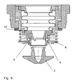
- FIG. 5 is a detailed longitudinal sectional view through the opened laser processing nozzle coupling of the laser processing head with laser processing nozzle released from the laser processing head.
- FIG. 6 is a longitudinal sectional view through a laser processing nozzle coupling of a laser processing head with a laser processing nozzle, with the laser processing nozzle in a closed position.
- FIG. 1 shows the structure of a laser processing nozzle coupling 1 with a rotationally symmetrical design.
- a reversibly connectable laser processing nozzle 2 with a nozzle opening for a laser beam LB is in a locked position when the laser processing nozzle coupling 1 is closed, which position is obtained through positive locking of corresponding functional surfaces and components explained in detail below.
- the components of the laser processing nozzle coupling 1 are connected to an associated holder 3 through which the laser processing nozzle coupling 1 is connected to further parts of the laser processing head.
- the laser processing nozzle 2 is held in a positive-locking manner through one or more balls 4 disposed on the periphery of the processing nozzle (e.g., three balls, disposed at a separation of 120° and having a spherical diameter of approximately 2 mm).
- the balls 4 are disposed in a bore of a hollow sleeve 5 such that they can move in a radial direction.
- a sliding collar 6 delimits the radial motion of the balls 4 to the outside, since a section 7 of the sliding collar 6 abuts the balls 4 .
- the sliding collar 6 is disposed to be displaceable between a first stop formed by a snap ring 6 a (disposed in a groove) and a second stop 6 b .
- the sliding collar 6 may be regarded as a substantially actuating element of the laser processing nozzle coupling 1 , which must be grasped or actuated for an automated nozzle change.
- the laser processing nozzle 2 delimits the radial motion of the balls 4 to the inside direction.
- a sliding sleeve 9 is pressed downwardly through a metal bellows spring 8 .
- the bellows spring 8 forces the sliding sleeve 9 downwardly when a laser processing nozzle 2 is not inserted in the processing nozzle coupling 1 .
- the spring force prevents the laser processing nozzle 2 from moving upwardly out of its defined position due to slight perturbations.
- the balls 4 are forced against the sliding collar 6 through a circumferential chamfer 10 on the laser processing nozzle 2 .
- the position of the laser processing nozzle 2 is thereby radially fixed by the hollow sleeve 5 and axially fixed by the balls 4 .
- Suitable cooperation between the sliding collar 6 and the sliding sleeve 9 necessitates no auxiliary motion to change the laser processing nozzle 2 .
- the laser processing nozzle properly snaps shut, as explained herein, particularly with reference to FIGS. 2-4 .
- FIGS. 2-4 exemplarily shows the release of the laser processing nozzle coupling 1 .
- An opposite closing sequence can be easily imagined on the basis of this sequence.
- the balls 4 To release the laser processing nozzle coupling 1 , the balls 4 must be pushed radially to the outside. This can be accomplished by pushing the sliding collar 6 upwardly in the direction of coupling actuation 11 (i.e., in the Z-direction) against the spring force of a pressure spring 12 , as shown in FIG. 1 , whereby the balls 4 withdraw into an annular space 13 .
- the pressure spring 12 holds the sliding collar 6 in a defined position to prevent slight motions on the sliding collar 6 from opening the laser processing nozzle coupling 1 .
- the sliding collar 6 is actuated through the application of manual force or through a corresponding device or corresponding auxiliary part, such as, for example, a ring that can be disposed onto the edge 14 of the sliding collar 6 and that can be pressure-loaded, as shown in FIG. 1 .
- the laser processing nozzle 2 To release the nozzle 2 , the laser processing nozzle 2 must initially be pushed upwardly, as shown in FIG. 3 . Lips 19 and 20 on the outer edge of the bore prevents the balls 4 from falling out of the bore after removal of the laser processing nozzle 2 . Radial inward motion of the balls 4 is possible only up to the lips 19 and 20 .
- the balls 4 can withdraw into the space 17 on the inner side that becomes free when the nozzle 2 is pushed upwardly, whereby the sliding collar 6 (see also FIG. 4 ) can be pushed upwardly, as the balls 4 are then in a position that the shoulder 16 can move past the balls 4 .
- the balls 4 can subsequently withdraw in a radial direction into the annular space 13 .
- the laser processing nozzle coupling 1 can be released only through the combination of motions, because the balls 4 can be displaced radially inwardly and outwardly, respectively.
- the bellows spring 8 exerts a force on the laser processing nozzle 2 though the sliding sleeve 9 , which forces the laser processing nozzle 2 in a downward direction.
- the motion of the sliding sleeve 9 is delimited by a flange 18 (compare FIGS. 1 and 5 ). In this position, the sliding sleeve 9 fixes the balls in their radially outwardly pushed position, whereby the sliding collar 6 is locked by the balls 4 .
- the pressure spring 12 remains biased, even if external application of force for actuation on the sliding collar 6 is omitted.
- an additional laser processing nozzle 2 can be affixed to the coupling 1 without external actuation through axial insertion in the following manner.
- the laser processing nozzle 2 initially exerts a force onto the sliding sleeve 9 , pushing it upwardly, and the balls 4 withdraw into the tapering on the laser processing nozzle 2 .
- the sliding collar 6 is thereby no longer axially supported and jumps into the position shown in FIG. 1 due to the spring bias.
- the laser processing nozzle 2 is affixed.
- Reception of the laser processing nozzle 2 and closure of the laser processing nozzle coupling 1 are effected analogously in a reverse order than the above-described release of the laser processing nozzle coupling 1 .
- Biasing of the laser processing nozzle coupling 1 greatly accelerates replacement by a new laser processing nozzle due to the sliding collar 6 , which is held in the upper position by the balls 4 .
- the pressure spring 12 participates in biasing the coupling 1 , as does the bellows spring 8 .
- the sliding sleeve 9 holds the balls 4 in the radial position and assumes the function of the laser processing nozzle 2 , and the pressure spring 12 is thereby biased.
- the sliding collar 6 cannot move downwardly due to the position and locking of the balls 4 . Therefore, the coupling 1 can snap shut automatically without external influence when the next laser processing nozzle 2 is received.
- a laser processing nozzle 2 If a laser processing nozzle 2 is inserted from below, it initially forces the sliding sleeve 9 upwardly against the spring force.
- the sliding collar 6 has no function in this process.
- the laser processing nozzle 2 exerts a pressure until the smallest nozzle diameter is at the level of the balls 4 , thereby permitting motion of the balls 4 in the direction of the beam axis, i.e., towards the center axis of the nozzle 2 .
- the balls 4 move in this direction, they permit a downward movement of the sliding collar 6 that was not possible up to now due to its shoulder 16 .
- This downward motion is supported by the spring force of the pressure spring 12 .
- the pressure spring 12 forces the sliding collar 6 again onto the stop thereby fixing the laser processing nozzle 2 . Replacement of the laser processing nozzle 2 is possible without external assistance to move components.
- references numeral 25 shows the direction of coupling actuation
- the coupling mechanism for releasing and closing is unchanged in principle, however, the sliding collar 26 and the laser processing nozzle 22 are displaced transversely to the laser beam, rather than vertically.
- the laser processing nozzle 22 is laterally coupled by a nozzle section 23 . Guidance in a groove 24 permits lateral motion.
Landscapes
- Physics & Mathematics (AREA)
- Optics & Photonics (AREA)
- Engineering & Computer Science (AREA)
- Plasma & Fusion (AREA)
- Mechanical Engineering (AREA)
- Laser Beam Processing (AREA)
Applications Claiming Priority (2)
| Application Number | Priority Date | Filing Date | Title |
|---|---|---|---|
| EP03018178A EP1506833B1 (de) | 2003-08-09 | 2003-08-09 | Laserbearbeitungsdüsenkupplung |
| EP03018178.8-2302 | 2003-08-09 |
Publications (2)
| Publication Number | Publication Date |
|---|---|
| US20050061790A1 US20050061790A1 (en) | 2005-03-24 |
| US7273997B2 true US7273997B2 (en) | 2007-09-25 |
Family
ID=33560771
Family Applications (1)
| Application Number | Title | Priority Date | Filing Date |
|---|---|---|---|
| US10/913,284 Expired - Lifetime US7273997B2 (en) | 2003-08-09 | 2004-08-09 | Laser processing nozzle coupling |
Country Status (5)
| Country | Link |
|---|---|
| US (1) | US7273997B2 (ja) |
| EP (1) | EP1506833B1 (ja) |
| JP (1) | JP5095911B2 (ja) |
| AT (1) | ATE455619T1 (ja) |
| DE (1) | DE50312360D1 (ja) |
Cited By (1)
| Publication number | Priority date | Publication date | Assignee | Title |
|---|---|---|---|---|
| US11697175B2 (en) | 2017-10-05 | 2023-07-11 | Synova S.A. | Apparatus for machining a workpiece with a laser beam |
Families Citing this family (10)
| Publication number | Priority date | Publication date | Assignee | Title |
|---|---|---|---|---|
| JP4723456B2 (ja) | 2006-10-27 | 2011-07-13 | 三菱電機株式会社 | 加工ヘッドおよびノズル交換装置およびレーザ加工装置 |
| DE102007024288B3 (de) | 2007-05-23 | 2008-10-16 | Trumpf Werkzeugmaschinen Gmbh + Co. Kg | Anordnung zur Erkennung einer Laserbearbeitungsdüse beim Einsetzen der Laserbearbeitungsdüse in einen Laserbearbeitungskopf |
| FR2975318B1 (fr) * | 2011-05-16 | 2014-05-09 | Air Liquide | Buse laser a element mobile |
| EP2674238B1 (en) * | 2012-06-15 | 2017-09-27 | Agie Charmilles New Technologies SA | Laser machine comprising a tool holder with guiding and locking system |
| JP6139918B2 (ja) * | 2013-03-06 | 2017-05-31 | 株式会社アマダホールディングス | レーザ加工機 |
| DE202017103742U1 (de) | 2017-06-23 | 2017-07-18 | Trumpf Laser Gmbh | Steckeraufnahme für einen Faserstecker eines Lichtleitkabels |
| EP3470165B1 (en) * | 2017-10-13 | 2023-08-16 | Synova S.A. | Apparatus for machining a workpiece with a liquid jet guided laser beam and the assembly thereof |
| WO2020264122A1 (en) * | 2019-06-25 | 2020-12-30 | Hypertherm, Inc. | Locking mechanisms in a material processing system |
| DE102022112050A1 (de) | 2022-05-13 | 2023-11-16 | TRUMPF Werkzeugmaschinen SE + Co. KG | Düse für die Laserbearbeitung mit hohen Fokuslagen |
| CN115074727B (zh) * | 2022-06-30 | 2023-04-18 | 江西制造职业技术学院 | 一种激光熔覆气氛保护装置 |
Citations (31)
| Publication number | Priority date | Publication date | Assignee | Title |
|---|---|---|---|---|
| US3247978A (en) | 1962-12-12 | 1966-04-26 | Programmed & Remote Syst Corp | Manipulator hand |
| US3761117A (en) * | 1972-04-19 | 1973-09-25 | Crawford Fitting Co | Quick connect fitting |
| US4114853A (en) * | 1976-10-08 | 1978-09-19 | Swagelok Company | Quick connect coupling |
| GB2089918A (en) * | 1980-12-19 | 1982-06-30 | Harwood Royston Peter | Quick-connect coupling |
| US4549846A (en) | 1982-04-27 | 1985-10-29 | Fanuc Ltd | Automatic hand changing device for industrial robots |
| US4598581A (en) * | 1984-06-25 | 1986-07-08 | Fmc Corporation | Quick connect diagnostic system |
| US4733457A (en) * | 1985-02-04 | 1988-03-29 | Metalmeccanica Gori & Zucchi M.G.Z. S.P.A. | Apparatus for the automation of operative systems with mechanical hand or the like |
| US4740058A (en) * | 1986-08-29 | 1988-04-26 | Technology For Imaging, Inc. | Coupler for optical instruments |
| US4966398A (en) * | 1989-02-14 | 1990-10-30 | Buell Industries, Inc. | Fluid conduit coupling |
| EP0411535A2 (en) | 1989-08-01 | 1991-02-06 | PRIMA INDUSTRIE S.p.A. | Laser machine for cutting and welding |
| US5064991A (en) * | 1990-01-31 | 1991-11-12 | Comau S.P.A. | Device for laser welding motor-vehicle bodies |
| US5074332A (en) * | 1990-08-16 | 1991-12-24 | Production Control Units, Inc. | Hose coupling unit for refrigerant system |
| US5128508A (en) * | 1990-04-14 | 1992-07-07 | Trumpf Gmbh & Company | Nozzle for laser cutting head |
| EP0548404A1 (en) | 1990-06-28 | 1993-06-30 | Bl Autotec, Ltd | Robot arm coupling apparatus |
| USRE34426E (en) * | 1987-11-05 | 1993-11-02 | Production Control Units, Inc. | Dispensing tool assembly for charging a refrigerant into a system |
| GB2299777A (en) | 1995-04-01 | 1996-10-16 | M J Tech Ltd | Laser nozzle mounting |
| US5896889A (en) * | 1997-10-24 | 1999-04-27 | Menard; Orville R. | Quick-set hydraulic coupler |
| US5897795A (en) * | 1996-10-08 | 1999-04-27 | Hypertherm, Inc. | Integral spring consumables for plasma arc torch using blow forward contact starting system |
| US6058971A (en) * | 1998-08-31 | 2000-05-09 | Seychelle Environmental Technologies, Inc. | Quick-connect diverter valve |
| DE19944484C1 (de) | 1999-09-16 | 2001-04-19 | Precitec Gmbh | Wechselvorrichtung für einen Linsenhalter eines Anschlusskopfs zur Bearbeitung eines Werkstücks mittels eines Laserstrahls |
| US6234274B1 (en) * | 1999-04-23 | 2001-05-22 | K. J. Manufacturing, Inc. | Low profile nipple |
| US6315544B1 (en) * | 1999-10-07 | 2001-11-13 | Burger Engineering, Inc. | Adjustable length extension bars for connecting a mold ejector plate to a press ejector plate |
| DE10056330C1 (de) | 1999-09-16 | 2002-03-07 | Precitec Kg | Wechselvorrichtung für einen Linsenhalter eines Anschlußkopfs zur Bearbeitung eines Werkstücks mittels eines Laserstrahls |
| JP2002160085A (ja) * | 2000-11-14 | 2002-06-04 | Precitec Kg | レーザ加工接続ヘッドのレンズホルダ用交換装置 |
| US6398279B1 (en) | 1997-10-10 | 2002-06-04 | Kuka Schweissanlagen Gmbh | Interchangeable coupling |
| EP1215018A1 (en) | 2000-12-13 | 2002-06-19 | COM.IMP.EX. di Elio Strobietto | Device for connecting a tool on a robot arm using balls as locking members |
| US6505863B2 (en) * | 2000-07-11 | 2003-01-14 | Surpass Industry Co., Ltd. | Connector |
| US6534745B1 (en) * | 1999-09-27 | 2003-03-18 | Mathew T. J. Lowney | Nozzle particularly suited to direct metal deposition |
| US6604944B2 (en) * | 1999-11-24 | 2003-08-12 | Crystalmark Dental Systems, Inc. | Handpiece assembly for air abrasion |
| US6761361B2 (en) * | 2002-08-09 | 2004-07-13 | Credo Technology Corporation | Drill and drive apparatus with improved tool holder |
| US6951298B1 (en) * | 1999-02-12 | 2005-10-04 | Henrob Limited | Fastener delivery apparatus |
Family Cites Families (3)
| Publication number | Priority date | Publication date | Assignee | Title |
|---|---|---|---|---|
| JPH0518487A (ja) * | 1991-07-10 | 1993-01-26 | Sekisui Chem Co Ltd | 管の接続部構造 |
| JPH106062A (ja) * | 1996-06-24 | 1998-01-13 | Amada Co Ltd | Yagレーザー加工ヘッド及び同加工ヘッドに使用するレーザー加工用ノズル及び同レーザー加工用ノズルのノズルマガジン |
| JP3198095B2 (ja) * | 1998-10-21 | 2001-08-13 | ファナック株式会社 | レーザ加工装置 |
-
2003
- 2003-08-09 AT AT03018178T patent/ATE455619T1/de not_active IP Right Cessation
- 2003-08-09 EP EP03018178A patent/EP1506833B1/de not_active Expired - Lifetime
- 2003-08-09 DE DE50312360T patent/DE50312360D1/de not_active Expired - Lifetime
-
2004
- 2004-08-04 JP JP2004228558A patent/JP5095911B2/ja not_active Expired - Fee Related
- 2004-08-09 US US10/913,284 patent/US7273997B2/en not_active Expired - Lifetime
Patent Citations (31)
| Publication number | Priority date | Publication date | Assignee | Title |
|---|---|---|---|---|
| US3247978A (en) | 1962-12-12 | 1966-04-26 | Programmed & Remote Syst Corp | Manipulator hand |
| US3761117A (en) * | 1972-04-19 | 1973-09-25 | Crawford Fitting Co | Quick connect fitting |
| US4114853A (en) * | 1976-10-08 | 1978-09-19 | Swagelok Company | Quick connect coupling |
| GB2089918A (en) * | 1980-12-19 | 1982-06-30 | Harwood Royston Peter | Quick-connect coupling |
| US4549846A (en) | 1982-04-27 | 1985-10-29 | Fanuc Ltd | Automatic hand changing device for industrial robots |
| US4598581A (en) * | 1984-06-25 | 1986-07-08 | Fmc Corporation | Quick connect diagnostic system |
| US4733457A (en) * | 1985-02-04 | 1988-03-29 | Metalmeccanica Gori & Zucchi M.G.Z. S.P.A. | Apparatus for the automation of operative systems with mechanical hand or the like |
| US4740058A (en) * | 1986-08-29 | 1988-04-26 | Technology For Imaging, Inc. | Coupler for optical instruments |
| USRE34426E (en) * | 1987-11-05 | 1993-11-02 | Production Control Units, Inc. | Dispensing tool assembly for charging a refrigerant into a system |
| US4966398A (en) * | 1989-02-14 | 1990-10-30 | Buell Industries, Inc. | Fluid conduit coupling |
| EP0411535A2 (en) | 1989-08-01 | 1991-02-06 | PRIMA INDUSTRIE S.p.A. | Laser machine for cutting and welding |
| US5064991A (en) * | 1990-01-31 | 1991-11-12 | Comau S.P.A. | Device for laser welding motor-vehicle bodies |
| US5128508A (en) * | 1990-04-14 | 1992-07-07 | Trumpf Gmbh & Company | Nozzle for laser cutting head |
| EP0548404A1 (en) | 1990-06-28 | 1993-06-30 | Bl Autotec, Ltd | Robot arm coupling apparatus |
| US5074332A (en) * | 1990-08-16 | 1991-12-24 | Production Control Units, Inc. | Hose coupling unit for refrigerant system |
| GB2299777A (en) | 1995-04-01 | 1996-10-16 | M J Tech Ltd | Laser nozzle mounting |
| US5897795A (en) * | 1996-10-08 | 1999-04-27 | Hypertherm, Inc. | Integral spring consumables for plasma arc torch using blow forward contact starting system |
| US6398279B1 (en) | 1997-10-10 | 2002-06-04 | Kuka Schweissanlagen Gmbh | Interchangeable coupling |
| US5896889A (en) * | 1997-10-24 | 1999-04-27 | Menard; Orville R. | Quick-set hydraulic coupler |
| US6058971A (en) * | 1998-08-31 | 2000-05-09 | Seychelle Environmental Technologies, Inc. | Quick-connect diverter valve |
| US6951298B1 (en) * | 1999-02-12 | 2005-10-04 | Henrob Limited | Fastener delivery apparatus |
| US6234274B1 (en) * | 1999-04-23 | 2001-05-22 | K. J. Manufacturing, Inc. | Low profile nipple |
| DE19944484C1 (de) | 1999-09-16 | 2001-04-19 | Precitec Gmbh | Wechselvorrichtung für einen Linsenhalter eines Anschlusskopfs zur Bearbeitung eines Werkstücks mittels eines Laserstrahls |
| DE10056330C1 (de) | 1999-09-16 | 2002-03-07 | Precitec Kg | Wechselvorrichtung für einen Linsenhalter eines Anschlußkopfs zur Bearbeitung eines Werkstücks mittels eines Laserstrahls |
| US6534745B1 (en) * | 1999-09-27 | 2003-03-18 | Mathew T. J. Lowney | Nozzle particularly suited to direct metal deposition |
| US6315544B1 (en) * | 1999-10-07 | 2001-11-13 | Burger Engineering, Inc. | Adjustable length extension bars for connecting a mold ejector plate to a press ejector plate |
| US6604944B2 (en) * | 1999-11-24 | 2003-08-12 | Crystalmark Dental Systems, Inc. | Handpiece assembly for air abrasion |
| US6505863B2 (en) * | 2000-07-11 | 2003-01-14 | Surpass Industry Co., Ltd. | Connector |
| JP2002160085A (ja) * | 2000-11-14 | 2002-06-04 | Precitec Kg | レーザ加工接続ヘッドのレンズホルダ用交換装置 |
| EP1215018A1 (en) | 2000-12-13 | 2002-06-19 | COM.IMP.EX. di Elio Strobietto | Device for connecting a tool on a robot arm using balls as locking members |
| US6761361B2 (en) * | 2002-08-09 | 2004-07-13 | Credo Technology Corporation | Drill and drive apparatus with improved tool holder |
Cited By (1)
| Publication number | Priority date | Publication date | Assignee | Title |
|---|---|---|---|---|
| US11697175B2 (en) | 2017-10-05 | 2023-07-11 | Synova S.A. | Apparatus for machining a workpiece with a laser beam |
Also Published As
| Publication number | Publication date |
|---|---|
| DE50312360D1 (de) | 2010-03-11 |
| JP2005059099A (ja) | 2005-03-10 |
| JP5095911B2 (ja) | 2012-12-12 |
| ATE455619T1 (de) | 2010-02-15 |
| US20050061790A1 (en) | 2005-03-24 |
| EP1506833A1 (de) | 2005-02-16 |
| EP1506833B1 (de) | 2010-01-20 |
Similar Documents
| Publication | Publication Date | Title |
|---|---|---|
| US7273997B2 (en) | Laser processing nozzle coupling | |
| US10668631B2 (en) | Compensating device for a handling unit and handling unit comprising the compensating device | |
| JP5307411B2 (ja) | 締付け装置 | |
| US4171821A (en) | Quick change collet tool holder assembly | |
| KR102432788B1 (ko) | 특히 컨테이너들인 물체들을 핸들링하기 위한 로봇 그립퍼 | |
| US20120073092A1 (en) | Clamping device and method of clamping | |
| KR20100105858A (ko) | 공작물 팔레트 위치결정 고정장치 | |
| CN101204778A (zh) | 在夹盘上定位工件的工件支座及带夹盘和工件支座的夹具 | |
| KR20200035315A (ko) | 샤프트의 자동 교체를 위한 방법 및 시스템 | |
| CN102438934A (zh) | 用于为瓶加盖的加盖头和设备 | |
| US20130075984A1 (en) | Securing device for securing a chuck on a rotating spindle | |
| US6375398B1 (en) | Tool holder assembly | |
| JP5475997B2 (ja) | ホーニングツールをホーニングスピンドルに連結するための方法、ホーニングスピンドル、ホーニングツールおよびホーニング装置 | |
| US4688810A (en) | Support for a chuck | |
| US6910693B2 (en) | Draw down chuck | |
| US7104940B2 (en) | Tool changer for a machine tool | |
| US11135692B2 (en) | Tool holder or workpiece holder and set comprising machine tool and tool holder or workpiece holder | |
| US20080169618A1 (en) | Positive release collet | |
| US5957468A (en) | Collet device | |
| JP2012115953A (ja) | 工具ポット | |
| EP4052841A1 (en) | Clamp device | |
| EP3750653B1 (en) | Clamping decvice for tool holder | |
| CN113056342B (zh) | 定位装置 | |
| US20240165714A1 (en) | Gripping device for holding, centring and/or collet-clamping a micromechanical or horological component | |
| CN111621882B (zh) | 筒管杯座 |
Legal Events
| Date | Code | Title | Description |
|---|---|---|---|
| AS | Assignment |
Owner name: TRUMPF WERKZEUGMASCHINEN GMBH + CO. KG, GERMANY Free format text: ASSIGNMENT OF ASSIGNORS INTEREST;ASSIGNORS:LAMBERT, MARTIN;HERWERTH, PHILIPP;REEL/FRAME:016037/0190 Effective date: 20041104 |
|
| STCF | Information on status: patent grant |
Free format text: PATENTED CASE |
|
| FEPP | Fee payment procedure |
Free format text: PAYOR NUMBER ASSIGNED (ORIGINAL EVENT CODE: ASPN); ENTITY STATUS OF PATENT OWNER: LARGE ENTITY |
|
| FPAY | Fee payment |
Year of fee payment: 4 |
|
| FPAY | Fee payment |
Year of fee payment: 8 |
|
| FEPP | Fee payment procedure |
Free format text: PAYER NUMBER DE-ASSIGNED (ORIGINAL EVENT CODE: RMPN); ENTITY STATUS OF PATENT OWNER: LARGE ENTITY Free format text: PAYOR NUMBER ASSIGNED (ORIGINAL EVENT CODE: ASPN); ENTITY STATUS OF PATENT OWNER: LARGE ENTITY |
|
| MAFP | Maintenance fee payment |
Free format text: PAYMENT OF MAINTENANCE FEE, 12TH YEAR, LARGE ENTITY (ORIGINAL EVENT CODE: M1553); ENTITY STATUS OF PATENT OWNER: LARGE ENTITY Year of fee payment: 12 |