US7240877B2 - Multi-engined aircraft with lowering shaft - Google Patents
Multi-engined aircraft with lowering shaft Download PDFInfo
- Publication number
- US7240877B2 US7240877B2 US11/179,611 US17961105A US7240877B2 US 7240877 B2 US7240877 B2 US 7240877B2 US 17961105 A US17961105 A US 17961105A US 7240877 B2 US7240877 B2 US 7240877B2
- Authority
- US
- United States
- Prior art keywords
- fuselage
- engine
- tail
- aircraft
- lowering shaft
- Prior art date
- Legal status (The legal status is an assumption and is not a legal conclusion. Google has not performed a legal analysis and makes no representation as to the accuracy of the status listed.)
- Expired - Fee Related, expires
Links
- 238000000926 separation method Methods 0.000 claims description 3
- 238000006073 displacement reaction Methods 0.000 claims description 2
- 238000012423 maintenance Methods 0.000 description 5
- 238000009434 installation Methods 0.000 description 2
- 239000003381 stabilizer Substances 0.000 description 2
- 235000010627 Phaseolus vulgaris Nutrition 0.000 description 1
- 244000046052 Phaseolus vulgaris Species 0.000 description 1
- 238000007630 basic procedure Methods 0.000 description 1
- 239000012530 fluid Substances 0.000 description 1
- 238000000034 method Methods 0.000 description 1
Images


Classifications
-
- B—PERFORMING OPERATIONS; TRANSPORTING
- B64—AIRCRAFT; AVIATION; COSMONAUTICS
- B64D—EQUIPMENT FOR FITTING IN OR TO AIRCRAFT; FLIGHT SUITS; PARACHUTES; ARRANGEMENT OR MOUNTING OF POWER PLANTS OR PROPULSION TRANSMISSIONS IN AIRCRAFT
- B64D27/00—Arrangement or mounting of power plants in aircraft; Aircraft characterised by the type or position of power plants
- B64D27/02—Aircraft characterised by the type or position of power plants
- B64D27/16—Aircraft characterised by the type or position of power plants of jet type
- B64D27/20—Aircraft characterised by the type or position of power plants of jet type within, or attached to, fuselages
Definitions
- the present invention relates to a multi-engined aircraft of the type in which one of the engines is more particularly placed at the tail of the fuselage, which comprises the rear tail units, and in the vertical longitudinal plane of symmetry of the fuselage.
- the third engine is structurally and geometrically located between the horizontal tail unit with its two symmetrical stabilizers and the vertical tail unit with its vertical stabilizer disposed on the nacelle or the fairing of this third engine.
- Other aircraft integrate the tail engine at the end of the fuselage, directly in its structure.
- the purpose of the present invention is to overcome these disadvantages.
- the multi-engined aircraft of which one of the engines is positioned at the tail of the fuselage, which comprises the rear tail units, and in the vertical longitudinal plane of symmetry of said fuselage is noteworthy, according to the invention, in that said tail engine is disposed in front of said rear tail units, on the upper part of the tail of the fuselage, in that said tail engine is mounted, in a detachable manner, on a rigid supporting structure attached to that of said fuselage and in that there is formed, in the tail of said fuselage and plumb with said engine supported by said structure, a vertical lowering shaft for the passage of said engine between, on the one hand, a high position corresponding to the operational position of said engine and, on the other hand, following the separation of said engine from the supporting structure and its displacement through said lowering shaft, a low position in which said engine has come out of said fuselage and is under said tail.
- said supporting structure comprises at least one beam from which said engine is suspended by means of fixing attachments, and structural arches supporting said beam and attached to the structure of said fuselage.
- said beam of the support structure is disposed substantially horizontally in said plane of symmetry and said structural arches are parallel with each other and perpendicular to said beam which they support.
- said aligned structural arches have the shape of an inverted U passing over the top of said engine, the side members of each arch being integral with the structure of the fuselage and said beam from which said engine is suspended via the fixing attachments is attached to the outside of the rounded tops of the inverted U-shaped arches.
- said beam is preferably a double beam and comprises two identical beans fitted one against the other. Thus, if one of the beams fails, the other one withstands.
- the upper part of the tail of the fuselage, upon which said engine is placed has a flattened configuration.
- the rear tail units define a channel, for example substantially U-shaped, that is geometrically symmetrical with respect to the plane of symmetry of the fuselage, the tail engine thus being disposed in front of said U-shaped channel.
- said opening formed in the lower part of the fuselage is obturated by a hatch, articulated on the structure of said fuselage and defining, when it is lowered, an access stairway to the inside of the fuselage.
- the opening of the hatch or its withdrawal from the fuselage if it is detachable then allows the lowering (or raising) of the tail engine via said shaft.
- the engine is furthermore confined in a nacelle attached in a fixed manner to the upper part of said fuselage.
- the upper opening is surrounded by the nacelle.
- said nacelle can comprise a forward air-intake cowl for said engine, a detachable central cowl disposed around the fan of the engine, and a detachable rear cowl disposed around the turbine, said cowls being fixed to the upper part of said fuselage and surrounding its upper opening.
- a box-type structure can be fitted in said lowering shaft of said fuselage, at the place where the engine passes through the latter, for example for purposes of maintenance directly on board the aircraft or for the purpose of transporting freight and/or luggage.
- FIG. 1 is a perspective view of a multi-engined aircraft according to the invention, comprising an engine at the tail of the fuselage.
- FIG. 2 is a side view of the aircraft shown in FIG. 1 .
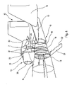
- FIG. 3 is a diagrammatic representation in perspective of the tail engine assembly on the structure of the fuselage.
- FIGS. 4 to 6 diagrammatically show the sequences of lowering the tail engine through the fuselage.
- FIG. 7 is a perspective rear view from below of the tail of the fuselage.
- the aircraft 1 comprises three engines of the turbojet type. Two of the engines, referenced 2 and 3 , are disposed under the wings 4 , 5 of the fuselage 6 respectively symmetrically with respect to the vertical longitudinal plane of symmetry P of the latter and the third engine 7 is provided in this plane of symmetry P and at the level of the tail 9 of the fuselage, which comprises the horizontal 10 and vertical 11 rear tail units.
- the reference 13 refers to the landing gear of the aircraft.
- the tail engine 7 is advantageously situated on the upper part 8 of the tail 9 and in front of the horizontal and vertical tail units which therefore define a substantially U-shaped channel 12 in this example, geometrically symmetrical with respect to the longitudinal plane P of the fuselage (the rear tail units defining the channel could also be H-shaped or V-shaped).
- the outlet of the engine 7 is at the entrance of the U-shaped channel of the tail units 10 , 11 , in the plane of symmetry, the emitted gasses are directed inside of the channel, without harming the tail units.
- the engine 7 is mounted, in a detachable manner, on a rigid supporting structure 15 connected with that of the fuselage which is defined, among other things, by structural frames 20 .
- a vertical lowering shaft 16 is then formed in the tail 9 of the fuselage, plumb with the engine 7 and in the plane of symmetry, in order to allow its passage between its high position, in which it is operational and attached to the supporting structure 15 , and a low position, in which it has been taken out of the fuselage through the shaft 16 for the purpose of maintenance or replacement.
- FIGS. 1 to 3 it can be seen that the lower opening 18 is obturated by a hatch 21 articulated on the structure of the fuselage 6 and merging with its profile and which is, in this example, detachable.
- the hatch 21 can therefore be withdrawn from the fuselage when it is desired to proceed with the lowering of said engine, as will be seen below, or simply lowered to reveal a stairway 22 , when it is desired to gain access to the inside of the fuselage.
- the hatch could be made in two parts (doors or flaps) that are symmetrical with respect to the longitudinal plane of the aircraft and without a stairway.
- the two parts are articulated laterally on the fuselage, like some landing gear hatches, and are not detachable. With regard to the upper opening 17 , this can be left as it is since it is surrounded by the bottom part of the nacelle 14 , which is attached in a fixed manner to the upper flattened part 8 of the fuselage. It could also be obturated.
- the supporting structure 15 comprises a double beam 23 supporting the engine 7 and two structural arches 24 supporting the double beam (the structure could also be of the box-sectioned or trellis type).
- the double beam 23 is positioned horizontally in the plane of symmetry P and consists of two identical and substantially straight beams 23 A, 23 B, disposed one against the other. From this double beam 23 is suspended the engine 7 by fixing attachments 25 , 26 , one of which 25 is provided at the rear end of the double beam (at the right hand end in FIG. 3 ) and supports the outer casing 7 A of the turbine 7 B of the engine and the other of which 26 is situated in the median section of the double beam and supports the external casing 7 C of the fan 7 D.
- the structural arches 24 are identical and have the shape of an inverted U, whilst being disposed in planes perpendicular to the plane of symmetry P of the fuselage.
- the double beam 23 is attached to the rounded tops of the arches 24 A by means of fixing attachments, one of which 27 is provided at the front end of the double beam (at the left hand end in FIG. 3 ) and the other of which 28 is situated in the median or central section of the latter, beside the engine attachment 26 .
- the fixing attachments 25 , 26 , 27 and 28 are duplicated in the same way as the beam is.
- the inverted U-shaped arches straddle the engine 7 and their lateral members 24 B are attached in a fixed manner to the structural frames 20 of the fuselage.
- the arches participate in the rigidifying of the structure of the fuselage and the length of the members makes it possible to bring the engine easily above the upper part 8 of the fuselage.
- the nacelle 14 surrounding the supporting structure 15 and the engine 7 principally consists of three successive parts or cowls:
- a box-type structure 29 as shown in FIG. 7 , accessible for example from the stairway 22 integrated with the hatch 21 , which is therefore lowered.
- This box-type structure 29 can receive technicians allowing them to carry out, in particular, maintenance operations inside the fuselage, for example on the circuits running along the latter, and on the tail engine, or it can contain freight or luggage.
- the aircraft 1 being brought to a suitable area, the lower hatch 21 is lowered and the detachable flaps constituting the central and rear cowls 31 and 32 , which surround the engine 7 , are raised as shown in FIG. 4 .
- said cowls could be removed if necessary.
- the outer ring 7 F and the internal cone 7 G of the nozzle are then detached from the rest of the engine as shown in FIG. 5 .
- This dismantling which is carried out without any particular problems, avoids having to provide passage openings and a shaft that are too large in the tail of the fuselage.
- the hatch 21 is furthermore removed from the fuselage 6 , totally uncovering the lowering shaft 16 . If the box-type structure 29 is present in the latter, it is of course removed from it.
- the fluid circuits and other pieces of equipment connected to the engine are disconnected and handling equipment is brought in to lower the engine.
- the latter can be in the form, shown diagrammatically by an arrow F in FIGS. 5 and 6 , of a motorized lifting machine equipped with extensible means (X jacks) at the end of which is a cradle structure capable of supporting the engine.
- the handling equipment could also be a hoist system overhanging the tail of the fuselage and allowing, by means of a simple vertical movement, the lowering (or raising) of the tail engine through the shaft.
- the double beam 23 could support the hoists making it possible to obtain total autonomy for the fitting/detachment of the engine.
- a simple open area for example, advantageously suffices.
- the engine is in the process of being lowered by means of the handling equipment and passes through the openings 17 , 18 and the shaft 16 until it emerges from the tail 9 of the fuselage 6 , as shown in FIG. 6 . From there, it can be taken into specialized workshops. It can therefore be understood, from the preceding description of the invention, that the maintenance of such a tail engine situated on the upper part of the fuselage, is made particularly easy, like that of a wing engine.
Landscapes
- Engineering & Computer Science (AREA)
- Aviation & Aerospace Engineering (AREA)
- Structures Of Non-Positive Displacement Pumps (AREA)
- Toys (AREA)
- Automatic Assembly (AREA)
- Automatic Cycles, And Cycles In General (AREA)
- Braking Arrangements (AREA)
- Valves And Accessory Devices For Braking Systems (AREA)
Applications Claiming Priority (2)
| Application Number | Priority Date | Filing Date | Title |
|---|---|---|---|
| FR0407864A FR2873095B1 (fr) | 2004-07-15 | 2004-07-15 | Avion multimoteur a puits de descente |
| FR0407864 | 2004-07-15 |
Publications (2)
| Publication Number | Publication Date |
|---|---|
| US20060011779A1 US20060011779A1 (en) | 2006-01-19 |
| US7240877B2 true US7240877B2 (en) | 2007-07-10 |
Family
ID=34942385
Family Applications (1)
| Application Number | Title | Priority Date | Filing Date |
|---|---|---|---|
| US11/179,611 Expired - Fee Related US7240877B2 (en) | 2004-07-15 | 2005-07-13 | Multi-engined aircraft with lowering shaft |
Country Status (7)
| Country | Link |
|---|---|
| US (1) | US7240877B2 (fr) |
| EP (1) | EP1616786B1 (fr) |
| AT (1) | ATE348037T1 (fr) |
| CA (1) | CA2510673C (fr) |
| DE (1) | DE602005000328T2 (fr) |
| ES (1) | ES2277321T3 (fr) |
| FR (1) | FR2873095B1 (fr) |
Cited By (6)
| Publication number | Priority date | Publication date | Assignee | Title |
|---|---|---|---|---|
| US20100108802A1 (en) * | 2008-08-04 | 2010-05-06 | Airbus Operations Sas | Sail wing aircraft which includes an engine mounted on a pylon |
| US20110226899A1 (en) * | 2007-04-25 | 2011-09-22 | Airbus France | Autonomous plane architecture for the transport and the replacement of propulsion engines |
| US20120138736A1 (en) * | 2009-03-12 | 2012-06-07 | Airbus Operations (S.A.S.) | Airplane with a tailcoat tail assembly and rear engine |
| EP3040264A1 (fr) * | 2014-12-30 | 2016-07-06 | Airbus Operations S.L. | Extrémité arrière du fuselage d'un aéronef |
| US20180134402A1 (en) * | 2016-11-14 | 2018-05-17 | Safran Aircraft Engines | Bipartite cradle with slide for turbomachine |
| US10988232B2 (en) * | 2016-02-04 | 2021-04-27 | Aeralis Ltd. | Modular aircraft |
Families Citing this family (20)
| Publication number | Priority date | Publication date | Assignee | Title |
|---|---|---|---|---|
| FR2892705B1 (fr) * | 2005-11-03 | 2009-04-24 | Airbus France Sas | Aeronef a impact environnemental reduit. |
| FR2905356B1 (fr) * | 2006-09-05 | 2008-11-07 | Airbus France Sas | Procede pour la realisation d'un aeronef a impact environnemental reduit et aeronef obtenu |
| FR2909359B1 (fr) * | 2006-11-30 | 2009-09-25 | Airbus France Sas | Avion a reacteurs disposes a l'arriere |
| FR2909358B1 (fr) * | 2006-11-30 | 2009-10-02 | Airbus France Sas | Aile volante |
| FR2915459B1 (fr) | 2007-04-25 | 2009-09-25 | Airbus France Sas | Architecture d'avion a fuselage large |
| FR2919267B1 (fr) * | 2007-07-26 | 2010-02-19 | Airbus France | Avion a signature acoustique reduite |
| FR2937302B1 (fr) * | 2008-10-17 | 2010-12-24 | Airbus France | Avion a empennage queue-de-morue. |
| FR2937301B1 (fr) * | 2008-10-22 | 2010-12-10 | Snecma | Avion a groupes motopropulseurs partiellement encastres dans le fuselage |
| US9821917B2 (en) | 2015-09-21 | 2017-11-21 | General Electric Company | Aft engine for an aircraft |
| US9884687B2 (en) | 2015-09-21 | 2018-02-06 | General Electric Company | Non-axis symmetric aft engine |
| US9815560B2 (en) | 2015-09-21 | 2017-11-14 | General Electric Company | AFT engine nacelle shape for an aircraft |
| US9957055B2 (en) | 2015-09-21 | 2018-05-01 | General Electric Company | Aft engine for an aircraft |
| US10017270B2 (en) | 2015-10-09 | 2018-07-10 | General Electric Company | Aft engine for an aircraft |
| CN105253294B (zh) * | 2015-11-13 | 2017-03-22 | 深圳飞马机器人科技有限公司 | 一种内置式v尾舵面驱动机构 |
| FR3044719B1 (fr) | 2015-12-08 | 2017-12-22 | Snecma | Ensemble de propulsion d'aeronef equipe de marches permettant a un operateur d'atteindre sa portion superieure |
| EP3187420B1 (fr) * | 2015-12-31 | 2018-05-23 | Airbus Operations S.L. | Aéronef avec moteurs montés à l'arrière |
| US10822099B2 (en) * | 2017-05-25 | 2020-11-03 | General Electric Company | Propulsion system for an aircraft |
| CN108423171A (zh) * | 2018-03-30 | 2018-08-21 | 天长航空技术有限公司 | 无舵面垂直起降固定翼无人机 |
| US11097849B2 (en) | 2018-09-10 | 2021-08-24 | General Electric Company | Aircraft having an aft engine |
| FR3115765B1 (fr) * | 2020-11-02 | 2023-03-31 | Safran Nacelles | Nacelle pour ensemble propulsif d’aéronef, comprenant une structure plurifonctionnelle formant renfort structural ou moyen d’accès |
Citations (7)
| Publication number | Priority date | Publication date | Assignee | Title |
|---|---|---|---|---|
| FR1047027A (fr) | 1951-12-20 | 1953-12-10 | Sncan | Aérodyne perfectionné avec propulseur arrière |
| US2815184A (en) | 1954-04-02 | 1957-12-03 | Northrop Aircraft Inc | Aircraft engine hoist and mounting system |
| US2944766A (en) | 1958-03-31 | 1960-07-12 | Boeing Co | Aircraft engine installation |
| US3041016A (en) | 1958-10-14 | 1962-06-26 | English Electric Co Ltd | Arrangement of jet propulsion engines and undercarriages in aircraft |
| US3194515A (en) | 1963-12-06 | 1965-07-13 | Northrop Corp | Jet aircraft structure for engine removal |
| US3666211A (en) | 1970-03-12 | 1972-05-30 | Mc Donnell Douglas Corp | Trijet aircraft |
| US4150802A (en) * | 1977-05-31 | 1979-04-24 | The Boeing Company | Aircraft engine installation |
-
2004
- 2004-07-15 FR FR0407864A patent/FR2873095B1/fr not_active Expired - Fee Related
-
2005
- 2005-06-08 DE DE602005000328T patent/DE602005000328T2/de active Active
- 2005-06-08 EP EP05291224A patent/EP1616786B1/fr not_active Not-in-force
- 2005-06-08 ES ES05291224T patent/ES2277321T3/es active Active
- 2005-06-08 AT AT05291224T patent/ATE348037T1/de not_active IP Right Cessation
- 2005-06-23 CA CA2510673A patent/CA2510673C/fr not_active Expired - Fee Related
- 2005-07-13 US US11/179,611 patent/US7240877B2/en not_active Expired - Fee Related
Patent Citations (7)
| Publication number | Priority date | Publication date | Assignee | Title |
|---|---|---|---|---|
| FR1047027A (fr) | 1951-12-20 | 1953-12-10 | Sncan | Aérodyne perfectionné avec propulseur arrière |
| US2815184A (en) | 1954-04-02 | 1957-12-03 | Northrop Aircraft Inc | Aircraft engine hoist and mounting system |
| US2944766A (en) | 1958-03-31 | 1960-07-12 | Boeing Co | Aircraft engine installation |
| US3041016A (en) | 1958-10-14 | 1962-06-26 | English Electric Co Ltd | Arrangement of jet propulsion engines and undercarriages in aircraft |
| US3194515A (en) | 1963-12-06 | 1965-07-13 | Northrop Corp | Jet aircraft structure for engine removal |
| US3666211A (en) | 1970-03-12 | 1972-05-30 | Mc Donnell Douglas Corp | Trijet aircraft |
| US4150802A (en) * | 1977-05-31 | 1979-04-24 | The Boeing Company | Aircraft engine installation |
Cited By (12)
| Publication number | Priority date | Publication date | Assignee | Title |
|---|---|---|---|---|
| US20110226899A1 (en) * | 2007-04-25 | 2011-09-22 | Airbus France | Autonomous plane architecture for the transport and the replacement of propulsion engines |
| US8113464B2 (en) * | 2007-04-25 | 2012-02-14 | Airbus France | Autonomous plane architecture for the transport and the replacement of propulsion engines |
| US20100108802A1 (en) * | 2008-08-04 | 2010-05-06 | Airbus Operations Sas | Sail wing aircraft which includes an engine mounted on a pylon |
| US8251310B2 (en) * | 2008-08-04 | 2012-08-28 | Airbus Operations Sas | Sail wing aircraft which includes an engine mounted on a pylon |
| US20120138736A1 (en) * | 2009-03-12 | 2012-06-07 | Airbus Operations (S.A.S.) | Airplane with a tailcoat tail assembly and rear engine |
| US8651414B2 (en) * | 2009-03-12 | 2014-02-18 | Airbus Operations S.A.S. | Airplane with a tailcoat tail assembly and rear engine |
| EP3040264A1 (fr) * | 2014-12-30 | 2016-07-06 | Airbus Operations S.L. | Extrémité arrière du fuselage d'un aéronef |
| WO2016107944A1 (fr) * | 2014-12-30 | 2016-07-07 | Airbus Operations S.L. | Fuselage de la partie d'extrémité arrière d'un aéronef |
| US20170341729A1 (en) * | 2014-12-30 | 2017-11-30 | Airbus Operations S.L. | Fuselage rear end of an aircraft |
| US10696377B2 (en) * | 2014-12-30 | 2020-06-30 | Airbus Operations S.L. | Fuselage rear end of an aircraft |
| US10988232B2 (en) * | 2016-02-04 | 2021-04-27 | Aeralis Ltd. | Modular aircraft |
| US20180134402A1 (en) * | 2016-11-14 | 2018-05-17 | Safran Aircraft Engines | Bipartite cradle with slide for turbomachine |
Also Published As
| Publication number | Publication date |
|---|---|
| ES2277321T3 (es) | 2007-07-01 |
| CA2510673A1 (fr) | 2006-01-15 |
| EP1616786B1 (fr) | 2006-12-13 |
| ATE348037T1 (de) | 2007-01-15 |
| FR2873095B1 (fr) | 2006-09-29 |
| US20060011779A1 (en) | 2006-01-19 |
| EP1616786A1 (fr) | 2006-01-18 |
| DE602005000328T2 (de) | 2007-05-10 |
| DE602005000328D1 (de) | 2007-01-25 |
| CA2510673C (fr) | 2012-10-09 |
| FR2873095A1 (fr) | 2006-01-20 |
Similar Documents
| Publication | Publication Date | Title |
|---|---|---|
| US7240877B2 (en) | Multi-engined aircraft with lowering shaft | |
| RU2471673C2 (ru) | Самолет с кольцевым хвостовым оперением | |
| US8356769B2 (en) | Aircraft engine assembly comprising a fan cowl-supporting cradle mounted on two separate elements | |
| US5701704A (en) | Dock device, particularly for maintaining and overhauling aircraft | |
| US20160229513A1 (en) | Aircraft tail cone | |
| CN101801787B (zh) | 用于单件式飞机推进单元的固定板和纵向操纵构件 | |
| US11142327B2 (en) | Aircraft turbomachine assembly comprising an articulated cowl | |
| US8251310B2 (en) | Sail wing aircraft which includes an engine mounted on a pylon | |
| US10112695B2 (en) | Receptacle, payload assembly and related methods for an aircraft | |
| US8915466B2 (en) | Aircraft provided with hoist means, and an associated method | |
| US9663217B1 (en) | Assemblies and methods for reconfiguring aircraft fuselage doors | |
| CN105143041B (zh) | 用于开启和关闭起落架隔舱的系统 | |
| CN102285457A (zh) | 具有辅助动力单元的飞行器后机身尾锥结构 | |
| US10329006B2 (en) | Aircraft external viewing system, apparatus, and method | |
| US2944766A (en) | Aircraft engine installation | |
| RU2657816C1 (ru) | Способ сборки крыла летательного аппарата | |
| CN115151507B (zh) | 飞行器龙门架系统 | |
| CN109835500A (zh) | 用于尾向安装拆卸发动机的系统的飞机和尾向拆卸发动机的方法 | |
| RU2142897C1 (ru) | Самолет-заправщик | |
| RU2102290C1 (ru) | Самолет, несущий на каждом крыле по меньшей мере одну установку из двух двигателей | |
| RU2677734C1 (ru) | Авиационный подвесной контейнер | |
| US3185409A (en) | Foldable rotary wing aircraft | |
| JPS6033720B2 (ja) | 航空機主翼部整備用足場装置 | |
| CN106742044A (zh) | 小型通用飞机装配生产管理方法 | |
| CN210488887U (zh) | 一种飞行模拟器外壳 |
Legal Events
| Date | Code | Title | Description |
|---|---|---|---|
| AS | Assignment |
Owner name: AIRBUS FRANCE, FRANCE Free format text: ASSIGNMENT OF ASSIGNORS INTEREST;ASSIGNORS:CAZALS, OLIVIER;GENTY DE LA SAGNE, JAIME;RITTINGHAUS, DENIS;REEL/FRAME:016777/0033 Effective date: 20050419 |
|
| FEPP | Fee payment procedure |
Free format text: PAYOR NUMBER ASSIGNED (ORIGINAL EVENT CODE: ASPN); ENTITY STATUS OF PATENT OWNER: LARGE ENTITY |
|
| STCF | Information on status: patent grant |
Free format text: PATENTED CASE |
|
| FPAY | Fee payment |
Year of fee payment: 4 |
|
| AS | Assignment |
Owner name: AIRBUS OPERATIONS SAS, FRANCE Free format text: MERGER;ASSIGNOR:AIRBUS FRANCE;REEL/FRAME:026298/0269 Effective date: 20090630 |
|
| FPAY | Fee payment |
Year of fee payment: 8 |
|
| FEPP | Fee payment procedure |
Free format text: MAINTENANCE FEE REMINDER MAILED (ORIGINAL EVENT CODE: REM.); ENTITY STATUS OF PATENT OWNER: LARGE ENTITY |
|
| LAPS | Lapse for failure to pay maintenance fees |
Free format text: PATENT EXPIRED FOR FAILURE TO PAY MAINTENANCE FEES (ORIGINAL EVENT CODE: EXP.); ENTITY STATUS OF PATENT OWNER: LARGE ENTITY |
|
| STCH | Information on status: patent discontinuation |
Free format text: PATENT EXPIRED DUE TO NONPAYMENT OF MAINTENANCE FEES UNDER 37 CFR 1.362 |
|
| FP | Lapsed due to failure to pay maintenance fee |
Effective date: 20190710 |