US7204674B2 - Rotor blade for a wind power installation - Google Patents
Rotor blade for a wind power installation Download PDFInfo
- Publication number
- US7204674B2 US7204674B2 US10/451,753 US45175303A US7204674B2 US 7204674 B2 US7204674 B2 US 7204674B2 US 45175303 A US45175303 A US 45175303A US 7204674 B2 US7204674 B2 US 7204674B2
- Authority
- US
- United States
- Prior art keywords
- rotor blade
- surface area
- size
- wind
- power installation
- Prior art date
- Legal status (The legal status is an assumption and is not a legal conclusion. Google has not performed a legal analysis and makes no representation as to the accuracy of the status listed.)
- Expired - Lifetime
Links
- 238000009434 installation Methods 0.000 title claims abstract description 29
- 238000001514 detection method Methods 0.000 claims 3
- 238000000034 method Methods 0.000 claims 2
- 230000003247 decreasing effect Effects 0.000 claims 1
- 238000004804 winding Methods 0.000 description 10
- 238000006073 displacement reaction Methods 0.000 description 5
- 230000009467 reduction Effects 0.000 description 4
- 230000009471 action Effects 0.000 description 3
- 230000006835 compression Effects 0.000 description 2
- 238000007906 compression Methods 0.000 description 2
- 230000000694 effects Effects 0.000 description 2
- 230000000153 supplemental effect Effects 0.000 description 2
- 230000008901 benefit Effects 0.000 description 1
- 230000007423 decrease Effects 0.000 description 1
- 230000002349 favourable effect Effects 0.000 description 1
- 238000004519 manufacturing process Methods 0.000 description 1
- 230000007246 mechanism Effects 0.000 description 1
- 230000004048 modification Effects 0.000 description 1
- 238000012986 modification Methods 0.000 description 1
- 230000002035 prolonged effect Effects 0.000 description 1
Images


Classifications
-
- F—MECHANICAL ENGINEERING; LIGHTING; HEATING; WEAPONS; BLASTING
- F03—MACHINES OR ENGINES FOR LIQUIDS; WIND, SPRING, OR WEIGHT MOTORS; PRODUCING MECHANICAL POWER OR A REACTIVE PROPULSIVE THRUST, NOT OTHERWISE PROVIDED FOR
- F03D—WIND MOTORS
- F03D7/00—Controlling wind motors
- F03D7/02—Controlling wind motors the wind motors having rotation axis substantially parallel to the air flow entering the rotor
- F03D7/022—Adjusting aerodynamic properties of the blades
- F03D7/0232—Adjusting aerodynamic properties of the blades with flaps or slats
-
- F—MECHANICAL ENGINEERING; LIGHTING; HEATING; WEAPONS; BLASTING
- F03—MACHINES OR ENGINES FOR LIQUIDS; WIND, SPRING, OR WEIGHT MOTORS; PRODUCING MECHANICAL POWER OR A REACTIVE PROPULSIVE THRUST, NOT OTHERWISE PROVIDED FOR
- F03D—WIND MOTORS
- F03D1/00—Wind motors with rotation axis substantially parallel to the air flow entering the rotor
- F03D1/06—Rotors
- F03D1/0608—Rotors characterised by their aerodynamic shape
- F03D1/0633—Rotors characterised by their aerodynamic shape of the blades
- F03D1/0641—Rotors characterised by their aerodynamic shape of the blades of the section profile of the blades, i.e. aerofoil profile
-
- F—MECHANICAL ENGINEERING; LIGHTING; HEATING; WEAPONS; BLASTING
- F05—INDEXING SCHEMES RELATING TO ENGINES OR PUMPS IN VARIOUS SUBCLASSES OF CLASSES F01-F04
- F05B—INDEXING SCHEME RELATING TO WIND, SPRING, WEIGHT, INERTIA OR LIKE MOTORS, TO MACHINES OR ENGINES FOR LIQUIDS COVERED BY SUBCLASSES F03B, F03D AND F03G
- F05B2240/00—Components
- F05B2240/20—Rotors
- F05B2240/30—Characteristics of rotor blades, i.e. of any element transforming dynamic fluid energy to or from rotational energy and being attached to a rotor
- F05B2240/305—Flaps, slats or spoilers
- F05B2240/3052—Flaps, slats or spoilers adjustable
-
- F—MECHANICAL ENGINEERING; LIGHTING; HEATING; WEAPONS; BLASTING
- F05—INDEXING SCHEMES RELATING TO ENGINES OR PUMPS IN VARIOUS SUBCLASSES OF CLASSES F01-F04
- F05B—INDEXING SCHEME RELATING TO WIND, SPRING, WEIGHT, INERTIA OR LIKE MOTORS, TO MACHINES OR ENGINES FOR LIQUIDS COVERED BY SUBCLASSES F03B, F03D AND F03G
- F05B2240/00—Components
- F05B2240/20—Rotors
- F05B2240/30—Characteristics of rotor blades, i.e. of any element transforming dynamic fluid energy to or from rotational energy and being attached to a rotor
- F05B2240/31—Characteristics of rotor blades, i.e. of any element transforming dynamic fluid energy to or from rotational energy and being attached to a rotor of changeable form or shape
-
- F—MECHANICAL ENGINEERING; LIGHTING; HEATING; WEAPONS; BLASTING
- F05—INDEXING SCHEMES RELATING TO ENGINES OR PUMPS IN VARIOUS SUBCLASSES OF CLASSES F01-F04
- F05B—INDEXING SCHEME RELATING TO WIND, SPRING, WEIGHT, INERTIA OR LIKE MOTORS, TO MACHINES OR ENGINES FOR LIQUIDS COVERED BY SUBCLASSES F03B, F03D AND F03G
- F05B2260/00—Function
- F05B2260/96—Preventing, counteracting or reducing vibration or noise
-
- Y—GENERAL TAGGING OF NEW TECHNOLOGICAL DEVELOPMENTS; GENERAL TAGGING OF CROSS-SECTIONAL TECHNOLOGIES SPANNING OVER SEVERAL SECTIONS OF THE IPC; TECHNICAL SUBJECTS COVERED BY FORMER USPC CROSS-REFERENCE ART COLLECTIONS [XRACs] AND DIGESTS
- Y02—TECHNOLOGIES OR APPLICATIONS FOR MITIGATION OR ADAPTATION AGAINST CLIMATE CHANGE
- Y02E—REDUCTION OF GREENHOUSE GAS [GHG] EMISSIONS, RELATED TO ENERGY GENERATION, TRANSMISSION OR DISTRIBUTION
- Y02E10/00—Energy generation through renewable energy sources
- Y02E10/70—Wind energy
- Y02E10/72—Wind turbines with rotation axis in wind direction
Definitions
- the present invention concerns a rotor blade for a wind power installation and a wind power installation comprising at least one rotor blade according to the invention.
- Rotor blades for wind power installations are generally known and can be seen to a great extent at any wind power installation. Those rotor blades are of an external shape which takes account of the particular aerodynamic demands involved. In order to save on material and weight the rotor blades generally comprise a first internal carrier structure and a surface which encloses that first carrier structure and which is of an aerodynamically favourable configuration.
- Wind power installations have to be designed in accordance with predetermined guidelines for given load situations. They are on the one hand the loads which occur in operation (referred to as operating loads) and on the other hand what are referred to as extreme load situations. Such extreme load situations are derived from given situations or disturbances such as for example a power network failure, a fault in blade adjustment, an extraordinarily strong gust of wind (a once-in-50-years gust etc).
- one object of the invention is to provide a rotor blade which has the aerodynamically required surface area.
- a rotor blade for wind power installation has a surface area which is exposed to wind during operation and means for varying a size of the surface area wherein the size of the surface area is changed in certain portions of the rotor blade such that a cross-section shape of the rotor blade is varied, wherein the variation of the cross-section shape of the rotor blade is performed during at least one of an extreme wind situation and a transportation of the rotor blade.
- the invention is based on the realisation that a given rotor blade area (nominal area) is required in normal operation of the wind power installation while that nominal area is under some circumstances too great in an extreme wind situation and for example in a transport situation.
- a rotor blade of the kind set forth in the opening part of this specification is developed in such a way that a part of the surface is actively deformable or movable.
- a part of the surface is formed from a deformable material which is part of a closed container.
- That closed container can be filled for example with a gaseous medium, wherein that gaseous medium is acted upon by a predeterminable pressure. That affords a partially inflatable surface for the rotor blade, which can be vented during transportation or when an extreme wind occurs, and thus takes up less space or yields under the pressure of the wind. In that way, the effective surface area of the rotor blade and thus the area for the wind to act thereon are reduced. At the same time the loading on the subsequent components including the pylon is reduced.
- the rotor blade has a second carrier structure which is movable on itself and/or in itself.
- the deformable material can be fixed to predetermined locations of said second carrier structure.
- the deformable material can be fixed with one side to a rotatable winding core.
- the second carrier structure can be extended, that is to say folding arms can be completely stretched or telescopic arms can be fully extended.
- the deformable material can be secured with one side to a rotatable winding core. If now the rotor blade area is to be reduced, the winding core is rotated—similarly to an awning or sun blind—in such a way that it winds on the deformable material.
- the folding arms are folded and reduce the size of the second carrier structure in the region of the decreasable surface area so that the surface area of the rotor blade is correspondingly reduced.
- a part of the surface of the rotor blade comprises bar-like or lamellar strips which are respectively arranged on a carrier rail pivotable about its own longitudinal axis.
- the blades are so oriented in normal operation that they enlarge the aerodynamically operative surface area of the rotor blade.
- the carrier rails can be pivoted in such a way that the blades move for example into the wind shadow of the remaining rotor blade and the surface area of the rotor blade is reduced in that way.
- a movable part of the aerodynamically operative surface of the rotor blade comprises a single surface element which is displaceable in the direction of the depth of the rotor blade.
- surface element prolongs the surface of the rotor blade, preferably at the suction side, in order to provide a large, aerodynamically operative surface.
- That surface element can be displaced, comparably to the flap system of an aircraft wing, in such a way that either it is pushed into the rotor blade and is thus covered by the remaining surface of the rotor blade, or it is pushed on to the surface of the rotor blade and in its turn covers the surface of the rotor blade. At any event that provides for a reduction in the surface area of the rotor blade.
- surface element can be pivotably mounted at one side to the first carrier structure or the trailing edge of the rotor blade.
- the element can be pivoted about that pivot axis either towards the suction side or towards the pressure side of the rotor blade.
- a pivotal movement of the surface element through about 90° provides that the element is disposed substantially perpendicularly to the direction of the air flow at the rotor blade and deploys a corresponding braking effect as it forms an obstacle to the air flowing along the surface of the rotor blade.
- FIG. 1 shows a plan view of a complete rotor blade according to the invention
- FIG. 2 shows a plan view of the front part of a rotor blade according to the invention
- FIG. 3 shows a simplified cross-sectional view of a first embodiment of a rotor blade according to the invention
- FIG. 4 shows a simplified cross-sectional view of a second embodiment of a rotor blade according to the invention
- FIGS. 5 a , 5 b show a simplified cross-sectional view of a third embodiment of a rotor blade according to the invention
- FIG. 6 shows a simplified cross-sectional view of a fourth embodiment of a rotor blade according to the invention
- FIG. 7 shows a simplified cross-sectional view of a fifth embodiment of a rotor blade according to the invention
- FIGS. 8 a , 8 b are simplified cross-sectional views of a sixth embodiment of a rotor blade according to the invention.
- FIG. 9 is a plan view of a structural variant of a rotor blade according to the invention.
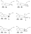
- FIGS. 9 a – 14 show various embodiments of the invention.
- FIG. 1 shows in simplified form a plan view of a complete rotor blade according to the invention.
- the rotor blade 10 is divided into two regions.
- the rotor blade 10 is of a conventional structure in its essential parts.
- That division 9 marks the region of the rotor blade 14 whose surface area can be reduced if required and can thus be withdrawn from the action of the wind thereon.
- FIG. 2 The fixed part of the rotor blade 10 , the surface area of which remains unchanged, is shown in FIG. 2 .
- the aerodynamically operative surface of the rotor blade 10 is markedly reduced, and thereby also the loading, particularly in extreme wind situations, is markedly less than in the case of a rotor blade which is constructed in conventional manner.
- FIG. 3 shows a simplified cross-sectional view of a first embodiment according to the invention.
- the rotor blade 10 is divided into a front region 11 and a rear box 14 .
- the rear box 14 comprises two webs of deformable material 18 which together with the rear wall 9 of the front region 11 form a closed container 16 .
- closed container 16 is filled under pressure with a gaseous medium the deformable material 18 forms a part (identified in FIG. 1 by reference numeral 14 ) of the surface, which is aerodynamically operative in normal operation, of the rotor blade 10 according to the invention.
- a suitable choice of the filling pressure affords such a stability in respect of that part of the rotor blade 10 that it deploys its normal action, under normal wind conditions.
- the wind pressure on that part of the rotor blade 10 is greater so that then the external pressure is higher than the internal pressure, and this therefore entails deformation of the rotor blade in the region of the rear box 14 and the rotor blade yields to the external wind pressure.
- the surface area on which that extreme wind acts is reduced and thus the loads on the subsequent structural components are reduced.
- this part of the rear box (in which the filling medium is disposed) can be actively emptied for example when a predetermined wind speed is exceeded, in order to reduce the surface area of the rotor blade. That active emptying has the advantage that the shape of the rotor blade is defined at any time while indefinite situations can occur when the rear box yields as a consequence of the external pressure.
- a pressure relief valve (not shown) through which an increased pressure formed in the container 16 can escape.
- the pressure required for normal operation can be restored by the use of a compressor 17 . If moreover controllable valves and/or pressure sensors (also not shown) are provided, the filling pressure in the container 16 can also be consequentially adjusted in the event of fluctuations in the wind pressure in order always to maintain optimum operating conditions in that way.
- FIG. 4 shows a second embodiment of the present invention, in which the surface of the suction side of the rotor blade 10 is prolonged, instead of involving a complete rear box 14 . That prolongation is a surface element 24 which adjoins the surface of the front region 11 .
- the surface element 24 can be displaced in the direction of the arrow. That displacement can be effected for example hydraulically, namely with suitable hydraulic cylinders, pneumatically, with pneumatic cylinders, by electrical drives, or in another suitable fashion. It will be appreciated that suitable pumps, compressors or drives (actuators) have to be provided for that purpose, but they are not shown in the Figure for the sake of simplicity.
- such displacement can take place into the front region so that the surface of the front region 11 covers over the surface element 24 .
- the displacement can also take place on the surface of the front region 11 so that the surface element 24 in turn covers over the corresponding part of the surface of the front region 11 . In both cases this involves a reduction in the aerodynamically operative surface of the rotor blade 10 .
- FIGS. 5 a and 5 b A third embodiment of the present invention is shown in FIGS. 5 a and 5 b .
- FIG. 5 a shows a winding 20 of a deformable material and reference numeral 30 denotes folding arms which are in the folded condition.
- the mechanism here can be comparable to that of an awning.
- FIG. 5 b shows this embodiment in the condition involved in normal operation.
- the folding arms 30 are extended and, as the deformable material 18 is secured thereto, it was unwound from the coil 20 upon extension of the folding arms 30 so that the winding core 21 now no longer carries the entire winding of material.
- the deformable material 18 is secured on the one hand to the winding core 21 and on the other hand to the ends of the folding arms 30 , which face towards the right in the Figure.
- Those ends of the folding arms 30 can in turn be connected by a bar (not shown) in order on the one hand to achieve a higher level of strength for the structure and on the other hand to fix the deformable material there.
- a reduction in the operative surface area takes place in the reverse fashion: the folding arms 30 and the scissor trellis arrangement (not shown) are retracted (folded) and at the same time the deformable material 18 is wound on the winding core 21 so that finally the winding core 20 is again in the condition shown in FIG. 5 a and the operative surface area of the rotor blade 10 is reduced.
- the surface element 24 is mounted pivotably at the rear side of the front region 11 and thus prolongs the suction side of that front region 11 .
- the surface element 24 is supported by a compression spring 28 disposed between the surface element 24 and the carrier structure of the front region 11 .
- compression spring 28 supports the surface element 24 in such a way that it retains the desired position. If now there is a wind pressure on the top side of the rotor blade 10 , beyond the normal operating conditions, the pressure on the surface of the surface element 24 rises and overcomes the force of the spring 28 so that the surface element 24 is pressed downwardly in FIG. 6 and therefore yields to the wind pressure and thus the aerodynamically operative surface area is correspondingly reduced.
- FIG. 7 shows a fifth embodiment of the invention.
- the surface element 24 instead of the surface element 24 being pivotably mounted to the rear side of the front region 11 , the surface element 24 is arranged on a pivot spindle 22 which is rotatable about its own longitudinal axis. In the position shown in FIG. 7 the surface element 24 again prolongs the aerodynamically operative surface of the rotor blade 10 .
- the pivot spindle 22 with the surface element 24 secured thereto is rotated about its longitudinal axis in such a way that the outer end of the surface element 24 moves in one of the two directions indicated by the double-headed arrow. That in turn results in a reduction in the aerodynamically operative surface area of the rotor blade 10 and, concomitantly therewith, a variation in the wind load on the rotor blade 10 and all subsequent components of the wind power installation.
- FIGS. 8 a and 8 b A variant of the embodiment shown in FIG. 7 is illustrated in FIGS. 8 a and 8 b .
- the surface element denoted by reference 24 in FIG. 7 is divided in FIG. 8 a into three blade-like or lamellar elements 26 . They are deliberately shown in FIG. 8 a at a spacing in order to clearly show that division.
- those three elements are arranged in such a way that they forth a surface which is as closed as possible and which in turn as smoothly as possible adjoins the front region 11 of the rotor blade 10 .
- Each of the blades 26 is arranged on its own pivot spindle.
- Each of those pivot spindles 28 is rotatable about its own longitudinal axis and thus permits pivotal movement of the blades 26 by rotation of the pivot spindle 28 about the longitudinal axis.
- FIG. 8 b shows the apparatus according to the invention in the situation in which the blades are pivoted in such a way that the aerodynamically operative surface of the rotor blade 10 is reduced.
- the blades 26 are pivoted into the flow shadow of the front region 11 .
- the size of the surface area can be reduced at a wind speed of above 20 m/s so that the size of the surface area decreases markedly, as shown in FIG. 2 .
- the control system is preferably computer-aided and if necessary provides for the respectively optimally set surface area for the rotor blade.
- FIGS. 9 a to 14 show further alternative or supplemental embodiments in relation to preceding FIGS. 3 to 8 b.
- FIG. 14 shows a further structural variant of a rotor blade according to the invention.
- the structure is built up by pivotable loops 32 which can be covered by a film which is again deformable, and are mounted pivotably at mounting points 34 .
- pivotable loops 32 which can be covered by a film which is again deformable, and are mounted pivotably at mounting points 34 .
- FIG. 11 b (FIG 11 a substantially corresponds to FIG. 6 ), as a supplemental consideration in relation to FIG. 6 , shows an element 25 at the pressure side.
- the elements 24 and 25 must hang together at the trailing edge of the blade so that they are pivotable about a pivot mounting point 26 . Under some circumstances it is appropriate with this structure to provide for overlapping by the rotor blade box 11 over the element 25 along the length of the rotor blade.
- FIG. 12 b (an enlargement of what is shown in FIG. 7 and FIG. 12 a respectively) also illustrates a pressure-side element 25 which in the illustrated case is fixed by way of a mechanical connection like the suction-side element 24 to a common shaft 12 .
- FIGS. 13 a and 13 b show a development of what is already illustrated in FIGS. 8 a and 8 b .
- specific shafts 28 are illustrated for corresponding elements on the pressure side.
- FIG. 13 a shows a rotor blade in normal operation.
- FIG. 13 b shows a situation in which the rear box is no longer operative, by virtue of corresponding rotation or by virtue of displacement of the shafts 28 .
Landscapes
- Engineering & Computer Science (AREA)
- Life Sciences & Earth Sciences (AREA)
- Sustainable Development (AREA)
- Sustainable Energy (AREA)
- Chemical & Material Sciences (AREA)
- Combustion & Propulsion (AREA)
- Mechanical Engineering (AREA)
- General Engineering & Computer Science (AREA)
- Physics & Mathematics (AREA)
- Fluid Mechanics (AREA)
- Wind Motors (AREA)
Applications Claiming Priority (5)
| Application Number | Priority Date | Filing Date | Title |
|---|---|---|---|
| DE10064912.2A DE10064912B4 (de) | 2000-12-23 | 2000-12-23 | Rotorblatt für eine Windenergieanlage |
| DE10064912.2 | 2000-12-23 | ||
| DE10152449A DE10152449A1 (de) | 2001-10-26 | 2001-10-26 | Rotorblatt für eine Windenergieanlage |
| DE10152449.8 | 2001-10-26 | ||
| PCT/EP2001/015106 WO2002051730A2 (de) | 2000-12-23 | 2001-12-20 | Rotorblatt für eine windenergieanlage |
Publications (2)
| Publication Number | Publication Date |
|---|---|
| US20040105752A1 US20040105752A1 (en) | 2004-06-03 |
| US7204674B2 true US7204674B2 (en) | 2007-04-17 |
Family
ID=26008086
Family Applications (1)
| Application Number | Title | Priority Date | Filing Date |
|---|---|---|---|
| US10/451,753 Expired - Lifetime US7204674B2 (en) | 2000-12-23 | 2001-12-20 | Rotor blade for a wind power installation |
Country Status (15)
| Country | Link |
|---|---|
| US (1) | US7204674B2 (tr) |
| EP (1) | EP1350027B1 (tr) |
| JP (1) | JP4020783B2 (tr) |
| KR (1) | KR100614102B1 (tr) |
| CN (1) | CN100365271C (tr) |
| AU (1) | AU2002235802B2 (tr) |
| BR (1) | BR0116502B1 (tr) |
| CA (1) | CA2432556C (tr) |
| CY (1) | CY1113626T1 (tr) |
| DK (1) | DK1350027T3 (tr) |
| ES (1) | ES2397263T3 (tr) |
| NZ (1) | NZ526588A (tr) |
| PT (1) | PT1350027E (tr) |
| TR (1) | TR200700949A2 (tr) |
| WO (1) | WO2002051730A2 (tr) |
Cited By (26)
| Publication number | Priority date | Publication date | Assignee | Title |
|---|---|---|---|---|
| US20070036657A1 (en) * | 2003-04-28 | 2007-02-15 | Aloys Wobben | Rotor blade for a wind power system |
| US20070297896A1 (en) * | 2002-06-05 | 2007-12-27 | Aloys Wobben | Rotor blade for a wind power plant |
| US20090285682A1 (en) * | 2008-05-16 | 2009-11-19 | Frontier Wind, Llc | Wind Turbine With Deployable Air Deflectors |
| US20090284016A1 (en) * | 2008-05-16 | 2009-11-19 | Frontier Wind, Llc | Wind turbine with gust compensating air deflector |
| US20100028161A1 (en) * | 2008-08-01 | 2010-02-04 | Vestas Wind Systems A/S | Segmented Rotor Blade Extension Portion |
| US20100028162A1 (en) * | 2008-08-01 | 2010-02-04 | Vestas Wind Systems A/S | Rotor blade extension portion having a skin located over a framework |
| US20110142681A1 (en) * | 2010-07-21 | 2011-06-16 | General Electric Company | Rotor blade assembly |
| US20110223021A1 (en) * | 2010-03-10 | 2011-09-15 | Vestas Wind Systems A/S | Wind turbine rotor blade |
| US20110268557A1 (en) * | 2010-09-29 | 2011-11-03 | General Electric Company | System and method for attenuating the noise of airfoils |
| US20110293420A1 (en) * | 2008-10-14 | 2011-12-01 | Vestas Wind Systems A/S | Wind turbine blade with device for changing the aerodynamic surface or shape |
| US20120009064A1 (en) * | 2010-07-06 | 2012-01-12 | Lm Glasfiber A/S | Wind turbine blade with variable trailing edge |
| EP2504570A2 (en) * | 2009-11-25 | 2012-10-03 | Vestas Wind Systems A/S | Flap control for wind turbine blades |
| US20120292916A1 (en) * | 2010-02-05 | 2012-11-22 | Shandong Zhongtai New Energy Group Co., Ltd | Wind power generating apparatus and wind blade structure |
| US20130067798A1 (en) * | 2011-09-19 | 2013-03-21 | Steve KELTNER | Fly repeller |
| US20130170990A1 (en) * | 2011-12-28 | 2013-07-04 | Orville J. Birkestrand | Power generation apparatus |
| US20140140846A1 (en) * | 2011-12-28 | 2014-05-22 | Orville J. Birkestrand | Power generation apparatus |
| KR101434469B1 (ko) * | 2013-04-29 | 2014-08-26 | 삼성중공업 주식회사 | 풍력 발전장치용 블레이드 |
| US20140334930A1 (en) * | 2011-12-22 | 2014-11-13 | Lm Wp Patent Holding A/S | Wind turbine blade assembled from inboard part and outboard part having different types of load carrying structures |
| US20160084223A1 (en) * | 2014-09-19 | 2016-03-24 | Siemens Aktiengesellschaft | Lift influencing device for a rotor blade of a wind turbine |
| US10507902B2 (en) | 2015-04-21 | 2019-12-17 | General Electric Company | Wind turbine dome and method of assembly |
| US11231009B2 (en) * | 2017-03-07 | 2022-01-25 | Siemens Gamesa Renewable Energy A/S | Safety system for an aerodynamic device of a wind turbine rotor blade |
| US11274649B2 (en) * | 2017-03-07 | 2022-03-15 | Siemens Gamesa Renewable Energy A/S | Pressure supply system for a pneumatically activatable aerodynamic device of a rotor blade of a wind turbine |
| US11384734B1 (en) | 2017-04-07 | 2022-07-12 | Orville J. Birkestrand | Wind turbine |
| US11428204B2 (en) | 2017-10-24 | 2022-08-30 | Wobben Properties Gmbh | Rotor blade of a wind turbine and method for designing same |
| US20230287863A1 (en) * | 2020-07-07 | 2023-09-14 | Lm Wp Patent Holding A/S | Rotor blade assembly for mitigating stall-induced vibrations |
| US11781521B2 (en) | 2020-02-27 | 2023-10-10 | Orville J. Birkestrand | Toroidal lift force engine |
Families Citing this family (28)
| Publication number | Priority date | Publication date | Assignee | Title |
|---|---|---|---|---|
| AU2004225883B2 (en) * | 2003-03-31 | 2010-06-17 | Technical University Of Denmark | Control of power, loads and/or stability of a horizontal axis wind turbine by use of variable blade geometry control |
| CN101351640B (zh) * | 2005-10-17 | 2012-07-04 | 维斯塔斯风力系统有限公司 | 具有可变空气动力学轮廓的风轮机叶片 |
| NL1031223C1 (nl) * | 2006-02-23 | 2007-08-24 | Stichting Nationaal Lucht En R | Reductie van windturbinegeluid door borstels op de achterrand van de bladen. |
| BRPI0600613B1 (pt) * | 2006-03-14 | 2015-08-11 | Tecsis Tecnologia E Sist S Avançados S A | Pá multielementos com perfis aerodinâmicos |
| DE102006022279B4 (de) * | 2006-05-11 | 2016-05-12 | Aloys Wobben | Rotorblatt für eine Windenergieanlage |
| US8419363B2 (en) | 2006-07-07 | 2013-04-16 | Danmarks Tekniske Universitet | Variable trailing edge section geometry for wind turbine blade |
| KR100809620B1 (ko) * | 2007-01-31 | 2008-03-05 | 장길훈 | 풍력 발전용 풍차 |
| WO2008131800A1 (en) | 2007-04-30 | 2008-11-06 | Vestas Wind Systems A/S | A wind turbine blade |
| US9039372B2 (en) | 2007-04-30 | 2015-05-26 | Vestas Wind Systems A/S | Wind turbine blade |
| ES2324002B1 (es) * | 2007-06-22 | 2010-05-13 | GAMESA INNOVATION & TECHNOLOGY, S.L. | Pala de aerogenerador con alerones deflectables. |
| ES2326352B1 (es) * | 2007-09-14 | 2010-07-15 | GAMESA INNOVATION & TECHNOLOGY, S.L. | Pala de aerogenerador con alerones deflectables controlados por cambios de la presion en la superficie. |
| KR100915623B1 (ko) * | 2007-11-30 | 2009-09-07 | 이종배 | 날개의 폭 조절이 가능한 풍차 |
| GB2459453B (en) * | 2008-04-21 | 2011-06-08 | Barry Robert Marshall | Energy output limiter for wind turbine rotor(s) |
| DE102009009272B4 (de) * | 2009-02-17 | 2013-02-28 | Siemens Aktiengesellschaft | Qualitätsprüfung für Rotorblätter einer Windenergieanlage |
| EP2404055B1 (en) * | 2009-03-06 | 2016-10-12 | Vestas Wind Systems A/S | A wind turbine providing increased power output |
| WO2011026495A2 (en) * | 2009-09-04 | 2011-03-10 | Vestas Wind Systems A/S | Wind turbine rotor blade |
| NL2003896C2 (nl) * | 2009-12-02 | 2011-06-06 | Emergya Wind Technologies Holdings N V | Windturbineblad met variabel oppervlak en daarmee uitgeruste windturbine. |
| US20130224024A1 (en) * | 2010-09-01 | 2013-08-29 | Vestas Wind Systems A/S | Rotor blade for wind turbine with movable control surface |
| GB201109412D0 (en) * | 2011-06-03 | 2011-07-20 | Blade Dynamics Ltd | A wind turbine rotor |
| WO2013045601A1 (en) * | 2011-09-29 | 2013-04-04 | Lm Wind Power A/S | A wind turbine blade |
| US10677217B2 (en) * | 2012-10-03 | 2020-06-09 | General Electric Company | Wind turbine and method of operating the same |
| CN104234941A (zh) * | 2013-06-24 | 2014-12-24 | 王智勇 | 一种可折叠的风力发电机桨叶 |
| KR101497343B1 (ko) * | 2013-10-10 | 2015-03-02 | 삼성중공업 주식회사 | 블레이드 |
| DK2908001T3 (da) * | 2014-02-12 | 2017-01-02 | Siemens Ag | Midler til dæmpning af belastning på en vindmøllerotorvinge |
| DE102015206430A1 (de) * | 2015-04-10 | 2016-10-13 | Wobben Properties Gmbh | Rotorblatt einer Windenergieanlage |
| DE102015116634A1 (de) * | 2015-10-01 | 2017-04-06 | Wobben Properties Gmbh | Windenergieanlagen-Rotorblatt und Windenergieanlage |
| KR101628308B1 (ko) * | 2016-04-01 | 2016-06-08 | 손기태 | 수평축 풍력발전기용 가변 단면형 블레이드 |
| EP3667077A1 (en) * | 2018-12-13 | 2020-06-17 | Siemens Gamesa Renewable Energy A/S | Quick adaptation of wind turbine blade flow regulation |
Citations (43)
| Publication number | Priority date | Publication date | Assignee | Title |
|---|---|---|---|---|
| US1403069A (en) * | 1921-08-12 | 1922-01-10 | Burne Edward Lancaster | Means for regulating the speed of wind motors |
| US2400388A (en) * | 1944-03-17 | 1946-05-14 | Goodrich Co B F | Aerodynamic brake |
| US2428936A (en) * | 1943-09-10 | 1947-10-14 | Goodrich Co B F | Aerodynamic brake |
| US2442783A (en) * | 1944-07-01 | 1948-06-08 | Us Sec War | Turbine rotor |
| US2453403A (en) * | 1946-07-03 | 1948-11-09 | Charles E Bogardus | Windbreaker for parked aircraft |
| US2616509A (en) * | 1946-11-29 | 1952-11-04 | Thomas Wilfred | Pneumatic airfoil |
| US2622686A (en) * | 1942-07-21 | 1952-12-23 | Chevreau Rene Louis Pier Marie | Wind motor |
| US3184187A (en) * | 1963-05-10 | 1965-05-18 | Isaac Peter | Retractable airfoils and hydrofoils |
| US3463420A (en) * | 1968-02-28 | 1969-08-26 | North American Rockwell | Inflatable wing |
| US3874816A (en) * | 1973-10-23 | 1975-04-01 | Thomas E Sweeney | Windmill blade |
| FR2290585A1 (fr) * | 1974-11-07 | 1976-06-04 | Morin Bernard | Aile de rotor a profil variable, notamment pour eolienne |
| US3987984A (en) * | 1973-04-09 | 1976-10-26 | Albert George Fischer | Semi-rigid aircraft wing |
| SU577300A1 (ru) * | 1975-12-09 | 1977-10-25 | Свердловский Ордена Трудового Красного Знамени Горный Институт Им. В.В.Вахрушева | Лопатка турбомашины |
| JPS55153870A (en) * | 1979-05-18 | 1980-12-01 | Tomiji Takayama | Vane body for vertical-shaft windmill |
| US4247253A (en) * | 1977-07-07 | 1981-01-27 | Gakko Hojin Tokai University | Vertical axis wind turbine |
| US4274011A (en) * | 1980-03-14 | 1981-06-16 | Marvin Garfinkle | Wind turbine for marine propulsion |
| DE3126677A1 (de) | 1981-07-07 | 1983-01-20 | Erno-Raumfahrttechnik Gmbh, 2800 Bremen | "rotorblattausbildung fue schnellaufende rotoren" |
| US4498017A (en) | 1982-12-16 | 1985-02-05 | Parkins William E | Generating power from wind |
| JPS61140181A (ja) | 1984-12-12 | 1986-06-27 | Nec Corp | 半導体装置 |
| US4613760A (en) | 1984-09-12 | 1986-09-23 | The English Electric Company Limited | Power generating equipment |
| FR2587675A1 (fr) | 1985-09-24 | 1987-03-27 | Dumortier Paul | Ailerons a profils reversibles par autodeformation |
| US4692095A (en) * | 1984-04-26 | 1987-09-08 | Sir Henry Lawson-Tancred, Sons & Co. Ltd. | Wind turbine blades |
| EP0283730A1 (de) | 1987-03-14 | 1988-09-28 | Mtb Manövriertechnisches Büro | Von Luft oder Wasser umströmter Strömungskörper |
| SU1539378A1 (ru) * | 1988-03-29 | 1990-01-30 | Институт Электродинамики Ан Усср | Лопасть ветроколеса |
| DE3913505C2 (tr) * | 1989-04-25 | 1990-03-29 | Astrid 4050 Moenchengladbach De Holzem | |
| EP0375382A2 (en) | 1988-12-21 | 1990-06-27 | British Aerospace Public Limited Company | Wing flap aerodynamic noise suppression |
| US5096378A (en) * | 1989-01-17 | 1992-03-17 | Howden Wind Turbines Limited | Control of a wind turbine |
| JPH05180146A (ja) | 1991-12-27 | 1993-07-20 | Mitsubishi Heavy Ind Ltd | 風車過負荷防止装置 |
| US5320491A (en) * | 1992-07-09 | 1994-06-14 | Northern Power Systems, Inc. | Wind turbine rotor aileron |
| DE4002972C2 (de) | 1990-02-01 | 1994-06-16 | Guenter Waldherr | Tragflügel mit veränderbarem Profil, insbesondere zur Verwendung als Segel |
| DE4428731A1 (de) | 1994-08-15 | 1996-02-22 | Infan Gmbh Ingenieurgesellscha | Längenvariables Rotorblatt für Windkraftanlagen, insbesondere für Windkraftanlagen an Binnenlandstandorten |
| DE4435606A1 (de) | 1994-10-06 | 1996-04-11 | Manfred Dipl Ing Maibom | Flügel mit veränderbarer Form bezüglich der Wechselwirkung mit dem strömenden Medium |
| US5527151A (en) | 1992-03-04 | 1996-06-18 | Northern Power Systems, Inc. | Advanced wind turbine with lift-destroying aileron for shutdown |
| US5570997A (en) * | 1995-07-17 | 1996-11-05 | Pratt; Charles W. | Horizontal windmill with folding blades |
| US5570859A (en) * | 1995-01-09 | 1996-11-05 | Quandt; Gene A. | Aerodynamic braking device |
| GB2311978A (en) | 1996-04-10 | 1997-10-15 | Robert Pyatt | Adjustable wing |
| DE19719221C1 (de) | 1997-05-07 | 1998-10-29 | Roland Stelzer | Rotorblatt, insbesondere für Windkraftanlagen |
| US6015115A (en) * | 1998-03-25 | 2000-01-18 | Lockheed Martin Corporation | Inflatable structures to control aircraft |
| US6133716A (en) | 1998-10-23 | 2000-10-17 | Statordyne, Inc. | High-efficiency high-power uninterrupted power system |
| US6420795B1 (en) | 1998-08-08 | 2002-07-16 | Zond Energy Systems, Inc. | Variable speed wind turbine generator |
| US6465902B1 (en) | 2001-04-18 | 2002-10-15 | The United States Of America As Represented By The Secretary Of The Navy | Controllable camber windmill blades |
| US6523781B2 (en) * | 2000-08-30 | 2003-02-25 | Gary Dean Ragner | Axial-mode linear wind-turbine |
| US6682302B2 (en) * | 2001-03-20 | 2004-01-27 | James D. Noble | Turbine apparatus and method |
-
2001
- 2001-12-20 TR TR2007/00949A patent/TR200700949A2/tr unknown
- 2001-12-20 US US10/451,753 patent/US7204674B2/en not_active Expired - Lifetime
- 2001-12-20 WO PCT/EP2001/015106 patent/WO2002051730A2/de not_active Application Discontinuation
- 2001-12-20 NZ NZ526588A patent/NZ526588A/en not_active IP Right Cessation
- 2001-12-20 DK DK01985915.6T patent/DK1350027T3/da active
- 2001-12-20 EP EP01985915A patent/EP1350027B1/de not_active Expired - Lifetime
- 2001-12-20 CN CNB018216803A patent/CN100365271C/zh not_active Expired - Fee Related
- 2001-12-20 KR KR1020037008305A patent/KR100614102B1/ko active IP Right Grant
- 2001-12-20 CA CA002432556A patent/CA2432556C/en not_active Expired - Lifetime
- 2001-12-20 BR BRPI0116502-0A patent/BR0116502B1/pt not_active IP Right Cessation
- 2001-12-20 JP JP2002552837A patent/JP4020783B2/ja not_active Expired - Fee Related
- 2001-12-20 PT PT1985915T patent/PT1350027E/pt unknown
- 2001-12-20 ES ES01985915T patent/ES2397263T3/es not_active Expired - Lifetime
- 2001-12-20 AU AU2002235802A patent/AU2002235802B2/en not_active Ceased
-
2013
- 2013-01-04 CY CY20131100008T patent/CY1113626T1/el unknown
Patent Citations (43)
| Publication number | Priority date | Publication date | Assignee | Title |
|---|---|---|---|---|
| US1403069A (en) * | 1921-08-12 | 1922-01-10 | Burne Edward Lancaster | Means for regulating the speed of wind motors |
| US2622686A (en) * | 1942-07-21 | 1952-12-23 | Chevreau Rene Louis Pier Marie | Wind motor |
| US2428936A (en) * | 1943-09-10 | 1947-10-14 | Goodrich Co B F | Aerodynamic brake |
| US2400388A (en) * | 1944-03-17 | 1946-05-14 | Goodrich Co B F | Aerodynamic brake |
| US2442783A (en) * | 1944-07-01 | 1948-06-08 | Us Sec War | Turbine rotor |
| US2453403A (en) * | 1946-07-03 | 1948-11-09 | Charles E Bogardus | Windbreaker for parked aircraft |
| US2616509A (en) * | 1946-11-29 | 1952-11-04 | Thomas Wilfred | Pneumatic airfoil |
| US3184187A (en) * | 1963-05-10 | 1965-05-18 | Isaac Peter | Retractable airfoils and hydrofoils |
| US3463420A (en) * | 1968-02-28 | 1969-08-26 | North American Rockwell | Inflatable wing |
| US3987984A (en) * | 1973-04-09 | 1976-10-26 | Albert George Fischer | Semi-rigid aircraft wing |
| US3874816A (en) * | 1973-10-23 | 1975-04-01 | Thomas E Sweeney | Windmill blade |
| FR2290585A1 (fr) * | 1974-11-07 | 1976-06-04 | Morin Bernard | Aile de rotor a profil variable, notamment pour eolienne |
| SU577300A1 (ru) * | 1975-12-09 | 1977-10-25 | Свердловский Ордена Трудового Красного Знамени Горный Институт Им. В.В.Вахрушева | Лопатка турбомашины |
| US4247253A (en) * | 1977-07-07 | 1981-01-27 | Gakko Hojin Tokai University | Vertical axis wind turbine |
| JPS55153870A (en) * | 1979-05-18 | 1980-12-01 | Tomiji Takayama | Vane body for vertical-shaft windmill |
| US4274011A (en) * | 1980-03-14 | 1981-06-16 | Marvin Garfinkle | Wind turbine for marine propulsion |
| DE3126677A1 (de) | 1981-07-07 | 1983-01-20 | Erno-Raumfahrttechnik Gmbh, 2800 Bremen | "rotorblattausbildung fue schnellaufende rotoren" |
| US4498017A (en) | 1982-12-16 | 1985-02-05 | Parkins William E | Generating power from wind |
| US4692095A (en) * | 1984-04-26 | 1987-09-08 | Sir Henry Lawson-Tancred, Sons & Co. Ltd. | Wind turbine blades |
| US4613760A (en) | 1984-09-12 | 1986-09-23 | The English Electric Company Limited | Power generating equipment |
| JPS61140181A (ja) | 1984-12-12 | 1986-06-27 | Nec Corp | 半導体装置 |
| FR2587675A1 (fr) | 1985-09-24 | 1987-03-27 | Dumortier Paul | Ailerons a profils reversibles par autodeformation |
| EP0283730A1 (de) | 1987-03-14 | 1988-09-28 | Mtb Manövriertechnisches Büro | Von Luft oder Wasser umströmter Strömungskörper |
| SU1539378A1 (ru) * | 1988-03-29 | 1990-01-30 | Институт Электродинамики Ан Усср | Лопасть ветроколеса |
| EP0375382A2 (en) | 1988-12-21 | 1990-06-27 | British Aerospace Public Limited Company | Wing flap aerodynamic noise suppression |
| US5096378A (en) * | 1989-01-17 | 1992-03-17 | Howden Wind Turbines Limited | Control of a wind turbine |
| DE3913505C2 (tr) * | 1989-04-25 | 1990-03-29 | Astrid 4050 Moenchengladbach De Holzem | |
| DE4002972C2 (de) | 1990-02-01 | 1994-06-16 | Guenter Waldherr | Tragflügel mit veränderbarem Profil, insbesondere zur Verwendung als Segel |
| JPH05180146A (ja) | 1991-12-27 | 1993-07-20 | Mitsubishi Heavy Ind Ltd | 風車過負荷防止装置 |
| US5527151A (en) | 1992-03-04 | 1996-06-18 | Northern Power Systems, Inc. | Advanced wind turbine with lift-destroying aileron for shutdown |
| US5320491A (en) * | 1992-07-09 | 1994-06-14 | Northern Power Systems, Inc. | Wind turbine rotor aileron |
| DE4428731A1 (de) | 1994-08-15 | 1996-02-22 | Infan Gmbh Ingenieurgesellscha | Längenvariables Rotorblatt für Windkraftanlagen, insbesondere für Windkraftanlagen an Binnenlandstandorten |
| DE4435606A1 (de) | 1994-10-06 | 1996-04-11 | Manfred Dipl Ing Maibom | Flügel mit veränderbarer Form bezüglich der Wechselwirkung mit dem strömenden Medium |
| US5570859A (en) * | 1995-01-09 | 1996-11-05 | Quandt; Gene A. | Aerodynamic braking device |
| US5570997A (en) * | 1995-07-17 | 1996-11-05 | Pratt; Charles W. | Horizontal windmill with folding blades |
| GB2311978A (en) | 1996-04-10 | 1997-10-15 | Robert Pyatt | Adjustable wing |
| DE19719221C1 (de) | 1997-05-07 | 1998-10-29 | Roland Stelzer | Rotorblatt, insbesondere für Windkraftanlagen |
| US6015115A (en) * | 1998-03-25 | 2000-01-18 | Lockheed Martin Corporation | Inflatable structures to control aircraft |
| US6420795B1 (en) | 1998-08-08 | 2002-07-16 | Zond Energy Systems, Inc. | Variable speed wind turbine generator |
| US6133716A (en) | 1998-10-23 | 2000-10-17 | Statordyne, Inc. | High-efficiency high-power uninterrupted power system |
| US6523781B2 (en) * | 2000-08-30 | 2003-02-25 | Gary Dean Ragner | Axial-mode linear wind-turbine |
| US6682302B2 (en) * | 2001-03-20 | 2004-01-27 | James D. Noble | Turbine apparatus and method |
| US6465902B1 (en) | 2001-04-18 | 2002-10-15 | The United States Of America As Represented By The Secretary Of The Navy | Controllable camber windmill blades |
Cited By (45)
| Publication number | Priority date | Publication date | Assignee | Title |
|---|---|---|---|---|
| US20100232972A1 (en) * | 2002-06-05 | 2010-09-16 | Aloys Wobben | Rotor blade for a wind power plant |
| US20070297896A1 (en) * | 2002-06-05 | 2007-12-27 | Aloys Wobben | Rotor blade for a wind power plant |
| US8100663B2 (en) | 2002-06-05 | 2012-01-24 | Aloys Wobben | Rotor blade for a wind power plant |
| US7914261B2 (en) | 2002-06-05 | 2011-03-29 | Aloys Wobben | Rotor blade for a wind power plant |
| US7708530B2 (en) | 2002-06-05 | 2010-05-04 | Aloys Wobben | Rotor blade for a wind power plant |
| US20070036657A1 (en) * | 2003-04-28 | 2007-02-15 | Aloys Wobben | Rotor blade for a wind power system |
| US7946803B2 (en) | 2003-04-28 | 2011-05-24 | Aloys Wobben | Rotor blade for a wind power system |
| US8267654B2 (en) | 2008-05-16 | 2012-09-18 | Frontier Wind, Llc | Wind turbine with gust compensating air deflector |
| US10844837B2 (en) | 2008-05-16 | 2020-11-24 | Ge Infrastructure Technology, Llc | Wind turbine with deployable air deflectors |
| US20090284016A1 (en) * | 2008-05-16 | 2009-11-19 | Frontier Wind, Llc | Wind turbine with gust compensating air deflector |
| US20090285682A1 (en) * | 2008-05-16 | 2009-11-19 | Frontier Wind, Llc | Wind Turbine With Deployable Air Deflectors |
| US8192161B2 (en) | 2008-05-16 | 2012-06-05 | Frontier Wind, Llc. | Wind turbine with deployable air deflectors |
| US20100028162A1 (en) * | 2008-08-01 | 2010-02-04 | Vestas Wind Systems A/S | Rotor blade extension portion having a skin located over a framework |
| US20100028161A1 (en) * | 2008-08-01 | 2010-02-04 | Vestas Wind Systems A/S | Segmented Rotor Blade Extension Portion |
| US8393865B2 (en) | 2008-08-01 | 2013-03-12 | Vestas Wind Systems A/S | Rotor blade extension portion having a skin located over a framework |
| US8317479B2 (en) | 2008-08-01 | 2012-11-27 | Vestas Wind Systems A/S | Segmented rotor blade extension portion |
| US8899923B2 (en) * | 2008-10-14 | 2014-12-02 | Vestas Wind Systems A/S | Wind turbine blade with device for changing the aerodynamic surface or shape |
| US20110293420A1 (en) * | 2008-10-14 | 2011-12-01 | Vestas Wind Systems A/S | Wind turbine blade with device for changing the aerodynamic surface or shape |
| US20120269632A1 (en) * | 2009-11-25 | 2012-10-25 | Vestas Wind Systems A/S | Flap control for wind turbine blades |
| EP2504570A2 (en) * | 2009-11-25 | 2012-10-03 | Vestas Wind Systems A/S | Flap control for wind turbine blades |
| US20120292916A1 (en) * | 2010-02-05 | 2012-11-22 | Shandong Zhongtai New Energy Group Co., Ltd | Wind power generating apparatus and wind blade structure |
| US8847423B2 (en) * | 2010-02-05 | 2014-09-30 | Shandong Zhongtai New Energy Group Co., Ltd | Wind power generating apparatus and wind blade structure |
| US20110223021A1 (en) * | 2010-03-10 | 2011-09-15 | Vestas Wind Systems A/S | Wind turbine rotor blade |
| US8794919B2 (en) * | 2010-07-06 | 2014-08-05 | Lm Glasfiber A/S | Wind turbine blade with variable trailing edge |
| US20120009064A1 (en) * | 2010-07-06 | 2012-01-12 | Lm Glasfiber A/S | Wind turbine blade with variable trailing edge |
| US8011887B2 (en) | 2010-07-21 | 2011-09-06 | General Electric Company | Rotor blade assembly |
| US20110142681A1 (en) * | 2010-07-21 | 2011-06-16 | General Electric Company | Rotor blade assembly |
| US20110268557A1 (en) * | 2010-09-29 | 2011-11-03 | General Electric Company | System and method for attenuating the noise of airfoils |
| US20130067798A1 (en) * | 2011-09-19 | 2013-03-21 | Steve KELTNER | Fly repeller |
| US20140334930A1 (en) * | 2011-12-22 | 2014-11-13 | Lm Wp Patent Holding A/S | Wind turbine blade assembled from inboard part and outboard part having different types of load carrying structures |
| US10253751B2 (en) * | 2011-12-22 | 2019-04-09 | LM WP Patent Holdings A/S | Wind turbine blade assembled from inboard part and outboard part having different types of load carrying structures |
| US20140140846A1 (en) * | 2011-12-28 | 2014-05-22 | Orville J. Birkestrand | Power generation apparatus |
| US20130170990A1 (en) * | 2011-12-28 | 2013-07-04 | Orville J. Birkestrand | Power generation apparatus |
| US9816384B2 (en) * | 2011-12-28 | 2017-11-14 | Orville J. Birkestrand | Power generation apparatus |
| US9816383B2 (en) * | 2011-12-28 | 2017-11-14 | Orville J. Birkestrand | Power generation apparatus |
| KR101434469B1 (ko) * | 2013-04-29 | 2014-08-26 | 삼성중공업 주식회사 | 풍력 발전장치용 블레이드 |
| US10408192B2 (en) * | 2014-09-19 | 2019-09-10 | Siemens Gamesa Renewable Energy A/S | Lift influencing device for a rotor blade of a wind turbine |
| US20160084223A1 (en) * | 2014-09-19 | 2016-03-24 | Siemens Aktiengesellschaft | Lift influencing device for a rotor blade of a wind turbine |
| US10507902B2 (en) | 2015-04-21 | 2019-12-17 | General Electric Company | Wind turbine dome and method of assembly |
| US11231009B2 (en) * | 2017-03-07 | 2022-01-25 | Siemens Gamesa Renewable Energy A/S | Safety system for an aerodynamic device of a wind turbine rotor blade |
| US11274649B2 (en) * | 2017-03-07 | 2022-03-15 | Siemens Gamesa Renewable Energy A/S | Pressure supply system for a pneumatically activatable aerodynamic device of a rotor blade of a wind turbine |
| US11384734B1 (en) | 2017-04-07 | 2022-07-12 | Orville J. Birkestrand | Wind turbine |
| US11428204B2 (en) | 2017-10-24 | 2022-08-30 | Wobben Properties Gmbh | Rotor blade of a wind turbine and method for designing same |
| US11781521B2 (en) | 2020-02-27 | 2023-10-10 | Orville J. Birkestrand | Toroidal lift force engine |
| US20230287863A1 (en) * | 2020-07-07 | 2023-09-14 | Lm Wp Patent Holding A/S | Rotor blade assembly for mitigating stall-induced vibrations |
Also Published As
| Publication number | Publication date |
|---|---|
| ES2397263T3 (es) | 2013-03-05 |
| BR0116502A (pt) | 2004-02-03 |
| BR0116502B1 (pt) | 2009-12-01 |
| AU2002235802B2 (en) | 2006-06-22 |
| CA2432556A1 (en) | 2002-07-04 |
| EP1350027A2 (de) | 2003-10-08 |
| KR20030064848A (ko) | 2003-08-02 |
| US20040105752A1 (en) | 2004-06-03 |
| WO2002051730A3 (de) | 2002-11-07 |
| EP1350027B1 (de) | 2012-11-07 |
| CN100365271C (zh) | 2008-01-30 |
| CY1113626T1 (el) | 2016-06-22 |
| JP4020783B2 (ja) | 2007-12-12 |
| TR200700949A2 (tr) | 2007-10-22 |
| PT1350027E (pt) | 2013-01-24 |
| KR100614102B1 (ko) | 2006-08-22 |
| CN1511231A (zh) | 2004-07-07 |
| CA2432556C (en) | 2008-07-08 |
| DK1350027T3 (da) | 2013-02-04 |
| NZ526588A (en) | 2006-02-24 |
| WO2002051730A2 (de) | 2002-07-04 |
| JP2004520521A (ja) | 2004-07-08 |
Similar Documents
| Publication | Publication Date | Title |
|---|---|---|
| US7204674B2 (en) | Rotor blade for a wind power installation | |
| CA2683764C (en) | Rotor blade of a wind energy facility | |
| CA2634427C (en) | Actuation system for a wind turbine blade flap | |
| CN110582635B (zh) | 用于风力涡轮机的转子叶片的可气动地激活的气动装置的压力供应系统 | |
| EP1320680B1 (en) | Method for regulating a windmill and an apparatus for the use of said method | |
| JP5902738B2 (ja) | 空力ブレード上の負荷管理デバイス用作動機構 | |
| EP1630415A2 (en) | Foldable blades for wind turbines | |
| KR20140113510A (ko) | 공기역학적 블레이드상에 분포된 부하관리장치의 작동 | |
| KR20140113502A (ko) | 부하 보상장치용 자동 안전 시스템 | |
| US20230142969A1 (en) | Method and device for controlling a wind turbine to reduce noise | |
| WO2012095478A1 (en) | Wind turbine blade, wind turbine and method of controlling such |
Legal Events
| Date | Code | Title | Description |
|---|---|---|---|
| STCF | Information on status: patent grant |
Free format text: PATENTED CASE |
|
| FEPP | Fee payment procedure |
Free format text: PAYOR NUMBER ASSIGNED (ORIGINAL EVENT CODE: ASPN); ENTITY STATUS OF PATENT OWNER: LARGE ENTITY |
|
| FPAY | Fee payment |
Year of fee payment: 4 |
|
| FPAY | Fee payment |
Year of fee payment: 8 |
|
| MAFP | Maintenance fee payment |
Free format text: PAYMENT OF MAINTENANCE FEE, 12TH YEAR, LARGE ENTITY (ORIGINAL EVENT CODE: M1553); ENTITY STATUS OF PATENT OWNER: LARGE ENTITY Year of fee payment: 12 |