US7135082B2 - Method of making a power transmission belt/belt sleeve and belt/belt sleeve made according to the method - Google Patents
Method of making a power transmission belt/belt sleeve and belt/belt sleeve made according to the method Download PDFInfo
- Publication number
- US7135082B2 US7135082B2 US10/600,967 US60096703A US7135082B2 US 7135082 B2 US7135082 B2 US 7135082B2 US 60096703 A US60096703 A US 60096703A US 7135082 B2 US7135082 B2 US 7135082B2
- Authority
- US
- United States
- Prior art keywords
- belt
- belt sleeve
- forming
- sleeve component
- rubber layer
- Prior art date
- Legal status (The legal status is an assumption and is not a legal conclusion. Google has not performed a legal analysis and makes no representation as to the accuracy of the status listed.)
- Expired - Lifetime, expires
Links
- 230000005540 biological transmission Effects 0.000 title claims abstract description 48
- 238000000034 method Methods 0.000 title claims abstract description 30
- 238000004519 manufacturing process Methods 0.000 title claims abstract description 27
- 229920001971 elastomer Polymers 0.000 claims abstract description 127
- 230000006835 compression Effects 0.000 claims abstract description 55
- 238000007906 compression Methods 0.000 claims abstract description 55
- 238000005304 joining Methods 0.000 claims abstract description 23
- 239000000835 fiber Substances 0.000 claims description 29
- 230000000712 assembly Effects 0.000 claims description 16
- 238000000429 assembly Methods 0.000 claims description 16
- 230000015572 biosynthetic process Effects 0.000 claims description 10
- 239000012530 fluid Substances 0.000 claims description 9
- 238000010438 heat treatment Methods 0.000 claims description 8
- 238000010030 laminating Methods 0.000 claims description 5
- 238000005520 cutting process Methods 0.000 claims description 3
- 238000004073 vulcanization Methods 0.000 description 7
- 239000000463 material Substances 0.000 description 4
- 229920001778 nylon Polymers 0.000 description 3
- 229920000728 polyester Polymers 0.000 description 3
- 229920006231 aramid fiber Polymers 0.000 description 2
- 230000000295 complement effect Effects 0.000 description 2
- 238000010276 construction Methods 0.000 description 2
- 239000012809 cooling fluid Substances 0.000 description 2
- 238000001125 extrusion Methods 0.000 description 2
- 239000000314 lubricant Substances 0.000 description 2
- 230000007246 mechanism Effects 0.000 description 2
- 238000003825 pressing Methods 0.000 description 2
- 239000012783 reinforcing fiber Substances 0.000 description 2
- OKTJSMMVPCPJKN-UHFFFAOYSA-N Carbon Chemical compound [C] OKTJSMMVPCPJKN-UHFFFAOYSA-N 0.000 description 1
- 229920000181 Ethylene propylene rubber Polymers 0.000 description 1
- 229920000459 Nitrile rubber Polymers 0.000 description 1
- 239000004677 Nylon Substances 0.000 description 1
- 239000004760 aramid Substances 0.000 description 1
- 229920003235 aromatic polyamide Polymers 0.000 description 1
- YACLQRRMGMJLJV-UHFFFAOYSA-N chloroprene Chemical compound ClC(=C)C=C YACLQRRMGMJLJV-UHFFFAOYSA-N 0.000 description 1
- 230000002301 combined effect Effects 0.000 description 1
- 238000004891 communication Methods 0.000 description 1
- 239000000498 cooling water Substances 0.000 description 1
- 239000013078 crystal Substances 0.000 description 1
- 238000009826 distribution Methods 0.000 description 1
- 230000000694 effects Effects 0.000 description 1
- 230000030279 gene silencing Effects 0.000 description 1
- 229910002804 graphite Inorganic materials 0.000 description 1
- 239000010439 graphite Substances 0.000 description 1
- 238000003475 lamination Methods 0.000 description 1
- 229910052751 metal Inorganic materials 0.000 description 1
- 239000002184 metal Substances 0.000 description 1
- CWQXQMHSOZUFJS-UHFFFAOYSA-N molybdenum disulfide Chemical compound S=[Mo]=S CWQXQMHSOZUFJS-UHFFFAOYSA-N 0.000 description 1
- 229910052982 molybdenum disulfide Inorganic materials 0.000 description 1
- 238000000465 moulding Methods 0.000 description 1
- -1 polytetrafluoroethylene Polymers 0.000 description 1
- 229920001343 polytetrafluoroethylene Polymers 0.000 description 1
- 239000004810 polytetrafluoroethylene Substances 0.000 description 1
- 239000007787 solid Substances 0.000 description 1
- 230000003746 surface roughness Effects 0.000 description 1
- 239000002699 waste material Substances 0.000 description 1
- XLYOFNOQVPJJNP-UHFFFAOYSA-N water Substances O XLYOFNOQVPJJNP-UHFFFAOYSA-N 0.000 description 1
- 230000037303 wrinkles Effects 0.000 description 1
Images


Classifications
-
- F—MECHANICAL ENGINEERING; LIGHTING; HEATING; WEAPONS; BLASTING
- F16—ENGINEERING ELEMENTS AND UNITS; GENERAL MEASURES FOR PRODUCING AND MAINTAINING EFFECTIVE FUNCTIONING OF MACHINES OR INSTALLATIONS; THERMAL INSULATION IN GENERAL
- F16G—BELTS, CABLES, OR ROPES, PREDOMINANTLY USED FOR DRIVING PURPOSES; CHAINS; FITTINGS PREDOMINANTLY USED THEREFOR
- F16G5/00—V-belts, i.e. belts of tapered cross-section
- F16G5/04—V-belts, i.e. belts of tapered cross-section made of rubber
- F16G5/06—V-belts, i.e. belts of tapered cross-section made of rubber with reinforcement bonded by the rubber
-
- B—PERFORMING OPERATIONS; TRANSPORTING
- B29—WORKING OF PLASTICS; WORKING OF SUBSTANCES IN A PLASTIC STATE IN GENERAL
- B29D—PRODUCING PARTICULAR ARTICLES FROM PLASTICS OR FROM SUBSTANCES IN A PLASTIC STATE
- B29D29/00—Producing belts or bands
- B29D29/08—Toothed driving belts
-
- B—PERFORMING OPERATIONS; TRANSPORTING
- B29—WORKING OF PLASTICS; WORKING OF SUBSTANCES IN A PLASTIC STATE IN GENERAL
- B29D—PRODUCING PARTICULAR ARTICLES FROM PLASTICS OR FROM SUBSTANCES IN A PLASTIC STATE
- B29D29/00—Producing belts or bands
- B29D29/10—Driving belts having wedge-shaped cross-section
- B29D29/103—Multi-ribbed driving belts
-
- F—MECHANICAL ENGINEERING; LIGHTING; HEATING; WEAPONS; BLASTING
- F16—ENGINEERING ELEMENTS AND UNITS; GENERAL MEASURES FOR PRODUCING AND MAINTAINING EFFECTIVE FUNCTIONING OF MACHINES OR INSTALLATIONS; THERMAL INSULATION IN GENERAL
- F16G—BELTS, CABLES, OR ROPES, PREDOMINANTLY USED FOR DRIVING PURPOSES; CHAINS; FITTINGS PREDOMINANTLY USED THEREFOR
- F16G5/00—V-belts, i.e. belts of tapered cross-section
- F16G5/20—V-belts, i.e. belts of tapered cross-section with a contact surface of special shape, e.g. toothed
Definitions
- This invention relates to power transmission belts/belt sleeves and, more particularly, to a belt/belt sleeve having at least one of a) ribs and b) a plurality of cog teeth thereon.
- the invention is further directed to a method of making such a power transmission belt/belt sleeve.
- JP-UM-B-27946/1982 Publication a process is disclosed wherein an unvulcanized belt sleeve, having the aforementioned joined, compression rubber layer and cushion rubber layer with at least one load carrying member embedded therein, is inserted into a cylindrical metal die assembly.
- the compression layer resides against an outer, radially inwardly facing mold surface having formed rib grooves thereon.
- the ribs are formed in the belt sleeve by pressing the compression rubber layer radially outwardly against the ribbed mold surface.
- an unvulcanized belt sleeve having an unformed compression rubber layer laminated outside of a cushion rubber layer in which at least one load carrying member is embedded.
- the unvulcanized belt sleeve is fit around an inner die element which is expandable in a radial direction.
- the inner die element, with the unvulcanized belt sleeve fit thereto, is placed in an outer die element with a radially inwardly facing surface in which rib grooves are formed.
- ribs are formed by urging the compression rubber layer radially outwardly into conforming relationship with the grooved, outer die element surface.
- JP-A-86236/1998 Publication a process is disclosed wherein exposed portions of the ribs, formed as described in the publications in the prior paragraph, are removed by grinding, thereby exposing short fibers embedded in the compression layer.
- Japanese Patent Publication No. 2708717 also inherently has some potential drawbacks. Because the ribs are formed through an extrusion process in a lengthwise direction, the rubber in the compression layer may not fill the mold with a uniform density to consistently produce a precise rib shape with a homogeneous composition. That is, the flow of the rubber in the compression layer may not be uniform, particularly in the direction transversely to the length of the belt sleeve/ribs.
- the invention is directed to a method of making a power transmission belt/belt sleeve having a body with a continuous length extending around an axis, an inside, an outside spaced radially from the inside, and at least one of a) a plurality of ribs extending lengthwise and b) a plurality of cog teeth spaced at lengthwise intervals, on one of the inside and outside of the belt/belt sleeve.
- the method includes the steps of: forming a first belt/belt sleeve component with a compression rubber layer; applying a radial force on the first belt/belt sleeve component so as to urge the first belt/belt sleeve component against a mold surface and thereby forming the at least one of the plurality of ribs and plurality of cog teeth in the first belt/belt sleeve component; forming a second belt/belt sleeve component having at least a part of a cushion rubber layer and a load carrying member; and after forming the at least one of the plurality of ribs and plurality of cog teeth on the first belt/belt sleeve component, joining the first and second belt/belt sleeve components to each other.
- the step of applying a radial force involves applying a force on the first belt/belt sleeve component in a radially outward direction.
- the step of joining the first and second belt/belt sleeve components involves laminating the first and second belt/belt sleeve components while exerting a force on the second belt/belt sleeve component in a radially outward direction.
- the step of forming the first belt/belt sleeve component involves providing short fibers, each with lengths, in the compression rubber layer so that the lengths of the short fibers are oriented to extend generally in an axial direction.
- the step of forming the first belt/belt sleeve component may involve joining a second part of the cushion rubber layer to the compression rubber layer.
- the step of joining the second part of the cushion rubber layer involves joining the second part of the cushion rubber layer at a radially inside location on the compression rubber layer and the step of forming the second belt/belt sleeve component involves joining the load carrying member at a radially outside location on the at least part of the cushion rubber layer.
- the step of forming the at least one of the plurality of ribs and plurality of cog teeth involves forming the at least one of the plurality of ribs and plurality of cog teeth against the mold surface on a first mold assembly.
- the step of forming the second belt/belt sleeve component may involve forming the second belt/belt sleeve component against a second mold assembly.
- the step of joining the first and second belt/belt sleeve components may in turn involve joining the first and second belt/belt sleeve components with the first and second mold assemblies residing one within the other.
- the step of forming the second belt/belt sleeve component involves forming the second belt/belt sleeve component with the second mold assembly separated from the first mold assembly.
- the step of forming the at least one of the plurality of ribs and plurality of cog teeth against the first mold assembly involves forming the at least one of the plurality of ribs and plurality of cog teeth with the first and second mold assemblies residing one within the other.
- the step of forming the at least one of the plurality of ribs and plurality of cog teeth involves the steps of providing a bladder assembly with a bladder element between the first and second mold assemblies, and repositioning the bladder element so that the bladder element applies a radially outwardly directed force on the first belt/belt sleeve component.
- the step of applying a radial force on the first belt/belt sleeve component involves generating a low pressure region that causes a suction force to be developed through the mold surface that urges the first belt/belt sleeve component against the mold surface.
- the step of providing a bladder assembly may involve providing a bladder assembly on the second mold assembly.
- the step of repositioning the bladder element may involve directing a fluid under pressure against the bladder element.
- the method may further involve the step of heating the mold surface as the radial force is applied to the first belt/belt sleeve component to facilitate formation of the at least one of the plurality of ribs and plurality of cog teeth.
- the method may further include the step of cutting the belt/belt sleeve to produce a power transmission belt having a desired width.
- the step of forming the second belt/belt sleeve component involves forming the entire cushion rubber layer as a part of the second belt/belt sleeve component.
- the invention further contemplates a power transmission belt made according to the method, described above.
- the invention is further directed to a power transmission belt having an endless body with a length, an inside, an outside, and laterally spaced sides.
- the endless body has a compression rubber layer, a cushion rubber layer, and at least one load carrying member embedded in the cushion rubber layer.
- the endless body further has at least one of a) at least one rib extending in a lengthwise direction and b) a plurality of cog teeth spaced at lengthwise intervals.
- the rubber in the at least one of the at least one rib and plurality of cog teeth has a flow state during formation of the at least one of the at least one rib and plurality of cog teeth.
- the at least part of the cushion rubber layer is unaffected by the flow state induced during formation of the at least one of the at least one rib and plurality of cog teeth.
- the at least one load carrying member has a rate of elongation less than or equal to 1.5%.
- the at least one load carrying member has a rate of elongation less than or equal to 1.2%.
- the lengths of the plurality of fibers are generally oriented to extend at angles, and preferably right angles, to the length of the body.
- a plurality of short fibers may be embedded in the compression rubber layer.
- the flow state is induced by pressure application during formation in a direction between the inside and outside of the body.
- a part of the cushion rubber layer is affected by the flow state induced during formation of the at least one of the at least one rib and plurality of cog teeth.
- FIG. 1 is a fragmentary, cross-sectional, perspective view of a power transmission belt, made according to the present invention, and having a plurality of ribs extending in a likewise direction;
- FIG. 2 is a fragmentary, cross-sectional view of a die system consisting of first and second cooperating die assemblies, useable to make power transmission belts, according to the present invention, and with the first and second die assemblies residing, one within the other;
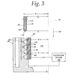
- FIG. 3 is a fragmentary, cross-sectional view of the first die assembly in FIG. 2 and with a first belt sleeve component placed in an operative position relative to the first die assembly;
- FIG. 4 is a view corresponding to that in FIG. 3 and with the second die assembly in FIG. 2 placed within the first die assembly and with the first belt sleeve component being urged against a mold surface on the first die assembly to form ribs thereon;
- FIG. 5 is a view as in FIG. 4 with the first belt sleeve component substantially fully formed against the mold surface on the first die assembly;
- FIG. 6 is a fragmentary, cross-sectional view of the second die assembly with a second belt sleeve component thereon;
- FIG. 7 is a view as in FIG. 5 , with the second belt sleeve component on the second die assembly;
- FIG. 8 is a view as in FIG. 7 with the second belt sleeve component urged against, and laminated to, the first belt sleeve component;
- FIG. 9 is a fragmentary, cross-sectional, perspective view of another form of power transmission belt, made according to the present invention, and having cog teeth spaced at lengthwise intervals;
- FIG. 10 is a schematic representation of a modified form of die system for producing the power transmission belt of FIG. 9 ;
- FIG. 11 is a cross-sectional view of another form of power transmission belt, in the form of a V-belt, made according to the present invention.
- FIG. 1 a V-ribbed, power transmission belt, made according to the present invention, is shown at 10 .
- the belt 10 has a body 12 with an inside 14 and an outside 16 .
- the body 12 has a length, as indicated by the double-headed arrow L, and a lateral extent between side surfaces 18 , 20 .
- the body 12 has a cushion rubber layer 22 which is laminated to a compression rubber layer 24 .
- Load carrying members 26 extending lengthwise of the body 12 , are embedded in the cushion rubber layer 22 .
- a plurality of longitudinally extending, and laterally spaced, ribs 28 are formed in the compression rubber layer 24 .
- the number of ribs 28 shown as three in this embodiment, may vary, to be less, or greater, than three.
- the belt 10 is shown as an integral part of a belt sleeve 30 from which a plurality of belts 10 , of like construction, can be separated.
- the belt sleeve 30 is formed as a continuous length which extends around an axis 32 .
- a canvas layer 34 is optionally provided on the outside surface 36 of the cushion rubber layer 22 .
- Short, reinforcing fibers 38 are embedded in the compression rubber layer 24 .
- the fibers 38 have lengths which are directed angularly, and preferably generally orthogonally to the length L of the body 12 , with a significant portion thereof aligned generally with the axis 32 .
- the rubber in the ribs 28 has an induced flow state which causes the fibers 38 to conform, to different degrees, to the contours of the ribs 28 , as shown in FIG. 1 .
- the rubber in the compression rubber layer 24 may be, for example, chloroprene, an ethylene-propylene rubber, a hydrogenated nitrile rubber, and the like.
- the fibers 38 have lengths on the order of 1–10 mm and may be polyester, nylon, aramid, and the like.
- the fibers 38 may be added in an amount of 10–40 weight parts per 100 weight parts of the rubber in the compression rubber layer 24 .
- the load carrying members 26 are embedded in the cushion rubber layer 22 so that a first part 40 of the cushion rubber layer 22 is compressed between the load carrying cords 26 and the compression rubber layer 24 , and a second part 42 of the cushion rubber layer 22 is compressibly interposed between the load carrying cords 26 and the canvas layer 34 .
- the load carrying cords 26 may be made from polyester fiber, nylon fiber, aramid fiber, or the like. Of these materials, polyester fiber is desirable in that it tends not to stretch as much as nylon fiber and is not as difficult to stretch as is aramid fiber.
- FIG. 2 a die system is shown at 46 which is useable to make the belt sleeve 30 /belt 10 , as shown in FIG. 1 , according to the present invention.
- the invention will be described below with respect to the formation of the belt sleeve 30 , from which a plurality of the individual belts 10 can be cut. It should be understood that the invention could be practiced in substantially the same manner to make individual belts 10 .
- the die system 46 consists of a first die assembly 48 and a second die assembly 50 , fit one within the other, so that the second die assembly 50 resides within the first die assembly 48 .
- the die system 46 has a central axis 52 .
- the first and second die assemblies 48 , 50 have a cylindrical construction with central axes coincident with each other and the central axis 52 of the die system 46 .
- the die assemblies 48 , 50 are constructed so that they can be separated from each other by relative axial movement. As seen in FIG. 2 , the second die assembly 50 can be drawn upwardly in an axial direction, as indicated by the arrow 53 , to be fully separated from the first die assembly 48 .
- the first die assembly 48 has a radially inwardly facing mold surface 54 with a complementary shape to the desired end configuration for the ribs 28 and/or cog teeth 56 , as shown in the power transmission belt 58 in FIG. 9 , and described in detail hereinafter.
- the mold surface 54 has grooves 60 formed therein at a spacing/pitch corresponding to that of the ribs 28 on the belt 10 .
- the first die assembly 48 has a first manifold 62 which communicates through the base portions 64 at the bottoms 66 of the grooves 60 . More specifically, radial branches 67 , of relatively small diameter, communicate through the base portion 64 of each groove 60 with a main chamber 68 on the first manifold 62 . Through this network, the main chamber 68 is in communication with a suction/pressure source 70 .
- a second chamber 72 is provided radially outside of the chamber 68 and, like the chamber 68 , has an annular shape surrounding the central axis 52 .
- the second chamber 72 has an inlet 74 and an outlet 76 which are arranged to selectively circulate heated fluid, such a steam, from a heated fluid supply 78 , or cooling fluid, such as water, from a cooling fluid supply 80 , through the chamber 72 so as to be in heat exchange relationship with the body 82 of the first die assembly 48 .
- the second die assembly 50 may be cylindrical in shape.
- the second die assembly 50 has a bladder assembly 88 with a bladder element 90 , that surrounds and is connected to, the body 92 of the second die assembly 50 . More specifically, the axial ends 94 , 96 of the bladder element 90 are secured to the body 92 , with the region at 98 therebetween being selectively radially deformable outwardly away from a radially outwardly facing surface 100 to which the region 98 normally flushly abuts.
- the second die assembly 50 has a manifold 102 with a main chamber 104 that communicates via radial branches 106 , 108 through the surface 100 to against the radially inwardly facing bladder element surface 110 .
- a feed branch 112 communicates between the chamber 104 and a suction/pressure source 114 .
- the suction/pressure source 114 may selectively cause a fluid, such as air, under pressure, to be delivered through the feed branch 112 and the chamber 104 into the branches 106 , 108 .
- low pressure can be generated at the source 114 which produces a suction force in the feed branch 112 , and in turn the main chamber 104 and branches 106 , 108 .
- the bladder element region 98 is forcibly urged radially outwardly.
- the bladder element 90 is drawn radially inwardly to against the surface 100 .
- a first belt sleeve component at 116 is formed and directed axially into an operative position, as shown in FIG. 3 , with the first die assembly 48 separated from the second die assembly 50 .
- the first belt sleeve component 116 consists of the compression rubber layer 24 in which the fibers 38 (not shown in FIG. 3 ) are embedded.
- the first belt sleeve component 116 additionally includes the first cushion rubber layer part 40 , which is laminated to the radially inwardly facing surface 118 of the compression rubber layer 24 .
- the first belt sleeve component 116 can be formed by laminating, by a calender molding process, the first cushion layer part 40 to a sheet defining the compression rubber layer 22 .
- the sheet may be extrusion molded so that the fibers 38 are oriented in a generally axial direction relative to the axis 52 . With the sheet cut to a predetermined length, the ends thereof can be joined to produce the continuous configuration of the belt sleeve 30 .
- the radius R of the outside surface 120 of the first belt sleeve component 116 is selected to be slightly less than the radius R 1 of the base portion 64 of the grooves 60 .
- the first belt sleeve component 116 in sleeve form, must be deformed by producing wrinkles at a plurality of circumferential locations to reduce the effective diameter thereof and allow the first belt sleeve component 116 to be slid axially in the direction of the arrow 124 into the operative position shown in FIG. 3 .
- the first belt sleeve component 116 In the initial operative position, the first belt sleeve component 116 is supported by the free ends of the ribs 122 .
- the first belt sleeve component 116 can be pressed radially outwardly against the mold surface 54 so that the first belt sleeve component 116 is partially deformed into the grooves 60 , as shown in FIG. 4 .
- suction is generated in the first manifold 62 by the source 70 so that the rubber in the compression layer 24 is drawn radially outwardly into the grooves 60 .
- pressurized steam from the heated fluid supply 78 is circulated through the chamber 72 to facilitate forming of the compression rubber layer 24 into the grooves 60 .
- the bladder element 90 is expanded radially outwardly by introducing compressed air into the manifold 102 from the suction/pressure source 114 .
- the deforming force is actually applied directly to the first part 40 of the cushion rubber layer 22 .
- the deformation of the compression rubber layer 24 is facilitated by the combined effect of: a) the heating of the body 82 of the first die assembly 48 ; b) the suction force generated at the base portions 64 of the grooves 60 ; and c) the radial outwardly directed force applied through the bladder element 90 .
- the rubber in the compression rubber layer 24 flows into the grooves 60 homogeneously throughout to consistently and highly accurately conform the rubber in the compression rubber layer 24 to the grooves 60 .
- the heating of the body 82 of the first die assembly 48 improves the moldability of the rubber in the compression layer 24 .
- the heating must not be such as to cause vulcanization.
- the heating temperature is preferably in the range of 60° to 100° C., with heating taking place for 30 seconds to 4 minutes.
- a second belt sleeve component 128 is formed, consisting of the canvas layer 34 , the second part 42 of the compression rubber layer 22 , and the load carrying member(s)/cord(s) 26 , which are built up radially in that sequence.
- the second belt sleeve component 128 can be built up directly upon the surface 100 of the bladder element 90 , with the bladder element 90 retracted, as by producing suction in the manifold 102 through the suction/pressure source 114 .
- the load carrying member(s)/cord(s) 26 may be spirally wrapped over the underlying cushion rubber layer part 42 and the canvas layer 34 .
- the second die assembly 50 can be directed axially downwardly, as indicated by the arrow 130 , into operative relationship with the first die assembly 48 , as shown in FIG. 7 , wherein the continuous belt sleeve component 128 resides radially within the continuous belt sleeve component 116 .
- a slight radial gap R 3 is maintained between the load carrying member(s)/cord(s) 26 and the first part 40 of the cushion rubber layer 24 .
- this dimension R 3 is sufficient to allow the second die assembly 50 to be axially moved into operative relationship with the first die assembly 48 without binding, but is preferably small enough so that only a small degree of radial movement of the second belt sleeve component 128 is required to join the second belt sleeve component 128 to the first belt sleeve component 116 .
- the bladder element region at 98 is expanded radially outwardly, so that the second belt sleeve component 128 is likewise urged radially outwardly to be united with the first belt sleeve component 116 , as shown in FIG. 8 .
- the load carrying member(s)/cord(s) 26 bears upon the radially inwardly facing surface 130 of the first cushion rubber layer part 40 .
- the load carrying member(s)/cord(s) 26 becomes captively embedded, and surrounded by, the first and second parts 40 , 42 of the cushion rubber layer 22 .
- pressurized steam is directed into the second chamber 72 from the heated fluid supply 78 under conditions whereby the compression rubber layer 24 and cushion rubber layer 72 are vulcanization molded with the die system 46 and belt sleeve components 116 , 128 in the FIG. 8 state.
- the second cushion rubber layer part 42 is required to be deformed only minimally in a radial direction, the orientation/alignment of the load carrying member(s)/cord(s) 26 is substantially maintained.
- the previously described flow state induced to the compression rubber layer 24 is limited to the first cushion rubber layer part 40 .
- the flow state of the first cushion rubber layer part 40 is not induced appreciably to the second cushion rubber layer part 42 .
- the rate of elongation of the load carrying member(s)/cord(s) 26 can likewise be limited to a relatively small value.
- the first and second die assemblies 48 , 50 are cooled by circulating cooling water from the fluid supply 80 through the chamber 72 in heat exchange relationship with the body 82 of the first die assembly 48 .
- the bladder element 90 is peeled from the vulcanized belt sleeve 30 by radially contracting the bladder element 90 by generating a lower pressure region in the manifold 102 through the suction/pressure source 114 .
- the belt sleeve 30 can be separated from the mold surface 54 by introducing pressurized air from the suction/pressure source 70 into the main chamber 68 .
- the second die assembly 50 can then be separated from the first die assembly 48 by relative axial movement.
- the vulcanized belt sleeve 30 is drawn out of the first die assembly 48 .
- the separated, vulcanized belt sleeve 30 can then be cut to a desired width through a cutting mechanism 132 ( FIG. 1 ) and turned inside out to complete the belt 10 .
- the lengths of the fibers 38 extend generally laterally between the belt side 18 , 20 .
- the rubber has an induced flow state conforming to the ribs 28 .
- the flow pattern and orientation of the fibers 38 is indicative of the flow state of the rubber within which the fibers 38 are embedded. While the flow state induced by the radially outwardly directed forces during formation is also imparted to the first part 40 of the cushion rubber layer 24 , the same state is not imparted to the second part 42 of the cushion rubber layer 22 .
- the fibers 38 flow with the rubber in the layer 24 within which they are embedded. This causes an effective distribution of the fibers 38 .
- the ribs 28 are formed while suction is generated in the grooves 60 , and with the first die assembly 48 heated, the ribs 28 can be consistently, accurately formed with a desired, predetermined, surface roughness.
- the fibers 38 flow with the rubber in which they are embedded, the fibers 38 flow in such a manner that they become exposed at the rib side surfaces 134 , 136 and inside surfaces 138 .
- the exposed fibers 38 tend to suppress the generation of noise as the belt 10 engages cooperating pulley surfaces. This silencing capability is enhanced by having the fibers 38 both directly exposed and immediately adjacent to the exposed surfaces, which may occur according to the present invention.
- the lamination of the first and second parts 40 , 42 of the cushion rubber layer 22 can be consistently, accurately, carried out. Even though the first and second parts 40 , 42 of the cushion rubber layer 22 are separately formed, they may be made with the same material so that effective bonding between the parts 40 , 42 can be carried out.
- the fibers 38 are not required to be provided in the compression rubber layer 24 .
- the same advantages with respect to limited elongation and deformation of the load carrying member(s)/cord(s) 26 can be realized with or without the presence of the fiber 38 .
- a solid lubricant can be used instead of the fibers 38 .
- Representative examples of lubricant are a hexagonal crystal or scale-like graphite, molybdenum disulfide, polytetrafluoroethylene, and the like.
- the preferred amount ranges from 10 to 100 phr per 100 phr of rubber. Preferably, the amount ranges from 10–60 phr.
- the first belt sleeve component 116 so as to include only the compression rubber layer 104 and no part of the cushion rubber layer 22 .
- the induced flow state affects only the compression rubber layer 24 , whereby the entire cushion rubber layer 22 is isolated from the forces that induce the flow state to the compression rubber layer 24 .
- the materials are selected so that vulcanization bonding between the compression rubber layer 24 and cushion rubber layer 22 , through a heated/pressurized process, is effectively carried out.
- the first belt sleeve component 116 may be set on the bladder element 90 of the second die assembly 50 .
- the second die assembly 50 is inserted into the first die assembly 48 .
- the bladder element 90 is then expanded radially outwardly to carry out the inventive process.
- the exposed belt surfaces 134 , 136 , 138 can be abraded to expose the fibers 38 to a greater extent.
- the canvas layer 34 is optional and can be omitted.
- a radially expandable bladder element 90 is disclosed, other structure can be utilized to effect the radial force application to the belt sleeve components 116 , 128 .
- expandable/compressible rubber sleeves, or other mechanisms as known to those skilled in the art can be used to perform the same function.
- the inventive method can be practiced to produce a power transmission belt, as shown in FIG. 9 at 58 , which includes cog teeth 56 .
- the belt 58 has a body 142 with a length, extending in the direction of the double-headed arrow L 1 .
- the body 142 has an inside 144 , an outside 146 , and laterally spaced side surfaces 150 , 152 .
- a cushion rubber layer 153 is bonded to the outside surface 154 of a compression rubber layer 156 , and to the inside surface 158 of a tension rubber layer 160 .
- a load carrying member/cord 162 is embedded in the cushion rubber layer 152 .
- the cog teeth 56 are formed in the compression rubber layer 156 at regularly spaced intervals along the belt length L 1 . Grooves 164 are formed between adjacent cog teeth 56 . Canvas layers 156 , 168 may be laminated respectively to an outside surface 170 and an inside surface 172 of the belt body 142 .
- a modified form of die system is shown schematically at 46 ′ consisting of a corresponding first die assembly 48 ′ and second die assembly 50 ′.
- the first die assembly 48 ′ has grooves 60 ′ which are complementary to the teeth 56 .
- the first and second die assemblies 48 ′, 50 ′ otherwise function in the same manner as the die assemblies 48 , 50 , described above.
- the first belt sleeve component 116 ′ in conjunction with FIG. 9 , includes the canvas layer 168 , the compression rubber layer 156 , and a first, inside part 174 of the cushion rubber layer 152 .
- the corresponding second belt sleeve component 128 ′ consists of the canvas layer 166 , the tension rubber layer 160 , and a second, outside part 176 of the cushion rubber layer 152 .
- the belt 58 is otherwise made using the process, previously described.
- the invention further contemplates making a power transmission belt as shown at 180 , utilizing the method described above.
- the power transmission belt 180 consists of a body 182 with a length as indicated by the double-headed arrow L 2 .
- the body 182 has an inside 184 , an outside 186 , and laterally spaced sides 188 , 190 .
- the body 182 consists of a compression rubber layer 192 and a cushion rubber layer 194 .
- a load carrying member/cord 196 is embedded in the cushion rubber layer 194 .
- a canvas layer 198 is applied to the outside surface 200 of the cushion rubber layer 194 .
- the power transmission belt 180 has components similar to those in the power transmission belt 10 , shown in FIG. 1 .
- the method for making the power transmission belt 180 corresponds to the method, as described above, used to make the power transmission belt 10 .
Abstract
A method of making a power transmission belt/belt sleeve having a body with a continuous length extending around an axis, an inside, an outside spaced radially from the inside, and at least one of a) a plurality of ribs extending lengthwise and b) a plurality of cog teeth spaced at lengthwise intervals, on one of the inside and outside of the belt/belt sleeve. The method includes the steps of: forming a first belt/belt sleeve component with a compression rubber layer; applying a radial force on the first belt/belt sleeve component so as to urge the first belt/belt sleeve component against a mold surface and thereby forming the at least one of the plurality of ribs and plurality of cog teeth in the first belt/belt sleeve component; forming a second belt/belt sleeve component having at least a part of a cushion rubber layer and a load carrying member; and after forming the at least one of the plurality of ribs and plurality of cog teeth on the first belt/belt sleeve component, joining the first and second belt/belt sleeve components to each other.
Description
1. Field of the Invention
This invention relates to power transmission belts/belt sleeves and, more particularly, to a belt/belt sleeve having at least one of a) ribs and b) a plurality of cog teeth thereon. The invention is further directed to a method of making such a power transmission belt/belt sleeve.
2. Background Art
It is known to make power transmission belts by laminating a cushion rubber layer, with at least one embedded, load carrying tension member extending lengthwise of the belt, to a compression rubber layer having longitudinally extending ribs with embedded, laterally extending, short, reinforcing fibers. Commonly, to make such a transmission belt, a continuous sleeve, defined by laminating the cushion rubber layer with the embedded load carrying member to the compression rubber layer, is placed in a vulcanizing assembly. The sleeve surface, in which the ribs are to be formed, is in a flat state during the vulcanization process. At the completion of the vulcanization process, the compression rubber layer is ground to form the ribs. The sleeve is then cut to produce individual belts of a desired width.
With this process, the removed material during the grinding process represents waste, which must be accumulated and appropriately disposed of. In response to this problem, a number of different processes have been developed for forming ribs without the requirement of grinding.
In JP-UM-B-27946/1982 Publication, a process is disclosed wherein an unvulcanized belt sleeve, having the aforementioned joined, compression rubber layer and cushion rubber layer with at least one load carrying member embedded therein, is inserted into a cylindrical metal die assembly. The compression layer resides against an outer, radially inwardly facing mold surface having formed rib grooves thereon. The ribs are formed in the belt sleeve by pressing the compression rubber layer radially outwardly against the ribbed mold surface.
Another process for making belts is disclosed in each of JP-A-40087/1978 and JP-A-25948/1983 Publications. In each of these publications, an unvulcanized belt sleeve is disclosed having an unformed compression rubber layer laminated outside of a cushion rubber layer in which at least one load carrying member is embedded. The unvulcanized belt sleeve is fit around an inner die element which is expandable in a radial direction. The inner die element, with the unvulcanized belt sleeve fit thereto, is placed in an outer die element with a radially inwardly facing surface in which rib grooves are formed. By expanding the diameter of the inner die element, ribs are formed by urging the compression rubber layer radially outwardly into conforming relationship with the grooved, outer die element surface.
In JP-A-86236/1998 Publication, a process is disclosed wherein exposed portions of the ribs, formed as described in the publications in the prior paragraph, are removed by grinding, thereby exposing short fibers embedded in the compression layer.
In Japanese Patent Publication No. 2708717, a process is disclosed wherein endless ribs are formed in the compression rubber layer by extruding the same in a lengthwise direction. The compression rubber layer, with the preformed ribs, is laminated to the cushion rubber layer in which a load carrying cord is embedded. The resulting, unvulcanized belt sleeve is thereafter placed into a die and vulcanized.
In those systems, wherein ribs are formed by forcing an unvulcanized belt sleeve radially against a die surface with rib grooves, as in JP-A-5340087, during this process the cushion rubber layer is likewise deformed in the radial direction. However, because the load carrying member(s) is embedded in the cushion rubber layer, deformation of the load carrying member(s) likewise occurs. A disturbance in the load carrying member(s), such as an undulation in the radial direction, a disturbance of pitch, etc. might occur.
The process disclosed in Japanese Patent Publication No. 2708717 also inherently has some potential drawbacks. Because the ribs are formed through an extrusion process in a lengthwise direction, the rubber in the compression layer may not fill the mold with a uniform density to consistently produce a precise rib shape with a homogeneous composition. That is, the flow of the rubber in the compression layer may not be uniform, particularly in the direction transversely to the length of the belt sleeve/ribs.
In one form, the invention is directed to a method of making a power transmission belt/belt sleeve having a body with a continuous length extending around an axis, an inside, an outside spaced radially from the inside, and at least one of a) a plurality of ribs extending lengthwise and b) a plurality of cog teeth spaced at lengthwise intervals, on one of the inside and outside of the belt/belt sleeve. The method includes the steps of: forming a first belt/belt sleeve component with a compression rubber layer; applying a radial force on the first belt/belt sleeve component so as to urge the first belt/belt sleeve component against a mold surface and thereby forming the at least one of the plurality of ribs and plurality of cog teeth in the first belt/belt sleeve component; forming a second belt/belt sleeve component having at least a part of a cushion rubber layer and a load carrying member; and after forming the at least one of the plurality of ribs and plurality of cog teeth on the first belt/belt sleeve component, joining the first and second belt/belt sleeve components to each other.
In one form, the step of applying a radial force involves applying a force on the first belt/belt sleeve component in a radially outward direction.
In one form the step of joining the first and second belt/belt sleeve components involves laminating the first and second belt/belt sleeve components while exerting a force on the second belt/belt sleeve component in a radially outward direction.
In one form, the step of forming the first belt/belt sleeve component involves providing short fibers, each with lengths, in the compression rubber layer so that the lengths of the short fibers are oriented to extend generally in an axial direction.
The step of forming the first belt/belt sleeve component may involve joining a second part of the cushion rubber layer to the compression rubber layer.
In one form, the step of joining the second part of the cushion rubber layer involves joining the second part of the cushion rubber layer at a radially inside location on the compression rubber layer and the step of forming the second belt/belt sleeve component involves joining the load carrying member at a radially outside location on the at least part of the cushion rubber layer.
In one form, the step of forming the at least one of the plurality of ribs and plurality of cog teeth involves forming the at least one of the plurality of ribs and plurality of cog teeth against the mold surface on a first mold assembly. The step of forming the second belt/belt sleeve component may involve forming the second belt/belt sleeve component against a second mold assembly. The step of joining the first and second belt/belt sleeve components may in turn involve joining the first and second belt/belt sleeve components with the first and second mold assemblies residing one within the other.
In one form, the step of forming the second belt/belt sleeve component involves forming the second belt/belt sleeve component with the second mold assembly separated from the first mold assembly.
In one form, the step of forming the at least one of the plurality of ribs and plurality of cog teeth against the first mold assembly involves forming the at least one of the plurality of ribs and plurality of cog teeth with the first and second mold assemblies residing one within the other.
In one form, the step of forming the at least one of the plurality of ribs and plurality of cog teeth involves the steps of providing a bladder assembly with a bladder element between the first and second mold assemblies, and repositioning the bladder element so that the bladder element applies a radially outwardly directed force on the first belt/belt sleeve component.
In one form, the step of applying a radial force on the first belt/belt sleeve component involves generating a low pressure region that causes a suction force to be developed through the mold surface that urges the first belt/belt sleeve component against the mold surface.
The step of providing a bladder assembly may involve providing a bladder assembly on the second mold assembly.
The step of repositioning the bladder element may involve directing a fluid under pressure against the bladder element.
The method may further involve the step of heating the mold surface as the radial force is applied to the first belt/belt sleeve component to facilitate formation of the at least one of the plurality of ribs and plurality of cog teeth.
The method may further include the step of cutting the belt/belt sleeve to produce a power transmission belt having a desired width.
In one form, the step of forming the second belt/belt sleeve component involves forming the entire cushion rubber layer as a part of the second belt/belt sleeve component.
The invention further contemplates a power transmission belt made according to the method, described above.
The invention is further directed to a power transmission belt having an endless body with a length, an inside, an outside, and laterally spaced sides. The endless body has a compression rubber layer, a cushion rubber layer, and at least one load carrying member embedded in the cushion rubber layer. The endless body further has at least one of a) at least one rib extending in a lengthwise direction and b) a plurality of cog teeth spaced at lengthwise intervals. The rubber in the at least one of the at least one rib and plurality of cog teeth has a flow state during formation of the at least one of the at least one rib and plurality of cog teeth. The at least part of the cushion rubber layer is unaffected by the flow state induced during formation of the at least one of the at least one rib and plurality of cog teeth. The at least one load carrying member has a rate of elongation less than or equal to 1.5%.
In one form, the at least one load carrying member has a rate of elongation less than or equal to 1.2%.
In one form, there is a plurality of short fibers each with a length embedded in the compression rubber layer, and the lengths of the plurality of fibers are generally oriented to extend at angles, and preferably right angles, to the length of the body.
A plurality of short fibers may be embedded in the compression rubber layer.
In one form, the flow state is induced by pressure application during formation in a direction between the inside and outside of the body.
In one form, a part of the cushion rubber layer is affected by the flow state induced during formation of the at least one of the at least one rib and plurality of cog teeth.
In FIG. 1 , a V-ribbed, power transmission belt, made according to the present invention, is shown at 10. The belt 10 has a body 12 with an inside 14 and an outside 16. The body 12 has a length, as indicated by the double-headed arrow L, and a lateral extent between side surfaces 18, 20. The body 12 has a cushion rubber layer 22 which is laminated to a compression rubber layer 24. Load carrying members 26, extending lengthwise of the body 12, are embedded in the cushion rubber layer 22. A plurality of longitudinally extending, and laterally spaced, ribs 28 are formed in the compression rubber layer 24. The number of ribs 28, shown as three in this embodiment, may vary, to be less, or greater, than three.
In FIG. 1 , the belt 10 is shown as an integral part of a belt sleeve 30 from which a plurality of belts 10, of like construction, can be separated. The belt sleeve 30 is formed as a continuous length which extends around an axis 32. A canvas layer 34 is optionally provided on the outside surface 36 of the cushion rubber layer 22. Short, reinforcing fibers 38 are embedded in the compression rubber layer 24. The fibers 38 have lengths which are directed angularly, and preferably generally orthogonally to the length L of the body 12, with a significant portion thereof aligned generally with the axis 32. Through the inventive process, the rubber in the ribs 28 has an induced flow state which causes the fibers 38 to conform, to different degrees, to the contours of the ribs 28, as shown in FIG. 1 .
The rubber in the compression rubber layer 24 may be, for example, chloroprene, an ethylene-propylene rubber, a hydrogenated nitrile rubber, and the like. The fibers 38 have lengths on the order of 1–10 mm and may be polyester, nylon, aramid, and the like. The fibers 38 may be added in an amount of 10–40 weight parts per 100 weight parts of the rubber in the compression rubber layer 24.
The load carrying members 26, shown in the form of cords, are embedded in the cushion rubber layer 22 so that a first part 40 of the cushion rubber layer 22 is compressed between the load carrying cords 26 and the compression rubber layer 24, and a second part 42 of the cushion rubber layer 22 is compressibly interposed between the load carrying cords 26 and the canvas layer 34. The load carrying cords 26 may be made from polyester fiber, nylon fiber, aramid fiber, or the like. Of these materials, polyester fiber is desirable in that it tends not to stretch as much as nylon fiber and is not as difficult to stretch as is aramid fiber.
In FIG. 2 , a die system is shown at 46 which is useable to make the belt sleeve 30/belt 10, as shown in FIG. 1 , according to the present invention. The invention will be described below with respect to the formation of the belt sleeve 30, from which a plurality of the individual belts 10 can be cut. It should be understood that the invention could be practiced in substantially the same manner to make individual belts 10.
The die system 46 consists of a first die assembly 48 and a second die assembly 50, fit one within the other, so that the second die assembly 50 resides within the first die assembly 48. The die system 46 has a central axis 52. The first and second die assemblies 48, 50 have a cylindrical construction with central axes coincident with each other and the central axis 52 of the die system 46. The die assemblies 48, 50 are constructed so that they can be separated from each other by relative axial movement. As seen in FIG. 2 , the second die assembly 50 can be drawn upwardly in an axial direction, as indicated by the arrow 53, to be fully separated from the first die assembly 48.
The first die assembly 48 has a radially inwardly facing mold surface 54 with a complementary shape to the desired end configuration for the ribs 28 and/or cog teeth 56, as shown in the power transmission belt 58 in FIG. 9 , and described in detail hereinafter. The mold surface 54 has grooves 60 formed therein at a spacing/pitch corresponding to that of the ribs 28 on the belt 10.
The first die assembly 48 has a first manifold 62 which communicates through the base portions 64 at the bottoms 66 of the grooves 60. More specifically, radial branches 67, of relatively small diameter, communicate through the base portion 64 of each groove 60 with a main chamber 68 on the first manifold 62. Through this network, the main chamber 68 is in communication with a suction/pressure source 70.
A second chamber 72 is provided radially outside of the chamber 68 and, like the chamber 68, has an annular shape surrounding the central axis 52. The second chamber 72 has an inlet 74 and an outlet 76 which are arranged to selectively circulate heated fluid, such a steam, from a heated fluid supply 78, or cooling fluid, such as water, from a cooling fluid supply 80, through the chamber 72 so as to be in heat exchange relationship with the body 82 of the first die assembly 48.
While the first die assembly 48 has an annular shape to accommodate the second die assembly 50, the second die assembly 50 may be cylindrical in shape. The second die assembly 50 has a bladder assembly 88 with a bladder element 90, that surrounds and is connected to, the body 92 of the second die assembly 50. More specifically, the axial ends 94, 96 of the bladder element 90 are secured to the body 92, with the region at 98 therebetween being selectively radially deformable outwardly away from a radially outwardly facing surface 100 to which the region 98 normally flushly abuts.
The second die assembly 50 has a manifold 102 with a main chamber 104 that communicates via radial branches 106, 108 through the surface 100 to against the radially inwardly facing bladder element surface 110. A feed branch 112 communicates between the chamber 104 and a suction/pressure source 114. The suction/pressure source 114 may selectively cause a fluid, such as air, under pressure, to be delivered through the feed branch 112 and the chamber 104 into the branches 106, 108. Alternatively, low pressure can be generated at the source 114 which produces a suction force in the feed branch 112, and in turn the main chamber 104 and branches 106, 108. By introducing a compressed fluid, the bladder element region 98 is forcibly urged radially outwardly. By generating suction, the bladder element 90 is drawn radially inwardly to against the surface 100.
A method of making a power transmission belt, according to the present invention and utilizing the die system 46 of FIG. 2 , will now be described with respect to FIGS. 3–8 in sequence. In FIG. 3 , a first belt sleeve component at 116 is formed and directed axially into an operative position, as shown in FIG. 3 , with the first die assembly 48 separated from the second die assembly 50. The first belt sleeve component 116 consists of the compression rubber layer 24 in which the fibers 38 (not shown in FIG. 3 ) are embedded. The first belt sleeve component 116 additionally includes the first cushion rubber layer part 40, which is laminated to the radially inwardly facing surface 118 of the compression rubber layer 24. The first belt sleeve component 116 can be formed by laminating, by a calender molding process, the first cushion layer part 40 to a sheet defining the compression rubber layer 22. The sheet may be extrusion molded so that the fibers 38 are oriented in a generally axial direction relative to the axis 52. With the sheet cut to a predetermined length, the ends thereof can be joined to produce the continuous configuration of the belt sleeve 30. The radius R of the outside surface 120 of the first belt sleeve component 116 is selected to be slightly less than the radius R1 of the base portion 64 of the grooves 60.
Since ribs 122 defining the mold surface 54 project to a radius R2 that is less than the radius R, the first belt sleeve component 116, in sleeve form, must be deformed by producing wrinkles at a plurality of circumferential locations to reduce the effective diameter thereof and allow the first belt sleeve component 116 to be slid axially in the direction of the arrow 124 into the operative position shown in FIG. 3 . In the initial operative position, the first belt sleeve component 116 is supported by the free ends of the ribs 122.
From this state, utilizing a conventional expansion device 126, the first belt sleeve component 116 can be pressed radially outwardly against the mold surface 54 so that the first belt sleeve component 116 is partially deformed into the grooves 60, as shown in FIG. 4 . This creates sufficient radial clearance to insert the second die assembly, as shown in FIG. 4 . At this point, suction is generated in the first manifold 62 by the source 70 so that the rubber in the compression layer 24 is drawn radially outwardly into the grooves 60. Thereafter, pressurized steam from the heated fluid supply 78 is circulated through the chamber 72 to facilitate forming of the compression rubber layer 24 into the grooves 60.
As shown in FIG. 5 , the bladder element 90 is expanded radially outwardly by introducing compressed air into the manifold 102 from the suction/pressure source 114. This deforms the bladder element 90 radially outwardly as shown in FIG. 5 , thereby forcibly pressing the compression rubber layer 24 radially outwardly against the mold surface 54. The deforming force is actually applied directly to the first part 40 of the cushion rubber layer 22. The deformation of the compression rubber layer 24 is facilitated by the combined effect of: a) the heating of the body 82 of the first die assembly 48; b) the suction force generated at the base portions 64 of the grooves 60; and c) the radial outwardly directed force applied through the bladder element 90. Accordingly, the rubber in the compression rubber layer 24 flows into the grooves 60 homogeneously throughout to consistently and highly accurately conform the rubber in the compression rubber layer 24 to the grooves 60.
The heating of the body 82 of the first die assembly 48 improves the moldability of the rubber in the compression layer 24. However, the heating must not be such as to cause vulcanization. To control this condition, the heating temperature is preferably in the range of 60° to 100° C., with heating taking place for 30 seconds to 4 minutes.
As seen in FIG. 6 , a second belt sleeve component 128 is formed, consisting of the canvas layer 34, the second part 42 of the compression rubber layer 22, and the load carrying member(s)/cord(s) 26, which are built up radially in that sequence. The second belt sleeve component 128 can be built up directly upon the surface 100 of the bladder element 90, with the bladder element 90 retracted, as by producing suction in the manifold 102 through the suction/pressure source 114. The load carrying member(s)/cord(s) 26 may be spirally wrapped over the underlying cushion rubber layer part 42 and the canvas layer 34.
As shown in FIG. 7 , with the first belt sleeve component 116 in the FIG. 5 state and the second belt sleeve component 128 formed on the second die assembly 50, as shown in FIG. 6 , the second die assembly 50 can be directed axially downwardly, as indicated by the arrow 130, into operative relationship with the first die assembly 48, as shown in FIG. 7 , wherein the continuous belt sleeve component 128 resides radially within the continuous belt sleeve component 116. A slight radial gap R3 is maintained between the load carrying member(s)/cord(s) 26 and the first part 40 of the cushion rubber layer 24. Ideally, this dimension R3 is sufficient to allow the second die assembly 50 to be axially moved into operative relationship with the first die assembly 48 without binding, but is preferably small enough so that only a small degree of radial movement of the second belt sleeve component 128 is required to join the second belt sleeve component 128 to the first belt sleeve component 116.
By introducing compressed air into the manifold 102 through the suction/pressure source 114, the bladder element region at 98 is expanded radially outwardly, so that the second belt sleeve component 128 is likewise urged radially outwardly to be united with the first belt sleeve component 116, as shown in FIG. 8 . In so doing, the load carrying member(s)/cord(s) 26 bears upon the radially inwardly facing surface 130 of the first cushion rubber layer part 40. As the pressure increases, the load carrying member(s)/cord(s) 26 becomes captively embedded, and surrounded by, the first and second parts 40, 42 of the cushion rubber layer 22. As this is occurring, pressurized steam is directed into the second chamber 72 from the heated fluid supply 78 under conditions whereby the compression rubber layer 24 and cushion rubber layer 72 are vulcanization molded with the die system 46 and belt sleeve components 116, 128 in the FIG. 8 state.
Since the second cushion rubber layer part 42 is required to be deformed only minimally in a radial direction, the orientation/alignment of the load carrying member(s)/cord(s) 26 is substantially maintained. The previously described flow state induced to the compression rubber layer 24 is limited to the first cushion rubber layer part 40. Thus, the flow state of the first cushion rubber layer part 40 is not induced appreciably to the second cushion rubber layer part 42.
Additionally, by minimizing the dimension R3, the rate of elongation of the load carrying member(s)/cord(s) 26 can likewise be limited to a relatively small value. Using the inventive process, it is possible to control the rate of elongation of the load carrying member(s)/cord(s) 26 to 3% or lower. More preferably, this rate is maintained to 1.5% or lower, and, more preferably, to 1.2% or 1.0%, or lower. Consequently, the load carrying member(s)/cord(s) 26 is not elongated significantly, and at the same time, the radial alignment and lateral pitch of the load carrying member(s)/cord(s) 26 can be effectively maintained.
Once vulcanization is completed with the die system 46 and belt sleeve 30 in the FIG. 8 state, the first and second die assemblies 48, 50 are cooled by circulating cooling water from the fluid supply 80 through the chamber 72 in heat exchange relationship with the body 82 of the first die assembly 48. Thereafter, the bladder element 90 is peeled from the vulcanized belt sleeve 30 by radially contracting the bladder element 90 by generating a lower pressure region in the manifold 102 through the suction/pressure source 114.
The belt sleeve 30 can be separated from the mold surface 54 by introducing pressurized air from the suction/pressure source 70 into the main chamber 68. The second die assembly 50 can then be separated from the first die assembly 48 by relative axial movement. The vulcanized belt sleeve 30 is drawn out of the first die assembly 48. The separated, vulcanized belt sleeve 30 can then be cut to a desired width through a cutting mechanism 132 (FIG. 1 ) and turned inside out to complete the belt 10.
Referring again to FIG. 1 , and as previously described, the lengths of the fibers 38 extend generally laterally between the belt side 18, 20. The rubber has an induced flow state conforming to the ribs 28. The flow pattern and orientation of the fibers 38 is indicative of the flow state of the rubber within which the fibers 38 are embedded. While the flow state induced by the radially outwardly directed forces during formation is also imparted to the first part 40 of the cushion rubber layer 24, the same state is not imparted to the second part 42 of the cushion rubber layer 22.
It is also advantageous that the fibers 38 flow with the rubber in the layer 24 within which they are embedded. This causes an effective distribution of the fibers 38.
Additionally, since the ribs 28 are formed while suction is generated in the grooves 60, and with the first die assembly 48 heated, the ribs 28 can be consistently, accurately formed with a desired, predetermined, surface roughness.
Still further, since the fibers 38 flow with the rubber in which they are embedded, the fibers 38 flow in such a manner that they become exposed at the rib side surfaces 134, 136 and inside surfaces 138. The exposed fibers 38 tend to suppress the generation of noise as the belt 10 engages cooperating pulley surfaces. This silencing capability is enhanced by having the fibers 38 both directly exposed and immediately adjacent to the exposed surfaces, which may occur according to the present invention.
Since the same die assembly 50 is used to radially press the first belt sleeve component 116 against the mold surface 54 and to press the second belt sleeve component 128 against the first belt sleeve component 116, the lamination of the first and second parts 40, 42 of the cushion rubber layer 22 can be consistently, accurately, carried out. Even though the first and second parts 40, 42 of the cushion rubber layer 22 are separately formed, they may be made with the same material so that effective bonding between the parts 40, 42 can be carried out.
Many variations of the belt and method described above are contemplated. As one example, the fibers 38 are not required to be provided in the compression rubber layer 24. The same advantages with respect to limited elongation and deformation of the load carrying member(s)/cord(s) 26 can be realized with or without the presence of the fiber 38.
Alternatively, a solid lubricant can be used instead of the fibers 38. Representative examples of lubricant are a hexagonal crystal or scale-like graphite, molybdenum disulfide, polytetrafluoroethylene, and the like. The preferred amount ranges from 10 to 100 phr per 100 phr of rubber. Preferably, the amount ranges from 10–60 phr.
It is also possible to make the first belt sleeve component 116 so as to include only the compression rubber layer 104 and no part of the cushion rubber layer 22. As a result, the induced flow state affects only the compression rubber layer 24, whereby the entire cushion rubber layer 22 is isolated from the forces that induce the flow state to the compression rubber layer 24. The materials are selected so that vulcanization bonding between the compression rubber layer 24 and cushion rubber layer 22, through a heated/pressurized process, is effectively carried out.
The first belt sleeve component 116 may be set on the bladder element 90 of the second die assembly 50. The second die assembly 50 is inserted into the first die assembly 48. The bladder element 90 is then expanded radially outwardly to carry out the inventive process.
After vulcanization of the belt sleeve 30, and formation of the individual belts 10, the exposed belt surfaces 134, 136, 138 can be abraded to expose the fibers 38 to a greater extent.
Further, as previously mentioned, the canvas layer 34 is optional and can be omitted.
Still further, while a radially expandable bladder element 90 is disclosed, other structure can be utilized to effect the radial force application to the belt sleeve components 116, 128. As just examples, expandable/compressible rubber sleeves, or other mechanisms as known to those skilled in the art, can be used to perform the same function.
As previously noted, the inventive method can be practiced to produce a power transmission belt, as shown in FIG. 9 at 58, which includes cog teeth 56. More specifically, the belt 58 has a body 142 with a length, extending in the direction of the double-headed arrow L1. The body 142 has an inside 144, an outside 146, and laterally spaced side surfaces 150, 152. A cushion rubber layer 153 is bonded to the outside surface 154 of a compression rubber layer 156, and to the inside surface 158 of a tension rubber layer 160. A load carrying member/cord 162 is embedded in the cushion rubber layer 152.
The cog teeth 56 are formed in the compression rubber layer 156 at regularly spaced intervals along the belt length L1. Grooves 164 are formed between adjacent cog teeth 56. Canvas layers 156, 168 may be laminated respectively to an outside surface 170 and an inside surface 172 of the belt body 142.
As shown in FIG. 10 , a modified form of die system is shown schematically at 46′ consisting of a corresponding first die assembly 48′ and second die assembly 50′. The first die assembly 48′ has grooves 60′ which are complementary to the teeth 56. The first and second die assemblies 48′, 50′ otherwise function in the same manner as the die assemblies 48, 50, described above. As shown in FIG. 10 , in conjunction with FIG. 9 , the first belt sleeve component 116′, corresponding to the belt sleeve component 116, previously described, includes the canvas layer 168, the compression rubber layer 156, and a first, inside part 174 of the cushion rubber layer 152. The corresponding second belt sleeve component 128′ consists of the canvas layer 166, the tension rubber layer 160, and a second, outside part 176 of the cushion rubber layer 152. The belt 58 is otherwise made using the process, previously described.
As shown in FIG. 11 , the invention further contemplates making a power transmission belt as shown at 180, utilizing the method described above. The power transmission belt 180 consists of a body 182 with a length as indicated by the double-headed arrow L2. The body 182 has an inside 184, an outside 186, and laterally spaced sides 188, 190. The body 182 consists of a compression rubber layer 192 and a cushion rubber layer 194. A load carrying member/cord 196 is embedded in the cushion rubber layer 194. A canvas layer 198 is applied to the outside surface 200 of the cushion rubber layer 194.
The power transmission belt 180 has components similar to those in the power transmission belt 10, shown in FIG. 1 . The method for making the power transmission belt 180 corresponds to the method, as described above, used to make the power transmission belt 10.
The foregoing disclosure of specific embodiments is intended to be illustrative of the broad concepts comprehended by the invention.
Claims (22)
1. A method of making a power transmission belt/belt sleeve comprising a body with a continuous length extending around an axis, an inside, an outside spaced radially from the inside, and at least one of a) a plurality of ribs and b) a plurality of cog teeth spaced at lengthwise intervals on one of the inside and outside of the belt/belt sleeve, said method comprising the steps of:
forming a first belt/belt sleeve component comprising a compression rubber layer into a continuous shape;
applying a radial force to the first belt/belt sleeve component so as to urge the first belt/belt sleeve component against a mold surface and thereby forming the at least one of the plurality of ribs and plurality of cog teeth in the first belt/belt sleeve component;
forming a second belt/belt sleeve component comprising at least a part of a cushion rubber layer and a load carrying member into a continuous shape separately from the first belt/belt sleeve component; and
after forming the at least one of the plurality of ribs and plurality of cog teeth on the first belt/belt sleeve component and separately forming the second belt/belt sleeve component, joining the first and second belt/belt sleeve components to each other with the first and second belt/belt sleeve components residing one within the other.
2. The method of making a power transmission belt/belt sleeve according to claim 1 wherein the step of applying a radial force comprises applying a force on the first belt/belt sleeve component in a radially outward direction.
3. The method of making a power transmission belt/belt sleeve according to claim 2 wherein the step of joining the first and second belt/belt sleeve components comprises laminating the first and second belt/belt sleeve components while exerting a force on the second belt/belt sleeve component in a radially outward direction.
4. The method of making a power transmission belt/belt sleeve according to claim 1 wherein the step of forming a first belt/belt sleeve component comprises providing short fibers, each with lengths, in the compression rubber layer so that the lengths of the short fibers are oriented to extend generally in an axial direction.
5. The method of making a power transmission belt/belt sleeve according to claim 1 wherein the step of forming the first belt/belt sleeve component comprises joining a second part of the cushion rubber layer to the compression rubber layer.
6. The method of making a power transmission belt/belt sleeve according to claim 5 wherein the step of joining the second part of the cushion rubber layer comprises joining the second part of the cushion rubber layer at a radially inside location on the compression rubber layer, and the step of forming the second belt/belt sleeve component comprises joining the load carrying member at a radially outside location to the at least part of the cushion rubber layer.
7. The method of making a power transmission belt/belt sleeve according to claim 1 wherein the step of forming the at least one of the plurality of ribs and plurality of cog teeth comprises forming the at least one of the plurality of ribs and plurality of cog teeth against the mold surface on a first mold assembly, the step of forming the second belt/belt sleeve component comprises forming the second belt/belt sleeve component against a second mold assembly, and the step of joining the first and second belt/belt sleeve components comprises joining the first and second belt/belt sleeve components with the first and second mold assemblies residing one within the other.
8. The method of making a power transmission belt/belt sleeve according to claim 7 wherein the step of forming the second belt/belt sleeve component comprises forming the second belt/belt sleeve component with the second mold assembly separated from the first mold assembly.
9. The method of making a power transmission belt/belt sleeve according to claim 8 wherein the step of forming the at least one of the plurality of ribs and plurality of cog teeth against the first mold assembly comprises forming the at least one of the plurality of ribs and plurality of cog teeth with the first and second mold assemblies residing one within the other without the second belt/belt sleeve component on the second mold assembly.
10. The method of making a power transmission belt/belt sleeve according to claim 1 further comprising the step of heating the mold surface as the radial force is applied to the first belt/belt sleeve component to facilitate formation of the at least one of the plurality of ribs and plurality of cog teeth.
11. The method of making a power transmission belt/belt sleeve according to claim 1 further comprising the step of cutting the belt/belt sleeve to produce a power transmission belt having a desired width.
12. The method of making a power transmission belt/belt sleeve according to claim 1 wherein the step of forming the second belt/belt sleeve component comprises forming the entire cushion rubber layer as a part of the second belt/belt sleeve component.
13. The method of making a power transmission belt/belt sleeve according to claim 1 wherein the step of joining the first and second belt/belt sleeve components comprises maintaining the rate of elongation of the load carrying member in a range that is greater than 0% and less than 3%.
14. The method of making a power transmission belt/belt sleeve according to claim 1 wherein the step of forming a second belt/belt sleeve component comprises urging the at least part of the cushion rubber layer and load carrying member against each other and a second mold surface in a radial direction.
15. The method of making a power transmission belt/belt sleeve according to claim 14 wherein the step of urging the at least part of the cushion rubber layer and load carrying member comprises urging the at least part of the cushion rubber layer and load carrying member radially inwardly against the second mold surface.
16. A method of making a power transmission belt/belt sleeve comprising a body with a continuous length extending around an axis, an inside, an outside spaced radially from the inside, and at least one of a) a plurality of ribs and b) a plurality of cog teeth spaced at lengthwise intervals on one of the inside and outside of the belt/belt sleeve, said method comprising the steps of:
forming a first belt/belt sleeve component comprising a compression rubber layer;
applying a radial force to the first belt/belt sleeve component so as to urge the first belt/belt sleeve component against a mold surface and thereby forming the at least one of the plurality of ribs and plurality of cog teeth in the first belt/belt sleeve component;
forming a second belt/belt sleeve component comprising at least a part of a cushion rubber layer and a load carrying member; and
after forming the at least one of the plurality of ribs and plurality of cog teeth on the first belt/belt sleeve component, joining the first and second belt/belt sleeve components to each other,
wherein the step of forming the at least one of the plurality of ribs and plurality of cog teeth comprises forming the at least one of the plurality of ribs and plurality of cog teeth against the mold surface on a first mold assembly,
wherein the step of forming the second belt/belt sleeve component comprises forming the second belt/belt sleeve component against a second mold assembly,
wherein the step of joining the first and second belt/belt sleeve components comprises joining the first and second belt/belt sleeve components with the first and second mold assemblies residing one within the other,
wherein the step of forming the second belt/belt sleeve component comprises forming the second belt/belt sleeve component with the second mold assembly separated from the first mold assembly,
wherein the step of forming the at least one of the plurality of ribs and plurality of cog teeth against the first mold assembly comprises forming the at least one of the plurality of ribs and plurality of cog teeth with the first and second mold assemblies residing one within the other,
wherein the step of forming the at least one of the plurality of ribs and plurality of cog teeth comprises the steps of providing a bladder assembly with a bladder element between the first and second mold assemblies and repositioning the bladder element so that the bladder element applies a radially outwardly directed force to the first belt/belt sleeve component.
17. The method of making a power transmission belt/belt sleeve according to claim 16 wherein the step of applying a radial force on the first belt/belt sleeve component comprises generating a low pressure region that causes a suction force to be developed through the mold surface that urges the first belt/belt sleeve component against the mold surface.
18. The method of making a power transmission belt/belt sleeve according to claim 16 wherein the step of providing a bladder assembly comprises providing a bladder assembly on the second mold assembly.
19. The method of making a power transmission belt/belt sleeve according to claim 16 wherein the step of repositioning the bladder element comprises directing a fluid under pressure against the bladder element.
20. The method of making a power transmission belt/belt sleeve according to claim 17 further comprising the step of heating the mold surface as the radial force is applied to the first belt/belt sleeve component to facilitate formation of the at least one of the plurality of ribs and plurality of cog teeth.
21. A method of making a power transmission belt/belt sleeve comprising a body with a continuous length extending around an axis, an inside, an outside spaced radially from the inside, and at least one of a) a plurality of ribs and b) a plurality of cog teeth spaced at lengthwise intervals on one of the inside and outside of the belt/belt sleeve, said method comprising the steps of:
forming a first belt/belt sleeve component comprising a compression rubber layer into a continuous shape against a mold surface on a first mold assembly;
applying a radial force to the first belt/belt sleeve component so as to urge the first belt/belt sleeve component against a mold surface and thereby forming the at least one of the plurality of ribs and plurality of cog teeth in the first belt/belt sleeve component;
forming a second belt/belt sleeve component comprising at least a part of a cushion rubber layer and a load carrying member separately from the first belt/belt sleeve component into a continuous shape against a second mold assembly; and
after forming the at least one of the plurality of ribs and plurality of cog teeth on the first belt/belt sleeve component, joining the first and second belt/belt sleeve components to each other with the first and second mold assemblies, one within the other, and thereafter radially urging one of the first and second belt/belt sleeve components to against the other of the first and second belt/belt sleeve components.
22. The method of making a power transmission belt/belt sleeve according to claim 21 wherein the step of joining the first and second belt/belt sleeve components comprises maintaining the rate of elongation of the load carrying member in a range that is greater than 0% and less than 3%.
Applications Claiming Priority (4)
| Application Number | Priority Date | Filing Date | Title |
|---|---|---|---|
| JP190787/2002 | 2002-06-28 | ||
| JP2002190787 | 2002-06-28 | ||
| JP2003154091A JP4256204B2 (en) | 2002-06-28 | 2003-05-30 | Transmission belt manufacturing method |
| JP154091/2003 | 2003-05-30 |
Publications (2)
| Publication Number | Publication Date |
|---|---|
| US20040058767A1 US20040058767A1 (en) | 2004-03-25 |
| US7135082B2 true US7135082B2 (en) | 2006-11-14 |
Family
ID=31996074
Family Applications (1)
| Application Number | Title | Priority Date | Filing Date |
|---|---|---|---|
| US10/600,967 Expired - Lifetime US7135082B2 (en) | 2002-06-28 | 2003-06-20 | Method of making a power transmission belt/belt sleeve and belt/belt sleeve made according to the method |
Country Status (3)
| Country | Link |
|---|---|
| US (1) | US7135082B2 (en) |
| JP (1) | JP4256204B2 (en) |
| CN (2) | CN101424310B (en) |
Cited By (5)
| Publication number | Priority date | Publication date | Assignee | Title |
|---|---|---|---|---|
| US20060105874A1 (en) * | 2004-11-16 | 2006-05-18 | Honda Motor Co., Ltd. | Timing belt |
| US20090291796A1 (en) * | 2008-05-26 | 2009-11-26 | Mitsuboshi Belting Ltd. | Power transmission belt |
| US20120319324A1 (en) * | 2011-06-20 | 2012-12-20 | Dayco Products, Llc | Modular molding system |
| US20190084191A1 (en) * | 2016-03-07 | 2019-03-21 | Walther Flender Gmbh | Method for Producing Drive Belts |
| US10508712B2 (en) | 2014-10-31 | 2019-12-17 | Mitsuboshi Belting Ltd. | Friction transmission belt and manufacturing method thereof |
Families Citing this family (33)
| Publication number | Priority date | Publication date | Assignee | Title |
|---|---|---|---|---|
| JP4299110B2 (en) * | 2002-12-26 | 2009-07-22 | 三ツ星ベルト株式会社 | Transmission belt manufacturing method |
| JP2005125742A (en) * | 2003-09-30 | 2005-05-19 | Mitsuboshi Belting Ltd | Method for producing v-ribbed belt and v-ribbed belt |
| JP4813098B2 (en) * | 2004-08-24 | 2011-11-09 | 三ツ星ベルト株式会社 | Power transmission belt manufacturing method and bias cut device |
| CN1899806B (en) * | 2005-07-19 | 2014-11-19 | 三之星机带株式会社 | Power transmission belt and method of making a power transmission belt |
| CN100418744C (en) * | 2006-07-14 | 2008-09-17 | 高凤仙 | Making process of elastic rubber driving belt |
| WO2013124943A1 (en) * | 2012-02-24 | 2013-08-29 | バンドー化学株式会社 | Friction transmission belt |
| JP5997712B2 (en) | 2013-01-30 | 2016-09-28 | 三ツ星ベルト株式会社 | Friction transmission belt |
| JP6023736B2 (en) | 2013-03-29 | 2016-11-09 | 三ツ星ベルト株式会社 | V-ribbed belt |
| JP6144234B2 (en) | 2013-06-27 | 2017-06-07 | 三ツ星ベルト株式会社 | Transmission belt, fiber member thereof, and method of manufacturing fiber member |
| JP6013434B2 (en) | 2013-11-29 | 2016-10-25 | 三ツ星ベルト株式会社 | Friction transmission belt and manufacturing method thereof |
| JP6527433B2 (en) | 2014-09-26 | 2019-06-05 | 三ツ星ベルト株式会社 | Friction transmission belt and method of manufacturing the same |
| DE102015205071A1 (en) * | 2015-03-20 | 2016-09-22 | Contitech Transportbandsysteme Gmbh | Apparatus and method for producing a rubber crawler with tension members |
| JP6702663B2 (en) | 2015-06-24 | 2020-06-03 | 株式会社ブリヂストン | Rubber crawler manufacturing method |
| DE102015214492A1 (en) * | 2015-07-30 | 2017-02-02 | Contitech Antriebssysteme Gmbh | Method for producing a V-ribbed belt |
| DE102015221168A1 (en) * | 2015-10-29 | 2017-05-04 | Contitech Antriebssysteme Gmbh | Method and manufacturing device for producing a double toothed belt |
| CN106003678B (en) * | 2016-07-28 | 2017-10-24 | 郭建华 | Herringbone toothed timing manufacturing equipment |
| WO2018043355A1 (en) | 2016-08-29 | 2018-03-08 | 三ツ星ベルト株式会社 | V-ribbed belt and use thereof |
| CN110651137B (en) | 2017-05-24 | 2022-01-07 | 三之星机带株式会社 | V-ribbed belt and method for manufacturing same |
| WO2019009339A1 (en) | 2017-07-04 | 2019-01-10 | 三ツ星ベルト株式会社 | V-ribbed belt |
| WO2019111639A1 (en) | 2017-12-07 | 2019-06-13 | 三ツ星ベルト株式会社 | Friction transmission belt, cord for same, and manufacturing method for same |
| WO2019138906A1 (en) | 2018-01-10 | 2019-07-18 | 三ツ星ベルト株式会社 | Friction transmission belt and manufacturing method thereof |
| CN111712651B (en) | 2018-02-15 | 2022-02-22 | 三之星机带株式会社 | V-ribbed belt and use thereof |
| WO2019208740A1 (en) | 2018-04-27 | 2019-10-31 | 三ツ星ベルト株式会社 | V-ribbed belt and application thereof |
| JP6650545B1 (en) | 2018-08-23 | 2020-02-19 | 三ツ星ベルト株式会社 | Core wire for friction transmission belt, friction transmission belt, and method of manufacturing the same |
| JP6652678B1 (en) | 2018-10-12 | 2020-02-26 | 三ツ星ベルト株式会社 | Friction transmission belt and method of manufacturing the same |
| JP6690047B1 (en) | 2018-12-06 | 2020-04-28 | 三ツ星ベルト株式会社 | Friction transmission belt and manufacturing method thereof |
| US20220099157A1 (en) | 2019-01-28 | 2022-03-31 | Mitsuboshi Belting Ltd. | V-ribbed belt and method for producing same |
| JP6746818B1 (en) | 2019-04-16 | 2020-08-26 | 三ツ星ベルト株式会社 | V-ribbed belt, method for producing the same, and rubber composition |
| CN110370675A (en) * | 2019-06-12 | 2019-10-25 | 宁波丰茂远东橡胶有限公司 | It is a kind of to be molded mute band and vulcanizing equipment and sulfuration process |
| CN114423965A (en) | 2019-09-25 | 2022-04-29 | 三之星机带株式会社 | Friction transmission belt |
| JP6831943B1 (en) | 2019-10-24 | 2021-02-17 | 三ツ星ベルト株式会社 | Friction transmission belt and its manufacturing method |
| WO2021145348A1 (en) * | 2020-01-16 | 2021-07-22 | 三ツ星ベルト株式会社 | Core wire for drive belt, drive belt, and method for manufacturing core wire and drive belt |
| CN115302679B (en) * | 2022-07-01 | 2023-09-22 | 江苏鑫瑞德模具科技有限公司 | Mould for compression molding of poly V-belt |
Citations (10)
| Publication number | Priority date | Publication date | Assignee | Title |
|---|---|---|---|---|
| US3250653A (en) * | 1958-03-24 | 1966-05-10 | Goodyear Tire & Rubber | Method of making a gear type toothed belt |
| US4066732A (en) * | 1976-11-19 | 1978-01-03 | The Gates Rubber Company | Toothed belt making |
| JPS5340087A (en) | 1976-09-25 | 1978-04-12 | Mitsuboshi Belting Ltd | Production of coupled v shaped belt |
| JPS5727946A (en) | 1976-01-22 | 1982-02-15 | Corning Glass Works | Nonreflective glass product |
| JPS5825948A (en) | 1981-08-07 | 1983-02-16 | Mitsuboshi Belting Ltd | Vulcanizing method for transmission belt and belt vulcanizer |
| US5176583A (en) * | 1989-05-21 | 1993-01-05 | Fenrir Ag | Method and device for producing endless drive belts |
| WO1997022462A1 (en) | 1995-12-15 | 1997-06-26 | The Goodyear Tire & Rubber Company | Method and apparatus of manufacturing synchronous drive belt with teeth which are axially interlocked with a mold surface |
| JP2708717B2 (en) | 1994-09-07 | 1998-02-04 | バンドー化学株式会社 | V-ribbed belt and method of manufacturing the same |
| US5904630A (en) | 1996-09-10 | 1999-05-18 | Hutchinson Societe Anonyme | Transmission belt with protruding fibers |
| WO2002016801A2 (en) | 2000-08-18 | 2002-02-28 | The Gates Corporation | Power transmission belt having high modulus adhesive rubber member |
Family Cites Families (3)
| Publication number | Priority date | Publication date | Assignee | Title |
|---|---|---|---|---|
| SE8701107L (en) * | 1986-03-27 | 1987-09-28 | Cable Belt Ltd | TRANSPORT BELTS AND WAY TO MAKE SADANA |
| CN1109830C (en) * | 1997-10-31 | 2003-05-28 | 三星皮带株式会社 | Power transmission belt |
| DE19941014A1 (en) * | 1999-08-28 | 2001-05-23 | Volkswagen Ag | Timing belt |
-
2003
- 2003-05-30 JP JP2003154091A patent/JP4256204B2/en not_active Expired - Fee Related
- 2003-06-20 US US10/600,967 patent/US7135082B2/en not_active Expired - Lifetime
- 2003-06-27 CN CN200810176702XA patent/CN101424310B/en not_active Expired - Lifetime
- 2003-06-27 CN CNB031438830A patent/CN100450761C/en not_active Expired - Lifetime
Patent Citations (12)
| Publication number | Priority date | Publication date | Assignee | Title |
|---|---|---|---|---|
| US3250653A (en) * | 1958-03-24 | 1966-05-10 | Goodyear Tire & Rubber | Method of making a gear type toothed belt |
| JPS5727946A (en) | 1976-01-22 | 1982-02-15 | Corning Glass Works | Nonreflective glass product |
| JPS5340087A (en) | 1976-09-25 | 1978-04-12 | Mitsuboshi Belting Ltd | Production of coupled v shaped belt |
| US4066732A (en) * | 1976-11-19 | 1978-01-03 | The Gates Rubber Company | Toothed belt making |
| JPS5825948A (en) | 1981-08-07 | 1983-02-16 | Mitsuboshi Belting Ltd | Vulcanizing method for transmission belt and belt vulcanizer |
| US5176583A (en) * | 1989-05-21 | 1993-01-05 | Fenrir Ag | Method and device for producing endless drive belts |
| JP2708717B2 (en) | 1994-09-07 | 1998-02-04 | バンドー化学株式会社 | V-ribbed belt and method of manufacturing the same |
| WO1997022462A1 (en) | 1995-12-15 | 1997-06-26 | The Goodyear Tire & Rubber Company | Method and apparatus of manufacturing synchronous drive belt with teeth which are axially interlocked with a mold surface |
| US5733399A (en) * | 1995-12-15 | 1998-03-31 | The Goodyear Tire & Rubber Company | Method and apparatus of manufacturing synchronous drive belt with teeth which are axially interlocked with a mold surface |
| US5904630A (en) | 1996-09-10 | 1999-05-18 | Hutchinson Societe Anonyme | Transmission belt with protruding fibers |
| US6045735A (en) | 1996-09-10 | 2000-04-04 | Hutchinson Societe Anonyme | Method of manufacturing a transmission belt |
| WO2002016801A2 (en) | 2000-08-18 | 2002-02-28 | The Gates Corporation | Power transmission belt having high modulus adhesive rubber member |
Cited By (7)
| Publication number | Priority date | Publication date | Assignee | Title |
|---|---|---|---|---|
| US20060105874A1 (en) * | 2004-11-16 | 2006-05-18 | Honda Motor Co., Ltd. | Timing belt |
| US20090291796A1 (en) * | 2008-05-26 | 2009-11-26 | Mitsuboshi Belting Ltd. | Power transmission belt |
| US9273756B2 (en) * | 2008-05-26 | 2016-03-01 | Mitsuboshi Belting Ltd. | Power transmission belt |
| US20120319324A1 (en) * | 2011-06-20 | 2012-12-20 | Dayco Products, Llc | Modular molding system |
| US8512614B2 (en) * | 2011-06-20 | 2013-08-20 | Dayco Ip Holdings, Llc | Modular molding system |
| US10508712B2 (en) | 2014-10-31 | 2019-12-17 | Mitsuboshi Belting Ltd. | Friction transmission belt and manufacturing method thereof |
| US20190084191A1 (en) * | 2016-03-07 | 2019-03-21 | Walther Flender Gmbh | Method for Producing Drive Belts |
Also Published As
| Publication number | Publication date |
|---|---|
| CN100450761C (en) | 2009-01-14 |
| CN1491792A (en) | 2004-04-28 |
| CN101424310B (en) | 2012-06-13 |
| CN101424310A (en) | 2009-05-06 |
| US20040058767A1 (en) | 2004-03-25 |
| JP4256204B2 (en) | 2009-04-22 |
| JP2004082702A (en) | 2004-03-18 |
Similar Documents
| Publication | Publication Date | Title |
|---|---|---|
| US7135082B2 (en) | Method of making a power transmission belt/belt sleeve and belt/belt sleeve made according to the method | |
| EP1452770B1 (en) | Power transmission belt and method | |
| EP2722161B1 (en) | Method for manufacturing a v-ribbed belt | |
| WO2017168920A1 (en) | Method for manufacturing belt and cylindrical mold and bridging device used therefor | |
| US4095480A (en) | Method for making power transmission belting | |
| KR101933204B1 (en) | Belt manufacturing method and two-layer adapter | |
| CA1182969A (en) | Method and apparatus for forming power transmission belts | |
| US20190030845A1 (en) | Method for producing v-ribbed belt | |
| JP6230756B1 (en) | V-ribbed belt manufacturing method | |
| JP2009196135A (en) | Method for manufacturing vulcanized belt sleeve | |
| JP2007062939A (en) | Method for manufacturing belt having projection, and belt molding device | |
| JP2005054851A (en) | Power transmitting belt and manufacturing method thereof | |
| JP4896753B2 (en) | Transmission belt manufacturing method | |
| JP3950383B2 (en) | Molding device for transmission belt | |
| JP2004174772A (en) | Method for producing transmission belt | |
| JP2008155613A (en) | Manufacturing method for double-ribbed belt | |
| JP2019019831A (en) | Transmission belt manufacturing method | |
| US20190022963A1 (en) | Manufacturing method for raw edge v-belt | |
| JP2009083450A (en) | Belt sleeve vulcanizing device, belt sleeve vulcanizing method and method of manufacturing belt sleeve | |
| JP2001047436A (en) | Manufacture of rubber crawler | |
| JP2004076927A (en) | V-ribbed belt and manufacturing method thereof | |
| CN107896492B (en) | Method for producing V-ribbed belt | |
| JPH0874936A (en) | V-ribbed belt and its manufacture | |
| JP2008100431A (en) | Belt molding apparatus and belt molding method | |
| JP2008030460A (en) | Manufacturing process of driving belt |
Legal Events
| Date | Code | Title | Description |
|---|---|---|---|
| AS | Assignment |
Owner name: MITSUBOSHI BELTING LTD., JAPAN Free format text: ASSIGNMENT OF ASSIGNORS INTEREST;ASSIGNORS:HARA, HIROTAKA;NAGATA, AKIHIRO;MORI, SATOSHI;AND OTHERS;REEL/FRAME:014650/0709 Effective date: 20030716 |
|
| STCF | Information on status: patent grant |
Free format text: PATENTED CASE |
|
| FPAY | Fee payment |
Year of fee payment: 4 |
|
| FPAY | Fee payment |
Year of fee payment: 8 |
|
| MAFP | Maintenance fee payment |
Free format text: PAYMENT OF MAINTENANCE FEE, 12TH YEAR, LARGE ENTITY (ORIGINAL EVENT CODE: M1553) Year of fee payment: 12 |