JP2019019831A - Transmission belt manufacturing method - Google Patents

Transmission belt manufacturing method Download PDF

Info

Publication number
JP2019019831A
JP2019019831A JP2017135531A JP2017135531A JP2019019831A JP 2019019831 A JP2019019831 A JP 2019019831A JP 2017135531 A JP2017135531 A JP 2017135531A JP 2017135531 A JP2017135531 A JP 2017135531A JP 2019019831 A JP2019019831 A JP 2019019831A
Authority
JP
Japan
Prior art keywords
woven fabric
belt
transmission belt
rubber
manufacturing
Prior art date
Legal status (The legal status is an assumption and is not a legal conclusion. Google has not performed a legal analysis and makes no representation as to the accuracy of the status listed.)
Pending
Application number
JP2017135531A
Other languages
Japanese (ja)
Inventor
慎也 関根
Shinya Sekine
慎也 関根
Current Assignee (The listed assignees may be inaccurate. Google has not performed a legal analysis and makes no representation or warranty as to the accuracy of the list.)
Bando Chemical Industries Ltd
Original Assignee
Bando Chemical Industries Ltd
Priority date (The priority date is an assumption and is not a legal conclusion. Google has not performed a legal analysis and makes no representation as to the accuracy of the date listed.)
Filing date
Publication date
Application filed by Bando Chemical Industries Ltd filed Critical Bando Chemical Industries Ltd
Priority to JP2017135531A priority Critical patent/JP2019019831A/en
Publication of JP2019019831A publication Critical patent/JP2019019831A/en
Pending legal-status Critical Current

Links

Images

Abstract

To provide a transmission belt manufacturing method excellent in abrasion resistance for a rubber flat pulley contact surface.SOLUTION: A transmission belt manufacturing method comprises: preparing an uneven surface of woven fabric 422b formed of warp Wa and weft We as a molding surface; pressure-welding a non-crosslinking rubber composition to the molding surface to transfer the uneven surface; and crosslinking the non-crosslinking rubber composition to mold a rubber flat pulley contact surface. The uneven surface of the woven fabric 422b as the molding surface is configured such that in unit texture of the woven fabric 422b, a total area of recess parts is wider than a total area of projection parts, where the recess parts and projection parts constitute the uneven surface.SELECTED DRAWING: Figure 5A

Description

本発明は伝動ベルトの製造方法に関する。   The present invention relates to a method for manufacturing a transmission belt.

平プーリに巻き掛けられるベルト背面に織布が設けられた伝動ベルトが知られている。また、そのベルト背面をゴムで形成した伝動ベルトも知られている。更に、このベルト背面をゴムで形成した伝動ベルトにおいて、ベルト走行時における騒音抑制効果等の特性について、ベルト背面に織布が設けられた伝動ベルトと同様の性能を得るため、ベルト背面を織布と同一のゴムの凹凸面に形成することが知られている。例えば、特許文献1及び2には、織布の凹凸面を平滑面に押しつけることにより凹凸面の凸部を潰して頂面を平坦面に形成し、次いで、その織布の凹凸面を未架橋のゴム型に圧接させると共にゴム型を架橋させることによりゴム型に織布の凹凸面を転写した成型面を形成し、そして、その成型面に未架橋ゴム組成物を圧接させると共に架橋させることによりベルト背面に織布と同一のゴムの凹凸面を形成することが開示されている。特許文献3には、円筒織布で被覆した金型の上にベルトスラブを成型し、そのベルトスラブから円筒織布を強制的に剥ぎ取ることによりベルト背面に織布と同一のゴムの凹凸面を形成することが開示されている。   A transmission belt is known in which a woven fabric is provided on the back of a belt wound around a flat pulley. Also known is a transmission belt in which the back of the belt is made of rubber. Furthermore, in order to obtain the same performance as the power transmission belt in which the woven fabric is provided on the back of the belt, the back of the belt is woven in the transmission belt formed of rubber on the back of the belt. It is known to form on the uneven surface of the same rubber. For example, in Patent Documents 1 and 2, the concavo-convex surface of the woven fabric is pressed against the smooth surface to crush the convex portion of the concavo-convex surface to form a flat top surface, and then the concavo-convex surface of the woven fabric is uncrosslinked. By forming a molding surface in which the concavo-convex surface of the woven fabric is transferred to the rubber mold by press-contacting to the rubber mold and crosslinking the rubber mold, and then pressing and crosslinking the uncrosslinked rubber composition on the molding surface. It is disclosed that the same rubber uneven surface as the woven fabric is formed on the back surface of the belt. In Patent Document 3, a belt slab is formed on a mold coated with a cylindrical woven fabric, and the cylindrical woven fabric is forcibly peeled off from the belt slab so that the same rugged surface of rubber as the woven fabric is formed on the back of the belt. Is disclosed.

特許第5860906号公報Japanese Patent No. 5860906 特許第5627153号公報Japanese Patent No. 5627153 特開2005−61593号公報JP 2005-61593 A

本発明の課題は、ゴムの平プーリ接触面の耐摩耗性が優れる伝動ベルトの製造方法を提供することである。   The subject of this invention is providing the manufacturing method of the power transmission belt which is excellent in the abrasion resistance of the flat pulley contact surface of rubber | gum.

本発明は、経糸及び緯糸で形成された織布の凹凸面を成型面として、前記成型面に未架橋ゴム組成物を圧接させて前記凹凸面を転写すると共に前記未架橋ゴム組成物を架橋させることによりゴムの平プーリ接触面を成型する伝動ベルトの製造方法であって、前記成型面である前記織布の前記凹凸面は、前記織布の単位組織において、前記凹凸面を構成する凹部の総面積が凸部の総面積よりも広い。   The present invention uses the concavo-convex surface of a woven fabric formed of warps and wefts as a molding surface, presses the uncrosslinked rubber composition onto the molding surface to transfer the concavo-convex surface, and crosslinks the uncrosslinked rubber composition. A method for manufacturing a transmission belt for molding a flat pulley contact surface of rubber, wherein the concave-convex surface of the woven fabric that is the molding surface is a concave portion constituting the concave-convex surface in the unit structure of the woven fabric. The total area is wider than the total area of the protrusions.

本発明によれば、平プーリ接触面の成型に用いる織布の単位組織において、成型面である織布の凹凸面を構成する凹部の総面積が凸部の総面積よりも広く、従って、それが転写される平プーリ接触面の凹凸面では、織布の単位組織に対応する部分において、平プーリが直接接触する凸部の総面積が凹部の総面積よりも広くなるので、平プーリの接触圧力が低く抑えられ、その結果、ゴムの平プーリ接触面の優れた耐摩耗性を得ることができる。   According to the present invention, in the unit structure of the woven fabric used for molding the flat pulley contact surface, the total area of the concave portions constituting the concave and convex surface of the woven fabric that is the molding surface is wider than the total area of the convex portions. In the uneven surface of the flat pulley contact surface to which the surface is transferred, the total area of the convex part directly contacting the flat pulley is larger than the total area of the concave part in the portion corresponding to the unit texture of the woven fabric. The pressure is kept low, and as a result, excellent wear resistance of the flat pulley contact surface of rubber can be obtained.

Vリブドベルト片の斜視図である。It is a perspective view of a V-ribbed belt piece. 自動車の補機駆動ベルト伝動装置のプーリレイアウトを示す図である。It is a figure which shows the pulley layout of the auxiliary machine drive belt transmission of a motor vehicle. 成形工程を示す第1の説明図である。It is the 1st explanatory view showing a forming process. 成形工程を示す第2の説明図である。It is the 2nd explanatory view showing a forming process. 成形工程を示す第3の説明図である。It is the 3rd explanatory view showing a forming process. 成形工程を示す第4の説明図である。It is the 4th explanatory view showing a forming process. ベルト成型装置の断面図である。It is sectional drawing of a belt shaping | molding apparatus. ベルト成型装置の一部分の拡大断面図である。It is an expanded sectional view of a part of a belt molding device. 織布の一例の模式的な平面図である。It is a typical top view of an example of a woven fabric. 織布の一例の組織図である。It is an organization chart of an example of a woven fabric. Vリブドベルトのベルト背面の一部分の平面図である。It is a top view of a part of belt back surface of a V-ribbed belt. 膨張スリーブの作製方法を示す第1の説明図である。It is a 1st explanatory view showing a production method of an expansion sleeve. 膨張スリーブの作製方法を示す第2の説明図である。It is the 2nd explanatory view showing a production method of an expansion sleeve. 膨張スリーブの作製方法を示す第3の説明図である。It is the 3rd explanatory view showing the production method of an expansion sleeve. 架橋工程を示す第1の説明図である。It is the 1st explanatory view showing a bridge process. 架橋工程を示す第2の説明図である。It is 2nd explanatory drawing which shows a bridge | crosslinking process.

以下、実施形態について図面に基づいて詳細に説明する。   Hereinafter, embodiments will be described in detail based on the drawings.

(VリブドベルトB)
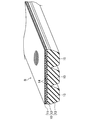
図1は、実施形態に係る方法により製造するVリブドベルトB(伝動ベルト)を示す。このVリブドベルトBは、例えば自動車のエンジンルーム内に設けられる補機駆動ベルト伝動装置等に用いられるエンドレスの動力伝達部材である。VリブドベルトBは、例えば、ベルト長さが700mm以上3000mm以下、ベルト幅が10mm以上36mm以下、及びベルト厚さが4.0mm以上5.0mm以下である。
(V-ribbed belt B)
FIG. 1 shows a V-ribbed belt B (power transmission belt) manufactured by the method according to the embodiment. The V-ribbed belt B is an endless power transmission member used for an accessory drive belt transmission device provided in an engine room of an automobile, for example. The V-ribbed belt B has, for example, a belt length of 700 mm to 3000 mm, a belt width of 10 mm to 36 mm, and a belt thickness of 4.0 mm to 5.0 mm.

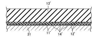
VリブドベルトBは、ベルト外周側の背面ゴム層11と中間の接着ゴム層12とベルト内周側の圧縮ゴム層13との三重層に構成されたベルト本体10を備えている。ベルト本体10の接着ゴム層12の厚さ方向の中間部には、ベルト幅方向にピッチを有する螺旋を形成するように配された心線14が埋設されている。   The V-ribbed belt B includes a belt main body 10 configured as a triple layer of a back rubber layer 11 on the belt outer peripheral side, an intermediate adhesive rubber layer 12 and a compression rubber layer 13 on the belt inner peripheral side. A core wire 14 is embedded in an intermediate portion in the thickness direction of the adhesive rubber layer 12 of the belt body 10 so as to form a spiral having a pitch in the belt width direction.

背面ゴム層11は、断面横長矩形の帯状に形成されている。背面ゴム層11の表面、つまり、ベルト背面は、織布の凹凸面が転写された形態を有する。このベルト背面の凹凸面では、後述する方法でVリブドベルトBを製造することから、織布の単位組織に対応して、凹凸面を構成する凸部の総面積が凹部の総面積よりも広いものとなっている。ベルト背面は、ベルト走行時における騒音を抑制する観点から、経糸及び緯糸の交差角度が90°よりも大きい広角と90°よりも小さい挟角とを有する織布が、それらのうちの広角がベルト長さ方向に開口するように配置されたのと同様の形態を有することが好ましい。この広角は例えば120°である。背面ゴム層11の厚さは例えば0.4mm以上0.8mm以下である。   The back rubber layer 11 is formed in a strip shape having a horizontally long cross section. The surface of the back rubber layer 11, that is, the back surface of the belt has a form in which the uneven surface of the woven fabric is transferred. Since the V-ribbed belt B is manufactured by the method described later on the uneven surface on the back surface of the belt, the total area of the convex portions constituting the uneven surface is wider than the total area of the concave portions corresponding to the unit structure of the woven fabric. It has become. From the viewpoint of suppressing noise when the belt is running, the belt back surface is a woven fabric having a wide angle where warp and weft crossing angles are larger than 90 ° and a narrow angle smaller than 90 °. It is preferable to have the same form as that arranged so as to open in the length direction. This wide angle is, for example, 120 °. The thickness of the back rubber layer 11 is, for example, not less than 0.4 mm and not more than 0.8 mm.

接着ゴム層12も、断面横長矩形の帯状に形成されている。接着ゴム層12の厚さは例えば1.0mm以上2.5mm以下である。   The adhesive rubber layer 12 is also formed in a band shape having a horizontally long cross section. The thickness of the adhesive rubber layer 12 is, for example, not less than 1.0 mm and not more than 2.5 mm.

圧縮ゴム層13は、複数のVリブ15がベルト内周側に垂下するように設けられている。複数のVリブ15は、各々がベルト長さ方向に延びる断面略逆三角形の突条に形成されていると共に、ベルト幅方向に並設されている。圧縮ゴム層13の最大厚さは例えば1.0mm以上3.6mm以下である。各Vリブ15は、例えば、リブ高さが2.0mm以上3.0mm以下、基端間の幅が1.0mm以上3.6mm以下である。Vリブ15の数は例えば3個以上6個以下である(図1では3個)。   The compression rubber layer 13 is provided such that a plurality of V ribs 15 hang down to the belt inner peripheral side. The plurality of V ribs 15 are each formed in a ridge having a substantially inverted triangular cross section extending in the belt length direction, and arranged in parallel in the belt width direction. The maximum thickness of the compressed rubber layer 13 is, for example, not less than 1.0 mm and not more than 3.6 mm. Each V-rib 15 has, for example, a rib height of 2.0 mm to 3.0 mm and a width between proximal ends of 1.0 mm to 3.6 mm. The number of V ribs 15 is, for example, 3 or more and 6 or less (3 in FIG. 1).

背面ゴム層11、接着ゴム層12、及び圧縮ゴム層13は、ゴム成分に種々のゴム配合剤が配合されて混練された未架橋ゴム組成物が加熱及び加圧されてゴム成分が架橋したゴム組成物で形成されている。背面ゴム層11、接着ゴム層12、及び圧縮ゴム層13は、同じ配合のゴム組成物で形成されていても、また、別配合のゴム組成物で形成されていても、どちらでもよい。   The back rubber layer 11, the adhesive rubber layer 12, and the compressed rubber layer 13 are rubbers in which a rubber component is crosslinked by heating and pressurizing an uncrosslinked rubber composition in which various rubber compounding agents are blended in a rubber component. It is formed with a composition. The back rubber layer 11, the adhesive rubber layer 12, and the compressed rubber layer 13 may be formed of the same rubber composition or may be formed of a different rubber composition.

背面ゴム層11、接着ゴム層12、及び圧縮ゴム層13を形成するゴム組成物のゴム成分としては、例えば、エチレン−プロピレン−ジエンターポリマー(EPDM)、エチレン−プロピレンコポリマー(EPM)、エチレン−ブテンコポリマー(EDM)、エチレン−オクテンコポリマー(EOM)などのエチレン−α−オレフィンエラストマー;クロロプレンゴム(CR);クロロスルホン化ポリエチレンゴム(CSM);水素化ニトリルゴム(H−NBR)等が挙げられる。ゴム配合剤としては、カーボンブラックなどの補強材、充填材、可塑剤、加工助剤、加硫助剤、架橋剤、共架橋剤、老化防止剤等が挙げられる。   Examples of the rubber component of the rubber composition forming the back rubber layer 11, the adhesive rubber layer 12, and the compressed rubber layer 13 include ethylene-propylene-diene terpolymer (EPDM), ethylene-propylene copolymer (EPM), ethylene- Examples include ethylene-α-olefin elastomers such as butene copolymer (EDM) and ethylene-octene copolymer (EOM); chloroprene rubber (CR); chlorosulfonated polyethylene rubber (CSM); hydrogenated nitrile rubber (H-NBR). . Examples of rubber compounding agents include reinforcing materials such as carbon black, fillers, plasticizers, processing aids, vulcanization aids, crosslinking agents, co-crosslinking agents, and anti-aging agents.

心線14は、ポリエステル繊維(PET)、ポリエチレンナフタレート繊維(PEN)、アラミド繊維、ビニロン繊維等の撚糸で構成されている。心線14の直径は例えば0.50mm以上2.5mm以下であり、断面における相互に隣接する心線14の中心間の寸法は例えば0.050mm以上0.20mm以下である。心線14は、ベルト本体10の接着ゴム層12に対する接着性を付与するために、成形前にRFL水溶液に浸漬した後に加熱する接着処理及び/又はゴム糊に浸漬した後に乾燥させる接着処理が施されている。   The core wire 14 is composed of twisted yarn such as polyester fiber (PET), polyethylene naphthalate fiber (PEN), aramid fiber, vinylon fiber or the like. The diameter of the core wire 14 is, for example, 0.50 mm or more and 2.5 mm or less, and the dimension between the centers of the adjacent core wires 14 in the cross section is, for example, 0.050 mm or more and 0.20 mm or less. The core wire 14 is subjected to an adhesive treatment that is heated after being immersed in an RFL aqueous solution before molding and / or an adhesive treatment that is dried after being immersed in rubber paste in order to impart adhesion to the adhesive rubber layer 12 of the belt body 10. Has been.

図2は、VリブドベルトBを用いた自動車の補機駆動ベルト伝動装置20のプーリレイアウトを示す。この補機駆動ベルト伝動装置20は、VリブドベルトBが4つのリブプーリ及び2つの平プーリの6つのプーリに巻き掛けられて動力を伝達するサーペンタインドライブ方式のものである。   FIG. 2 shows a pulley layout of an auxiliary drive belt transmission device 20 for an automobile using a V-ribbed belt B. The accessory drive belt transmission device 20 is of a serpentine drive type in which a V-ribbed belt B is wound around six pulleys of four rib pulleys and two flat pulleys to transmit power.

この補機駆動ベルト伝動装置20は、最上位置にリブプーリのパワーステアリングプーリ21が設けられ、そのパワーステアリングプーリ21の下方にリブプーリのACジェネレータプーリ22が設けられている。また、パワーステアリングプーリ21の左下方には平プーリのテンショナプーリ23が設けられており、そのテンショナプーリ23の下方には平プーリのウォーターポンププーリ24が設けられている。更に、テンショナプーリ23の左下方にはリブプーリのクランクシャフトプーリ25が設けられており、そのクランクシャフトプーリ25の右下方にリブプーリのエアコンプーリ26が設けられている。これらのプーリは、例えば、金属のプレス加工品や鋳物、ナイロン樹脂、フェノール樹脂などの樹脂成形品で構成されており、また、プーリ径が例えばφ50mm以上φ150mm以下である。   The auxiliary drive belt transmission device 20 is provided with a power steering pulley 21 of a rib pulley at the uppermost position, and an AC generator pulley 22 of a rib pulley is provided below the power steering pulley 21. A flat pulley tensioner pulley 23 is provided at the lower left of the power steering pulley 21, and a flat pulley water pump pulley 24 is provided below the tensioner pulley 23. Further, a rib pulley crankshaft pulley 25 is provided on the lower left side of the tensioner pulley 23, and a rib pulley air conditioner pulley 26 is provided on the lower right side of the crankshaft pulley 25. These pulleys are made of, for example, a metal stamped product, a cast, a resin molded product such as a nylon resin, a phenol resin, and the pulley diameter is, for example, φ50 mm or more and φ150 mm or less.

この補機駆動ベルト伝動装置20では、VリブドベルトBは、Vリブ15側が接触するようにパワーステアリングプーリ21に巻き掛けられ、次いで、ベルト背面側が接触するようにテンショナプーリ23に巻き掛けられた後、Vリブ15側が接触するようにクランクシャフトプーリ25及びエアコンプーリ26に順に巻き掛けられ、更に、ベルト背面側が接触するようにウォーターポンププーリ24に巻き掛けられ、そして、Vリブ15側が接触するようにACジェネレータプーリ22に巻き掛けられ、最後にパワーステアリングプーリ21に戻るように設けられている。従って、平プーリのテンショナプーリ23及びウォーターポンププーリ24に接触するベルト背面が平プーリ接触面を構成する。プーリ間で掛け渡されるVリブドベルトBの長さであるベルトスパン長は例えば50mm以上300mm以下である。プーリ間で生じ得るミスアライメントは例えば0°以上2°以下である。   In this accessory drive belt transmission 20, after the V-ribbed belt B is wound around the power steering pulley 21 so that the V-rib 15 side comes into contact, and then around the tensioner pulley 23 so that the back side of the belt comes into contact. Further, the crankshaft pulley 25 and the air conditioner pulley 26 are wound in order so that the V rib 15 side contacts, and further, the water pump pulley 24 is wound so that the back side of the belt contacts, and the V rib 15 side contacts. Is wound around the AC generator pulley 22 and finally returned to the power steering pulley 21. Therefore, the back surface of the belt contacting the tension pulley 23 and the water pump pulley 24 of the flat pulley constitutes a flat pulley contact surface. The belt span length, which is the length of the V-ribbed belt B spanned between the pulleys, is, for example, not less than 50 mm and not more than 300 mm. Misalignment that may occur between the pulleys is, for example, 0 ° or more and 2 ° or less.

(VリブドベルトBの製造方法)
実施形態に係るVリブドベルトBの製造方法を、図3A〜8Bに基づいて説明する。実施形態に係るVリブドベルトBの製造方法は、部材準備工程、成形工程、架橋工程、及び仕上工程で構成される。
(Manufacturing method of V-ribbed belt B)
A method for manufacturing the V-ribbed belt B according to the embodiment will be described with reference to FIGS. The manufacturing method of the V-ribbed belt B according to the embodiment includes a member preparation process, a molding process, a crosslinking process, and a finishing process.

<部材準備工程>
部材準備工程では、背面ゴム層11となる背面ゴムシート11’、接着ゴム層12となる接着ゴムシート12’、及び圧縮ゴム層13となる圧縮ゴムシート13’、並びに心線14となる撚糸14’を作製する。
<Component preparation process>
In the member preparation step, the back rubber sheet 11 ′ to be the back rubber layer 11, the adhesive rubber sheet 12 ′ to be the adhesive rubber layer 12, the compressed rubber sheet 13 ′ to be the compression rubber layer 13, and the twisted yarn 14 to be the core wire 14. 'Create.

−背面ゴムシート11’、接着ゴムシート12’、及び圧縮ゴムシート13’−
ニーダー、バンバリーミキサー等の混練機を用い、ゴム成分とゴム配合剤とを混練した後、得られた未架橋ゴム組成物をカレンダー成形等によってシート状に成形して未架橋の背面ゴムシート11’、接着ゴムシート12’、及び圧縮ゴムシート13’を作製する。
-Back rubber sheet 11 ', adhesive rubber sheet 12', and compressed rubber sheet 13 '-
After kneading the rubber component and the rubber compounding agent using a kneader such as a kneader or a Banbury mixer, the resulting uncrosslinked rubber composition is formed into a sheet by calendering or the like to form an uncrosslinked back rubber sheet 11 ′. Then, an adhesive rubber sheet 12 ′ and a compressed rubber sheet 13 ′ are produced.

−撚糸14’−
心線14を構成する撚糸14’に、RFL水溶液に浸漬して加熱する接着処理、及び/又は、ゴム糊に浸漬して乾燥させる接着処理を施す。これらの接着処理の前に、エポキシ樹脂溶液又はイソシアネート樹脂溶液に浸漬して加熱する下地処理を施してもよい。
-Twisted yarn 14'-
The twisted yarn 14 ′ constituting the core wire 14 is subjected to an adhesion treatment in which it is immersed in an RFL aqueous solution and heated and / or an adhesion treatment in which it is immersed in rubber glue and dried. Prior to these adhesion treatments, a ground treatment may be performed by dipping in an epoxy resin solution or an isocyanate resin solution and heating.

<成形工程>
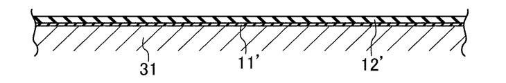
成形工程では、まず、成形機(不図示)に、軸方向が水平方向となるように円筒状の成形マンドレル31を回転可能に軸支し、図3Aに示すように、成形マンドレル31上に背面ゴムシート11’を巻き付け、その上に更に接着ゴムシート12’を巻き付ける。成形マンドレル31は、製造するVリブドベルトBのベルト長さに対応したものを選択する。これにより、背面ゴムシート11’上に接着ゴムシート12’を積層する。なお、所定長の背面ゴムシート11’の両端を接合して筒状に形成したものを作製し、それを成形マンドレル31上に被せてもよい。また、背面ゴムシート11’と接着ゴムシート12’とを積層一体化させたものを作製し、それを成形マンドレル31上に巻き付けてもよく、或いは、その積層体の所定長を、接着ゴムシート12’が外側となるように両端を接合して筒状に形成したものを作製し、それを成形マンドレル31に被せてもよい。
<Molding process>
In the molding process, first, a cylindrical molding mandrel 31 is rotatably supported on a molding machine (not shown) so that the axial direction is horizontal, and the rear surface is placed on the molding mandrel 31 as shown in FIG. 3A. A rubber sheet 11 'is wound, and an adhesive rubber sheet 12' is further wound thereon. The molding mandrel 31 is selected corresponding to the belt length of the V-ribbed belt B to be manufactured. Thereby, the adhesive rubber sheet 12 ′ is laminated on the back rubber sheet 11 ′. In addition, what formed the cylindrical shape which joined the both ends of back rubber sheet 11 'of predetermined length may be produced, and it may cover on the shaping | molding mandrel 31. FIG. Alternatively, the back rubber sheet 11 ′ and the adhesive rubber sheet 12 ′ may be laminated and integrated and wound around the molding mandrel 31, or the predetermined length of the laminate may be bonded to the adhesive rubber sheet. Alternatively, both ends may be joined so that 12 ′ is on the outside and formed into a cylindrical shape, which may be covered with the molding mandrel 31.

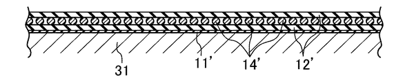
次いで、図3Bに示すように、接着ゴムシート12’上に撚糸14’を螺旋状に巻き付け、その上に更に接着ゴムシート12’を巻き付ける。これにより、接着ゴムシート12’上に撚糸14’の層を積層し、また、撚糸14’の層上に接着ゴムシート12’を積層する。   Next, as shown in FIG. 3B, the twisted yarn 14 'is spirally wound on the adhesive rubber sheet 12', and the adhesive rubber sheet 12 'is further wound thereon. Thereby, the layer of the twisted yarn 14 'is laminated on the adhesive rubber sheet 12', and the adhesive rubber sheet 12 'is laminated on the layer of the twisted yarn 14'.

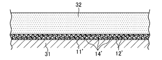
次いで、図3Cに示すように、全周に渡って接着ゴムシート12’の上からローラー32で押圧する。これにより、撚糸14’の間にゴムを流動させて撚糸14’を一対の接着ゴムシート12’間に埋設させると共に位置固定して全体として一体化した筒状体を形成する。なお、この操作は、撚糸14’の層上に接着ゴムシート12’を巻き付けるのと同時に行ってもよい。   Next, as shown in FIG. 3C, the roller 32 is pressed from above the adhesive rubber sheet 12 'over the entire circumference. As a result, the rubber is caused to flow between the twisted yarns 14 ′ so that the twisted yarns 14 ′ are embedded between the pair of adhesive rubber sheets 12 ′ and are fixed in position to form an integrated cylindrical body. This operation may be performed simultaneously with winding the adhesive rubber sheet 12 'on the layer of the twisted yarn 14'.

続いて、図3Dに示すように、筒状体の接着ゴムシート12’上に圧縮ゴムシート13’を複数層巻き付ける。なお、所定長の厚肉の圧縮ゴムシート13’の両端を接合して筒状に形成したものを作製し、それを接着ゴムシート12’上に被せてもよい。   Subsequently, as shown in FIG. 3D, a plurality of layers of compressed rubber sheets 13 ′ are wound around the adhesive rubber sheet 12 ′ having a cylindrical shape. It should be noted that a thick compressed rubber sheet 13 ′ having a predetermined length may be joined at both ends to form a cylindrical shape, which may be covered on the adhesive rubber sheet 12 ′.

以上のようにして、成形マンドレル31上に、背面ゴムシート11’、接着ゴムシート12’、撚糸14’、接着ゴムシート12’、及び圧縮ゴムシート13’が内側から順に積層された円筒状の未架橋スラブS’を成形する。   As described above, a cylindrical shape in which the back rubber sheet 11 ′, the adhesive rubber sheet 12 ′, the twisted yarn 14 ′, the adhesive rubber sheet 12 ′, and the compressed rubber sheet 13 ′ are laminated in order from the inside on the molding mandrel 31. An uncrosslinked slab S ′ is formed.

<架橋工程>
図4A及びBは、架橋工程において用いるベルト成型装置40を示す。
<Crosslinking process>
4A and 4B show a belt molding apparatus 40 used in the crosslinking process.

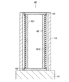
ベルト成型装置40は、基台41と、その上に立設された円柱状の膨張ドラム42と、その外側に設けられた円筒状の円筒金型43とを備える。   The belt molding apparatus 40 includes a base 41, a columnar expansion drum 42 erected on the base 41, and a cylindrical cylindrical mold 43 provided on the outside thereof.

膨張ドラム42は、中空円柱状に形成されたドラム本体421と、その外周に外嵌めされた円筒状の膨張スリーブ422とを有する。ドラム本体421の外周部には、各々、内部に連通した多数の通気孔423が形成されている。膨張スリーブ422の両端部は、それぞれドラム本体421との間で固定リング44,45によって封止されている。また、ベルト成型装置40には、ドラム本体421の内部に高圧空気を導入して加圧する加圧手段(不図示)が設けられており、この加圧手段によりドラム本体421の内部に高圧空気が導入されると、高圧空気が通気孔423を通ってドラム本体421と膨張スリーブ422との間に入って膨張スリーブ422を径方向外向きに膨張させるように構成されている。   The expansion drum 42 includes a drum main body 421 formed in a hollow cylindrical shape, and a cylindrical expansion sleeve 422 that is externally fitted on the outer periphery thereof. A large number of vent holes 423 communicating with the inside are formed in the outer peripheral portion of the drum main body 421. Both end portions of the expansion sleeve 422 are sealed with fixing rings 44 and 45 between the drum body 421 and the both ends. Further, the belt molding apparatus 40 is provided with a pressurizing means (not shown) that introduces and pressurizes high-pressure air into the drum main body 421, and the high-pressure air is introduced into the drum main body 421 by the pressurizing means. When introduced, the high-pressure air is configured to enter the space between the drum body 421 and the expansion sleeve 422 through the vent hole 423 and expand the expansion sleeve 422 radially outward.

膨張スリーブ422は、内周側のゴム製のスリーブ本体422aとその外周面に貼設された織布422bとを有する。   The expansion sleeve 422 includes a rubber sleeve main body 422a on the inner peripheral side and a woven fabric 422b attached to the outer peripheral surface thereof.

スリーブ本体422aは、ゴム成分に種々のゴム配合剤が配合されて混練された未架橋ゴム組成物が加熱及び加圧されてゴム成分が架橋したゴム組成物で形成されている。ゴム成分としては、例えば、天然ゴム(NR)、イソプレンゴム(IR)、ブタジエンゴム(BR)、スチレンブタジエンゴム(SBR)、クロロプレンゴム(CR)、アクリロニトリルブタジエンゴム(NBR)、水素化ニトリルゴム(H−NBR)、ブチルゴム(IIR)、クロロスルホン化ポリエチレンゴム(CSM)、エチレンプロピレンゴム、エチレン−プロピレン−ジエンターポリマー(EPDM)やエチレン−プロピレンコポリマー(EPM)などのエチレン−α−オレフィンエラストマー等が挙げられる。ゴム配合剤としては、カーボンブラックなどの補強材、充填材、可塑剤、加工助剤、加硫助剤、架橋剤、共架橋剤、老化防止剤等が挙げられる。   The sleeve main body 422a is formed of a rubber composition in which a rubber component is crosslinked by heating and pressurizing an uncrosslinked rubber composition in which various rubber compounding agents are blended with a rubber component. Examples of the rubber component include natural rubber (NR), isoprene rubber (IR), butadiene rubber (BR), styrene butadiene rubber (SBR), chloroprene rubber (CR), acrylonitrile butadiene rubber (NBR), hydrogenated nitrile rubber ( H-NBR), butyl rubber (IIR), chlorosulfonated polyethylene rubber (CSM), ethylene propylene rubber, ethylene-α-olefin elastomer such as ethylene-propylene-diene terpolymer (EPDM) and ethylene-propylene copolymer (EPM), etc. Is mentioned. Examples of rubber compounding agents include reinforcing materials such as carbon black, fillers, plasticizers, processing aids, vulcanization aids, crosslinking agents, co-crosslinking agents, and anti-aging agents.

図5A及びBは織布422bの一例を示す。   5A and 5B show an example of a woven fabric 422b.

織布422bを形成する繊維材料としては、例えば、綿、麻等の天然繊維、ナイロン66やナイロン46やナイロン6などの脂肪族ポリアミド繊維、ポリエステル繊維、アラミド繊維、PBO繊維等の化学繊維が挙げられる。織布422bは、これらのうちの1種又は2種以上の繊維材料で形成されていることが好ましい。   Examples of the fiber material forming the woven fabric 422b include natural fibers such as cotton and hemp, aliphatic polyamide fibers such as nylon 66, nylon 46, and nylon 6, polyester fibers, aramid fibers, and chemical fibers such as PBO fibers. It is done. The woven fabric 422b is preferably formed of one or more of these fiber materials.

織布422bは、外向きに露出した外周面が経糸Wa及び緯糸Weの交錯により形成された凹凸面であり、この凹凸面がベルト背面に転写される成型面を構成する。そして、この成型面である織布422bの凹凸面は、織布422bの単位組織において、凹凸面を構成する凹部の総面積が凸部の総面積よりも広い。織布422bの単位組織において、凹凸面を構成する凹部の総面積は、好ましくは50%以上80%以下、より好ましくは60%以上70%以下である。   In the woven fabric 422b, the outer peripheral surface exposed outward is an uneven surface formed by the intersection of the warp yarn Wa and the weft yarn We, and this uneven surface constitutes a molding surface to be transferred to the belt back surface. And the uneven | corrugated surface of the woven fabric 422b which is this shaping | molding surface has a larger total area of the recessed part which comprises an uneven surface in the unit structure | tissue of the woven fabric 422b than the total area of a convex part. In the unit structure of the woven fabric 422b, the total area of the recesses constituting the uneven surface is preferably 50% to 80%, more preferably 60% to 70%.

このような織布422bの構成は、織布422bを形成する経糸Wa及び緯糸Weのうちいずれか一方が他方よりも繊度が大きいことにより容易に得ることができる。つまり、図5Aを例として説明すると、繊度が大きい方の相対的に太い緯糸Weが嵩高いことにより、相対的に細い経糸Waがその嵩高い相対的に太い緯糸Weと交差して小さな凸部を離散的に形成する一方、それ以外の部分が相対的に太い緯糸Weが露出した凹部で占められ、その結果形成される凹凸面において、それを構成する凹部の総面積が凸部の総面積よりも広くなる。そのため、製造されるVリブドベルトBのベルト背面には、図6に示すように、織布422bの凹凸面の凸部に対応した平面視が略楕円又は略長方形の細長形状の凹孔16が、その長軸方向に一定間隔をおいて直列に並ぶと共に、長軸方向と角度をなす方向に平行に並ぶように配設された形態を得ることができる。   Such a configuration of the woven fabric 422b can be easily obtained because one of the warp yarn Wa and the weft yarn We forming the woven fabric 422b is finer than the other. That is, when FIG. 5A is described as an example, a relatively thick warp Wa intersects the bulky relatively thick weft We because the relatively thick weft We of the larger fineness is bulky, and a small convex portion Are formed discretely, while the other portions are occupied by the recessed portions where the relatively thick wefts Wee are exposed, and in the uneven surface formed as a result, the total area of the recessed portions constituting the surface is the total area of the protruding portions Wider than. Therefore, on the belt rear surface of the V-ribbed belt B to be manufactured, as shown in FIG. 6, the elongated concave hole 16 having a substantially elliptical or substantially rectangular shape in plan view corresponding to the convex portion of the concave and convex surface of the woven fabric 422b, It is possible to obtain a configuration in which the long axis direction is arranged in series at a constant interval and is arranged in parallel to a direction that forms an angle with the long axis direction.

織布422bの組織は、特に限定されるものではないが、平織又は変化平織であることが好ましい。変化平織としては、例えば、畦織(畝織)、斜子織等が挙げられる。織布422bの組織は、図5A及びBに示すような変化平織である畦織であることがより好ましい。   The structure of the woven fabric 422b is not particularly limited, but is preferably a plain weave or a changed plain weave. Examples of the changed plain weave include cocoon weave (cone weave) and skew weave. The structure of the woven fabric 422b is more preferably a knit weave which is a plain change weave as shown in FIGS. 5A and 5B.

実施形態に係るVリブドベルトBの製造方法によれば、このように平プーリ接触面を構成するベルト背面の成型に用いる膨張スリーブ422の織布422bの単位組織において、成型面である織布422bの凹凸面を構成する凹部の総面積が凸部の総面積よりも広く、従って、それが転写されるベルト背面の凹凸面では、織布422bの単位組織に対応する部分において、平プーリのテンショナプーリ23及びウォーターポンププーリ24に直接接触する凸部の総面積が凹部の総面積よりも広くなるので、それらの平プーリのテンショナプーリ23及びウォーターポンププーリ24の接触圧力が低く抑えられ、その結果、ベルト背面の優れた耐摩耗性を得ることができる。   According to the manufacturing method of the V-ribbed belt B according to the embodiment, in the unit structure of the woven fabric 422b of the expansion sleeve 422 used for molding the back surface of the belt constituting the flat pulley contact surface, the woven fabric 422b which is the molding surface is formed. The total area of the concave portions constituting the concave / convex surface is larger than the total area of the convex portions. Therefore, in the concave / convex surface on the back surface of the belt to which it is transferred, the flat pulley tensioner pulley is in the portion corresponding to the unit structure of the woven fabric 422b. 23 and the total area of the convex portions that are in direct contact with the water pump pulley 24 are larger than the total area of the concave portions, so that the contact pressure between the tensioner pulley 23 and the water pump pulley 24 of those flat pulleys can be kept low. Excellent wear resistance on the back of the belt can be obtained.

また、ベルト走行時における騒音を抑制する観点からは、後述するように成型面である織布422bの凹凸面に未架橋ゴム組成物を圧接させるとき、織布422bを、織布422bを形成する経糸Wa及び緯糸Weのそれぞれの延びる方向がベルト長さ方向及びベルト幅方向のいずれに対応する方向に対しても角度を有するように配置することが好ましい。従って、織布422bは、膨張ドラム42に、経糸Wa及び緯糸Weのそれぞれの延びる方向が膨張ドラム42の周方向及び軸方向のいずれの方向に対しても角度を有するように設けられていることが好ましい。このようにすれば、製造されるVリブドベルトBのベルト背面には、経糸Wa及び緯糸Weのそれぞれの延びる方向がベルト長さ方向及びベルト幅方向のいずれにも角度を有するように織布422bが設けられたのと同様の形態を得ることができる。   Further, from the viewpoint of suppressing noise during belt running, when the uncrosslinked rubber composition is pressed against the uneven surface of the woven fabric 422b which is a molding surface, the woven fabric 422b is formed as described later. It is preferable to arrange the warp yarn Wa and the weft yarn We so that each extending direction has an angle with respect to the direction corresponding to either the belt length direction or the belt width direction. Accordingly, the woven fabric 422b is provided on the expansion drum 42 such that the extending directions of the warp yarn Wa and the weft yarn We have an angle with respect to both the circumferential direction and the axial direction of the expansion drum 42. Is preferred. In this way, the woven fabric 422b is provided on the back surface of the manufactured V-ribbed belt B so that the extending directions of the warp yarn Wa and the weft yarn We have angles in both the belt length direction and the belt width direction. A form similar to that provided can be obtained.

この場合、耐屈曲疲労性を高める観点からは、成型面である織布422bの凹凸面に未架橋ゴム組成物を圧接させるとき、織布422bを形成する経糸Wa及び緯糸Weのベルト長さ方向に対応する方向に開口した交差角度が90°よりも大きい広角θであることが好ましい。従って、織布422bは、経糸Wa及び緯糸Weの交差角度が90°よりも大きい広角θと90°よりも小さい挟角とを有し、膨張ドラム42に、経糸Wa及び緯糸Weの膨張ドラム42の周方向に開口した交差角度が広角θとなるように設けられていることが好ましい。このようにすれば、製造されるVリブドベルトBのベルト背面には、経糸Wa及び緯糸Weのベルト長さ方向に対応する方向に開口した交差角度が90°よりも大きい広角θであるように織布422bが設けられたのと同様の形態を得ることができる。なお、膨張スリーブ422が膨張すると織布422bの広角θは狭くなるので、膨張前の膨張スリーブ422における織布422bの広角θは、ベルト背面の広角よりも広く設定することが好ましい。例えば、ベルト背面の広角を120°とする場合、織布422bの広角θを約130°に設定することが好ましい。なお、経糸Wa及び緯糸Weの交差角度が広角θ及び挟角を有する織布422bは、例えば、国際公開96/22479等に開示された方法で作製することができる。   In this case, from the viewpoint of increasing the bending fatigue resistance, when the uncrosslinked rubber composition is pressed against the uneven surface of the woven fabric 422b which is a molding surface, the warp Wa and the weft Wet forming the woven fabric 422b are in the belt length direction. It is preferable that the crossing angle opened in the direction corresponding to is a wide angle θ larger than 90 °. Therefore, the woven fabric 422b has a wide angle θ where the intersecting angle of the warp Wa and the weft Wet is larger than 90 ° and a narrow angle smaller than 90 °, and the expansion drum 42 has the expansion drum 42 for the warp Wa and the weft Wen. It is preferable that the crossing angle opened in the circumferential direction is a wide angle θ. In this way, the back surface of the manufactured V-ribbed belt B is woven so that the crossing angle opened in the direction corresponding to the belt length direction of the warp yarn Wa and the weft yarn We is a wide angle θ larger than 90 °. A form similar to that provided with the cloth 422b can be obtained. When the expansion sleeve 422 is expanded, the wide angle θ of the woven fabric 422b is narrowed. Therefore, the wide angle θ of the woven fabric 422b in the expansion sleeve 422 before expansion is preferably set wider than the wide angle of the back surface of the belt. For example, when the wide angle on the back surface of the belt is 120 °, it is preferable to set the wide angle θ of the woven fabric 422b to about 130 °. In addition, the woven fabric 422b in which the intersecting angle between the warp yarn Wa and the weft yarn We has the wide angle θ and the included angle can be manufactured by a method disclosed in, for example, International Publication 96/22479.

以上の構成の膨張スリーブ422は以下のようにして作製することができる。   The expansion sleeve 422 having the above-described configuration can be manufactured as follows.

まず、ニーダー、バンバリーミキサー等の混練機を用い、ゴム成分とゴム配合剤とを混練した後、得られた未架橋ゴム組成物をカレンダー成形等によってシート状に成形して長尺の未架橋ゴムシート422a’を作製する。また、長尺の織布422b’に接着処理を施す。接着処理は、織布422b’をRFL水溶液に浸漬して加熱する接着処理、ゴム糊に浸漬して乾燥させる接着処理、及び接着面にゴム糊をコーティングする接着処理である。   First, after kneading a rubber component and a rubber compounding agent using a kneader such as a kneader or a Banbury mixer, the resulting uncrosslinked rubber composition is formed into a sheet shape by calendar molding or the like to form a long uncrosslinked rubber A sheet 422a ′ is produced. Further, the long woven fabric 422b 'is subjected to an adhesion treatment. The adhesion treatment is an adhesion treatment in which the woven fabric 422b 'is immersed in an RFL aqueous solution and heated, an adhesion treatment in which the woven fabric 422b' is immersed in rubber glue and dried, and an adhesion treatment in which the adhesive surface is coated with rubber glue.

続いて、図7Aに示すように、未架橋ゴムシート422a’と接着処理を施した織布422b’とを一対のロールR間で連続的に貼り合わせて加熱及び加圧することにより、未架橋ゴムシート422a’を架橋させると共に織布422b’と一体化させて長尺のゴムシート422a’及び織布422b’の積層体を得る。   Subsequently, as shown in FIG. 7A, the uncrosslinked rubber sheet 422a ′ and the woven fabric 422b ′ subjected to the adhesion treatment are continuously bonded between a pair of rolls R, and heated and pressed to thereby form uncrosslinked rubber. The sheet 422a ′ is cross-linked and integrated with the woven fabric 422b ′ to obtain a laminate of the long rubber sheet 422a ′ and the woven fabric 422b ′.

そして、得られた積層体から所定長さを切り出し、図7B及び7Cに示すように、織布422b’が外側となるようにその両端を接合して円筒状に形成することにより膨張スリーブ422を得る。なお、この接合は、積層体の厚さ方向に沿った端面又は厚さ方向に対して傾斜した端面にいわゆる加硫接着剤を塗布し、両端面を突き合わせ、その部分を一対の熱盤間で挟んで加熱及び加圧して加硫接着剤を架橋させることにより行うことができる。また、膨張スリーブ422の軸方向に対して傾斜する方向に接合部が形成されるように積層体の接合を行ってもよい。   Then, a predetermined length is cut out from the obtained laminate, and as shown in FIGS. 7B and 7C, the both ends of the woven fabric 422b ′ are joined to form the cylindrical shape by joining them at the outer side. obtain. Note that this bonding is performed by applying a so-called vulcanized adhesive to an end face along the thickness direction of the laminate or an end face inclined with respect to the thickness direction, butting both end faces, and the portion is sandwiched between a pair of hot plates. It can be carried out by crosslinking and heating and pressurizing the vulcanized adhesive. In addition, the laminates may be bonded so that the bonding portion is formed in a direction inclined with respect to the axial direction of the expansion sleeve 422.

円筒金型43は基台41に脱着可能に構成されている。基台41に取り付けられた円筒金型43は、膨張ドラム42との間に間隔をおいて同心状に設けられる。円筒金型43は、内周面に、各々、周方向に延びる複数のVリブ形成溝431が軸方向に連設されている。各Vリブ形成溝431は、製造するVリブドベルトBのVリブ15に対応する形状に形成されている。ベルト成型装置40には、円筒金型43の加熱手段及び冷却手段(いずれも不図示)が設けられており、これらの加熱手段及び冷却手段により円筒金型43の温度制御が可能となるように構成されている。   The cylindrical mold 43 is configured to be detachable from the base 41. The cylindrical mold 43 attached to the base 41 is provided concentrically with a space between the expansion drum 42. In the cylindrical mold 43, a plurality of V-rib forming grooves 431 extending in the circumferential direction are connected to the inner circumferential surface in the axial direction. Each V-rib forming groove 431 is formed in a shape corresponding to the V-rib 15 of the V-ribbed belt B to be manufactured. The belt molding apparatus 40 is provided with heating means and cooling means (both not shown) for the cylindrical mold 43 so that the temperature of the cylindrical mold 43 can be controlled by these heating means and cooling means. It is configured.

架橋工程では、成形マンドレル31から未架橋スラブを抜き取り、この未架橋スラブを、ベルト成型装置40における基台41から取り外した円筒金型43の内側に内嵌めするように配置する。円筒金型43は、製造するVリブドベルトBのベルト長さに対応したものを選択する。   In the bridging step, the uncrosslinked slab is extracted from the molding mandrel 31, and the uncrosslinked slab is disposed so as to be fitted inside the cylindrical mold 43 removed from the base 41 in the belt molding apparatus 40. The cylindrical mold 43 corresponding to the belt length of the V-ribbed belt B to be manufactured is selected.

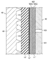
次いで、図8Aに示すように、未架橋スラブS’を設けた円筒金型43を、膨張ドラム42を覆うように配置して基台41に取り付ける。このとき、円筒金型43に設けた未架橋スラブS’と膨張ドラム42との間には隙間が形成される。   Next, as shown in FIG. 8A, the cylindrical mold 43 provided with the uncrosslinked slab S ′ is disposed so as to cover the expansion drum 42 and attached to the base 41. At this time, a gap is formed between the uncrosslinked slab S ′ provided in the cylindrical mold 43 and the expansion drum 42.

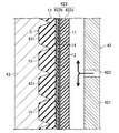
そして、図8Bに示すように、加熱手段により円筒金型43を昇温させると共に、加圧手段により膨張ドラム42のドラム本体421の内部に高圧空気を導入して膨張スリーブ422を径方向外向きに膨張させ、その状態を所定時間保持する。これにより、円筒金型43と膨張スリーブ422との間で未架橋スラブS’を圧縮し、圧縮ゴムシート13’をVリブ形成溝431に流入させてVリブ15を形成し、また、背面ゴムシート11’、接着ゴムシート12’、及び圧縮ゴムシート13’のゴム成分を架橋させて一体化させると共に撚糸14’と複合化させ、最終的に、円筒状のベルトスラブSを成型する。更に、膨張スリーブ422の外周に設けられた織布422bの凹凸面を成型面として、その成型面に未架橋スラブの内周面を構成する背面ゴムシート11’の未架橋ゴム組成物を圧接させて織布422bの凹凸面を転写すると共に未架橋ゴム組成物を架橋させる。そのため、このベルトスラブSの内周面には織布422bの凹凸面が転写され、それがVリブドベルトBの平プーリ接触面を構成するベルト背面となる。このときの加熱温度は例えば100〜180℃、圧力は例えば0.5〜2.0MPa、及び加工時間は例えば10〜60分である。   Then, as shown in FIG. 8B, the cylindrical mold 43 is heated by the heating means, and high-pressure air is introduced into the inside of the drum body 421 of the expansion drum 42 by the pressurizing means so that the expansion sleeve 422 is directed outward in the radial direction. And the state is maintained for a predetermined time. As a result, the uncrosslinked slab S ′ is compressed between the cylindrical mold 43 and the expansion sleeve 422, the compressed rubber sheet 13 ′ is caused to flow into the V rib forming groove 431, and the V rib 15 is formed. The rubber components of the sheet 11 ′, the adhesive rubber sheet 12 ′, and the compressed rubber sheet 13 ′ are cross-linked and integrated, and combined with the twisted yarn 14 ′. Finally, the cylindrical belt slab S is molded. Further, the uneven surface of the woven fabric 422b provided on the outer periphery of the expansion sleeve 422 is used as a molding surface, and the uncrosslinked rubber composition of the back rubber sheet 11 ′ constituting the inner circumferential surface of the uncrosslinked slab is pressed against the molding surface. The uneven surface of the woven fabric 422b is transferred and the uncrosslinked rubber composition is crosslinked. Therefore, the concavo-convex surface of the woven fabric 422b is transferred to the inner peripheral surface of the belt slab S, which becomes the belt back surface constituting the flat pulley contact surface of the V-ribbed belt B. The heating temperature at this time is, for example, 100 to 180 ° C., the pressure is, for example, 0.5 to 2.0 MPa, and the processing time is, for example, 10 to 60 minutes.

<仕上工程>
仕上工程では、加圧手段によるドラム本体421の内部の加圧を解除すると共に、冷却手段により円筒金型43を冷却した後、基台41から円筒金型43を取り外し、円筒金型43から、その内側に成型されたベルトスラブを取り出し、それを所定のVリブ15の数の幅で輪切りし、表裏を裏返すことによりVリブドベルトBを得る。
<Finish process>
In the finishing step, the internal pressure of the drum body 421 by the pressurizing unit is released and the cylindrical mold 43 is cooled by the cooling unit, and then the cylindrical mold 43 is removed from the base 41 and the cylindrical mold 43 is removed. A belt slab molded on the inside is taken out, cut into a predetermined number of V-ribs 15 in width, and turned upside down to obtain a V-ribbed belt B.

本発明は、伝動ベルトの製造方法の技術分野について有用である。   The present invention is useful in the technical field of a method for manufacturing a transmission belt.

B Vリブドベルト(伝動ベルト)
Wa 経糸
We 緯糸
422b 織布
B V-ribbed belt (power transmission belt)
Wa warp yarn Weft 422b woven fabric

Claims (6)

経糸及び緯糸で形成された織布の凹凸面を成型面として、前記成型面に未架橋ゴム組成物を圧接させて前記凹凸面を転写すると共に前記未架橋ゴム組成物を架橋させることによりゴムの平プーリ接触面を成型する伝動ベルトの製造方法であって、
前記成型面である前記織布の前記凹凸面は、前記織布の単位組織において、前記凹凸面を構成する凹部の総面積が凸部の総面積よりも広い伝動ベルトの製造方法。
Using the uneven surface of the woven fabric formed of warp and weft as a molding surface, the uncrosslinked rubber composition is pressed onto the molding surface to transfer the uneven surface, and the uncrosslinked rubber composition is crosslinked to form a rubber. A method of manufacturing a transmission belt for molding a flat pulley contact surface,
The concavo-convex surface of the woven fabric that is the molding surface is a method for manufacturing a transmission belt in which the total area of the concave portions constituting the concavo-convex surface is wider than the total area of the convex portions in the unit structure of the woven fabric.
請求項1に記載された伝動ベルトの製造方法において、
前記織布を形成する前記経糸及び前記緯糸のうちいずれか一方が他方よりも繊度が大きい伝動ベルトの製造方法。
In the manufacturing method of the power transmission belt described in Claim 1,
One of the warp and the weft forming the woven fabric is a method for producing a transmission belt in which either one has a fineness greater than the other.
請求項1又は2に記載された伝動ベルトの製造方法において、
前記織布が平織織布又は変化平織織布である伝動ベルトの製造方法。
In the manufacturing method of the power transmission belt described in Claim 1 or 2,
A method for manufacturing a transmission belt, wherein the woven fabric is a plain woven fabric or a changed plain woven fabric.
請求項3に記載された伝動ベルトの製造方法において、
前記織布が畦織織布である伝動ベルトの製造方法。
In the manufacturing method of the power transmission belt described in Claim 3,
A method for manufacturing a transmission belt, wherein the woven fabric is a woven fabric.
請求項1乃至4のいずれかに記載された伝動ベルトの製造方法において、
前記成型面に未架橋ゴム組成物を圧接させるとき、前記織布を、前記織布を形成する前記経糸及び前記緯糸のそれぞれの延びる方向がベルト長さ方向及びベルト幅方向のいずれに対応する方向に対しても角度を有するように配置する伝動ベルトの製造方法。
In the manufacturing method of the power transmission belt according to any one of claims 1 to 4,
When the uncrosslinked rubber composition is pressed against the molding surface, the woven fabric is a direction in which the extending direction of the warp and the weft forming the woven fabric corresponds to either the belt length direction or the belt width direction. The manufacturing method of the transmission belt arrange | positioned so that it may have an angle with respect to.
請求項5に記載された伝動ベルトの製造方法において、
前記成型面に未架橋ゴム組成物を圧接させるとき、前記織布を形成する前記経糸及び前記緯糸のベルト長さ方向に対応する方向に開口した交差角度が90°よりも大きい伝動ベルトの製造方法。
In the manufacturing method of the power transmission belt according to claim 5,
A method for producing a transmission belt having an intersection angle larger than 90 ° opened in a direction corresponding to a belt length direction of the warp and weft forming the woven fabric when the uncrosslinked rubber composition is pressed against the molding surface .
JP2017135531A 2017-07-11 2017-07-11 Transmission belt manufacturing method Pending JP2019019831A (en)

Priority Applications (1)

Application Number Priority Date Filing Date Title
JP2017135531A JP2019019831A (en) 2017-07-11 2017-07-11 Transmission belt manufacturing method

Applications Claiming Priority (1)

Application Number Priority Date Filing Date Title
JP2017135531A JP2019019831A (en) 2017-07-11 2017-07-11 Transmission belt manufacturing method

Publications (1)

Publication Number Publication Date
JP2019019831A true JP2019019831A (en) 2019-02-07

Family

ID=65355481

Family Applications (1)

Application Number Title Priority Date Filing Date
JP2017135531A Pending JP2019019831A (en) 2017-07-11 2017-07-11 Transmission belt manufacturing method

Country Status (1)

Country Link
JP (1) JP2019019831A (en)

Cited By (1)

* Cited by examiner, † Cited by third party
Publication number Priority date Publication date Assignee Title
DE102019131032A1 (en) * 2019-11-18 2021-05-20 Arntz Beteiligungs Gmbh & Co. Kg Drive belt and method of making a drive belt

Cited By (1)

* Cited by examiner, † Cited by third party
Publication number Priority date Publication date Assignee Title
DE102019131032A1 (en) * 2019-11-18 2021-05-20 Arntz Beteiligungs Gmbh & Co. Kg Drive belt and method of making a drive belt

Similar Documents

Publication Publication Date Title
JP3616373B2 (en) Power transmission belt with bag over cord
KR102062739B1 (en) Transmission belt and manufacturing method therefor
JP6214838B1 (en) Belt manufacturing method, cylindrical mold and bridging device used therefor
JPWO2019069842A1 (en) Transmission belt
KR101933204B1 (en) Belt manufacturing method and two-layer adapter
JP6230756B1 (en) V-ribbed belt manufacturing method
JP6246420B1 (en) V-ribbed belt manufacturing method
JP4214161B2 (en) Transmission belt manufacturing method
JP2022157057A (en) V-ribbed belt
JP2019019831A (en) Transmission belt manufacturing method
WO2017169412A1 (en) Transmission belt manufacturing method
JP6628666B2 (en) Method of manufacturing power transmission belt
JP6007353B2 (en) V-ribbed belt, method for manufacturing the same, and belt transmission device
JP6227842B1 (en) Low edge V belt manufacturing method
JP6230753B1 (en) V-belt manufacturing method
WO2024009663A1 (en) V-ribbed belt and method for manufacturing same
WO2024116725A1 (en) Toothed belt
JP6192876B1 (en) Transmission belt manufacturing method
JP2024078463A (en) Toothed belt
JP2000102988A (en) Production of v-ribbed belt
JP5881409B2 (en) Transmission belt
JPWO2020105286A1 (en) Manufacturing method of transmission belt
JPH03126533A (en) Manufacture of v ribbed belt
JP2000304104A (en) Transmission belt with cog and manufacture thereof
JP2019007596A (en) Friction transmission belt and method for producing the same