US712369A - Fluid-pressure turbine. - Google Patents
Fluid-pressure turbine. Download PDFInfo
- Publication number
- US712369A US712369A US7565001A US1901075650A US712369A US 712369 A US712369 A US 712369A US 7565001 A US7565001 A US 7565001A US 1901075650 A US1901075650 A US 1901075650A US 712369 A US712369 A US 712369A
- Authority
- US
- United States
- Prior art keywords
- blades
- blade
- turbine
- guide
- fixed
- Prior art date
- Legal status (The legal status is an assumption and is not a legal conclusion. Google has not performed a legal analysis and makes no representation as to the accuracy of the status listed.)
- Expired - Lifetime
Links
Images

Classifications
-
- F—MECHANICAL ENGINEERING; LIGHTING; HEATING; WEAPONS; BLASTING
- F01—MACHINES OR ENGINES IN GENERAL; ENGINE PLANTS IN GENERAL; STEAM ENGINES
- F01D—NON-POSITIVE DISPLACEMENT MACHINES OR ENGINES, e.g. STEAM TURBINES
- F01D9/00—Stators
- F01D9/02—Nozzles; Nozzle boxes; Stator blades; Guide conduits, e.g. individual nozzles
- F01D9/04—Nozzles; Nozzle boxes; Stator blades; Guide conduits, e.g. individual nozzles forming ring or sector
- F01D9/042—Nozzles; Nozzle boxes; Stator blades; Guide conduits, e.g. individual nozzles forming ring or sector fixing blades to stators
Definitions
- the blades are so shaped that the several streams of steam issuing from between them unite to form a practically solid parallel annular jet the stream-lines of which are nearly all parallel.
- the passage-way betweeneach pair of blades is made to continually increase in transverse or cross-sectional area from the inlet or from a point near the inlet to the exit, the ratio of this increase being such that the working fluid in its passage will expand fully to the increased volume, corresponding to the diminished pressure before leaving the said passage-way, so that having then little or no further tendency to spread laterally it will issue in a practically parallel jet in a given direction with the full velocity due to the drop in pressure.
- the blades When the ratio of expansion is high and the velocity great, it is of importance that the blades should be accurately shaped and exactly spaced, and, further, when the blades are placed radially it is desirable to slightly taper each blade in the direction of its length in order that the ratio of expansion of the passage-way between any pair of blades may be the same for cross-sections at dilferent radialdistances from the axis of the turbine, the sides of the passage-way in any section thereof at right angles to the axis of the turbine being parallel to one another.
- FIG. 1 and 2 show, respectively, in side elevation and plan a metal blank from which a blade is to be made.
- Figs. 3 and 4 show, respectively, in side elevation and plan a number of such blanks fitted together after being subjected to a preliminary shaping operation.
- Fig. 5 shows in side elevation a finished blade
- Fig. 6 shows in side elevation a number of such finished blades mounted in position for use in a ring.
- Figs. 7 and 8 are sections on the lines A A and B B, respectively, of Fig. 6.
- Figs. 9, 10, and 11 are similar views to Fig.
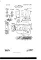
- FIG. 12 shows in longitudinal section part of a steam-turbine having guideblades constructed andtarranged according to this invention
- Fig. 13 is a sectional plan of part of such turbine on the line C O of Fig. -l2.
- suitable lengths are cut from a parallel strip of materialsuch, for example, as brass, delta metal, or steelone side of which has been made concave by drawing, milling, rolling, orotherwise to accurately correspond in shape to the concave side of the finished blade.
- Each length of metal is then passed between a pair of milling-cutters, by which the ends are cut to an exact length to form a blank from which the improved blade is to be made.
- the said ends may at the same time be grooved, beveled, rabbeted, or otherwise shaped to accurately fit the cross-section of the circular or partlycircular or annular groove or port. provided in the turbine-case or in the spindle to receive them.
- a blank athus formed is shown in Figs.
- each blade is then milled convex to exactly the same curve as the concave side 0.
- the blade a is held slightly inclined, so that when finished the convex and concave surfaces 1) and c are not at equal distances apart along their length, but would meet at the center of the circle around which the blades are to be placed, so that if a number of blades at this stage of manufacture be placed together side by side, as shown in Figs.
- the finished blade at is taper in longitudinal section and of feather or concavo-convex shape in cross-section, with a fine forward or exit edge 7; and having on its convex side at its two ends two wings or projections m, that exactly fit the concave side of the next adjacent blade, and thus keep the two blades in exact relative position and at the same time form side or end walls to the passage-way it between the blades.
- the blades a are to be attached to the interior of a cylinder or to the circumference of a drum n, Fig. 9, their ends are inserted in an annular groove 0 or grooves formed in the circumference of the said cylinder or drum.
- the wings or projections m at the fixed ends of the blades are, as shown in Fig.
- the blades (2., being made on an interchangeable system, can by removing the stopping-piece u be readily exchanged for others of difierent dimensions.
- the bladesa may, however, be fixed in place in each port or opening q in any other convenient way.
- Figs. 12 and 13 show one construction of turbine embodying the present invention.
- 0' r are annular-shaped Walls fixed within the turbine-casing w and formed at their peripheries with the arc-shaped opening q, in which the guide-blades a are detachably fixed, as hereinbefore described, and 0c is a spindle that extends through the said casing and transverse Walls and has fixed to it turbine wheels that are arranged to rotate in proximity to the said walls and blades and each of which comprises an annular carrier y and a ring of blades 2: of concavo-convex section.
- the blades 2 in each ring thereof are fixed to the outer periphery of the corresponding carrier y and are provided with annular bafflers 2 .2 that are made of greater width than the said blades .2, are fixed to the inner and outer ends of such blades, and are arranged to rotate in proximity to the adjacent wall 1', as described in the specification of another application for Letters Patent filed by me of even date herewith, Serial No. 75,649.
- ff are concentrically-arranged annular baffiing devices carried by the rotary and fixed parts and serving to retard flow of motive from the turbine-chamber rat one side of each wall r through the central opening r in such wall to the adjacent chamber 0" at the opposite side of such wall, as described in my said other specification.
- a fluid-pressure turbine comprising a casing, stationary guide-blades fixed therein, a rotary spindle extending through said casing, and turbine wheels carried by said spindle and arranged to rotate in proximity to said guide-blades, said guide-blades fitting one against the other at their ends and each having therein a notch or recess arranged to form with the adjacent blade a passage of the required cross-section for motive fluid.
- a fluid-pressure turbine comprising a casing,stationary blade-carriers fixed therein, guide-blades fixed to said carriers, a rotary spindle extending through said casing, and turbine wheels carried by said spindle and arranged to rotate inproximity to said guideblades, said guide-blades fitting one against the other at their ends and each having therein a notch or recess arranged to form with the adjacent blade, a passage of the required cross-section for motive fluid.
- a fluid-pressure turbine comprising a casing, transverse walls or partitions fixed within said casing, guide-blades fixed to said walls or partitions, a rotary spindle extending through said casing, and turbine wheels carried by said spindle and arranged to rotate in proximity to said guide-blades, said guide- IIO blades fitting oneagainst the other at their ends and each having therein a notch or recess arranged to form with the adjacent blade, a passage of the required cross-section for motive fluid.
- a fluid-pressure turbine comprising a casing, groups of guide-blades fixed therein,
- a rotary spindle extending through said .casing, and turbine wheels carried by said spindle and arranged to rotate in proximity to said guide-blades, the guide-blades in each group thereof being of sector-like shape fitting one against the other, and having between them passage-ways each made to gradually increase in cross-sectional area toward the outlet end, as set forth.
- a fluid-pressure turbine comprising a casing, blade-carriers fixed therein, groups of guide-blades detachably fixed in arc-shaped notches or openings in said carriers, a spindle extending through said casing and carriers, and turbine wheels fixed to said spindle, and arranged to rotate in proximity to said carriers and groups of guide-blades, the guide-blades in each group fitting one against the, other and having passages of graduallyincreasing cross-sectional area formed between them at parts thereof between their ends.
- a fluid-pressure turbine comprising a casing, blade-carriers fixed therein, groups-of guide-blades detachably fixed in arc-shaped notches or openings in said carriers, a spindle extending through said casing and carriers, and turbine wheels fixed to said spindle and arranged to rotate in proximity to said carriers and groups of guide-blades, the guide-bladesin each group fitting one against the other at their ends and each formed on one side with a notch of gradually-increasing cross-sectional area and with a fine edge at the forward or exit end of the said notch.
- a fluid-pressure turbine comprising a casing, blade-carriers fixed therein, groups of guide-blades detachably fixed in arc-shaped notches or openings in said carriers, a spindle extending through said casing, and carriers, and turbine wheels fixed to said spindle and arranged to rotate in proximity to said carriers and groups of guide-blades, the guide-blades in each group fitting one against the other and having passages for motive fluid between them, each passage being of gradually-increasing size toward 'the exit thereof, and ofapproximately equal crosssection from the inner to the outer end thereof in a radial direction.
- a fluid-pressure turbine comprising a casing, blade carriers fixed therein, and guide-blades fixedto said carriers, a spindle extending through said casing, and turbine wheels fixed to said spindle and arranged to rotate in proximity to said guide-blades, each of said blades being of concavo-convex section and having on its convex side two projections that exactly fit the concave side of the next adjacent blade, and an intermediate notch, substantially as described.
- a fluid-pressure turbine comprising a casing, blade carriers fixed 'therein, and guide-blades fixed to said carriers, a spindle extending through said casing, and turbine wheels fixed to said spindle and arranged to rotate in proximitytosaid guide-blades, each of said blades being of concavo-convex section and having on its convex side two projections that exactly fit the concave side of' the next adjacent blade, and an intermediate notch and a fine edge at the forward or exit end of said notch, substantially as described. 10.
- a fluid-pressure turbine comprising a casing, annular guide blade carriers fixed transversely therein radially-arranged guideblades fixed to said carriers and fitting one against the other, a spindle extending through said casing, and turbine wheels fixed to said spindle and arranged to rotate in proximity to said carriers and guide-blades, each of said blades being taper in longitudinal section and of concavo-convex cross-section and having on its convex side at its ends, two projections fitting against the concave side of the next adjacent blade and an intermediate notch with a fine edge at the forward or exit end of said notch, substantially as described.
- a fluid-pressure turbine comprising a casing, annular transverse walls fixed therein and having arc-shaped openings formed therethrough near their outer peripheries, groups of radially-arran ged guide-blades arranged in said openings and having their ends engaged with the inner and outer peripheries of said openings, a removable filling-piece between the last blade in each group and the adjacent end of the corresponding opening, a spindle extending through said casing and walls, and turbine wheels fixed to said spindle and arranged to rotate in proximity to said Walls and guide-blades, each guide-blade being taper in longitudinal section and concavo-convex in cross-section and having on its convex side at its ends, two projections fitting against the concave side of the next adjacent blade or'filling-piece and an intermediate notch with a fine edge at the forward or exit end of said notch, substantially as described.
- a turbine-blade taper in longitudinal section and concavo-convex in cross-section, and having on its convex side at its ends, two wings or projections with an intermediate notch or recess to form a passage-way of the section set forth, and a fine edge at the forward or exit end of said notch or recess, substantially as described.
Landscapes
- Engineering & Computer Science (AREA)
- Mechanical Engineering (AREA)
- General Engineering & Computer Science (AREA)
- Turbine Rotor Nozzle Sealing (AREA)
Description
Patented Oct. 28, 1902;
No. 7l2,369.
H. F. FULLAGAR. FLUID PRESSURE TURBINE.
(Application fled Sept. 1 6, 1901'.)
2 Sheets-Shoot No Modal.)
No. 712,369. Patentedflct. 28, I902. .H. F; FULLAGAR.
FLU-ID PRES-SURE TURBINE.
(Aiaplicatim; filed Sept. 16, 1901.)
2 Sheets-Sheet 2.
(No Model.)
UNITED STATES PATENT ()FFI'CE.
HUGH FRANCIS FULLAGAR, OF NEWCASTLE-UPON-TYNE, ENGLAND.
FLUID-PRESSURE TURBINE.
SPECIFICATION forming part of Letters Patent N 0. 712,369, dated October 28, 1902.
Application filed September 16, 190 1. Serial No. 75,650. (No model.)
To all whom it may concern:
Be it known that I, HUGH FRANCIS FULLA- GAR, a subject of the King of Great Britain and Ireland,residing at Newc'astle-upon-Tyne, in the county of Northumberland, England, have invented Improvements in orRelating to Fluid-Pressure Turbines, of which the followthe required manner upon the sets of rotary turbine-blades. i
According to this invention the blades are so shaped that the several streams of steam issuing from between them unite to form a practically solid parallel annular jet the stream-lines of which are nearly all parallel.
to one another and which has therefore little tendency to diverge or spread laterally, whereby the liability to serious leakage that obtains with some constructions of turbine is avoided and the efficiency of the turbine considerably increased. For this purpose the passage-way betweeneach pair of blades is made to continually increase in transverse or cross-sectional area from the inlet or from a point near the inlet to the exit, the ratio of this increase being such that the working fluid in its passage will expand fully to the increased volume, corresponding to the diminished pressure before leaving the said passage-way, so that having then little or no further tendency to spread laterally it will issue in a practically parallel jet in a given direction with the full velocity due to the drop in pressure. When the ratio of expansion is high and the velocity great, it is of importance that the blades should be accurately shaped and exactly spaced, and, further, when the blades are placed radially it is desirable to slightly taper each blade in the direction of its length in order that the ratio of expansion of the passage-way between any pair of blades may be the same for cross-sections at dilferent radialdistances from the axis of the turbine, the sides of the passage-way in any section thereof at right angles to the axis of the turbine being parallel to one another. For this purpose the blades are constructed in the improved manner which will now be explained with reference to the accompanying illustrative drawings, wherein- Figures 1 and 2 show, respectively, in side elevation and plan a metal blank from which a blade is to be made. Figs. 3 and 4 show, respectively, in side elevation and plan a number of such blanks fitted together after being subjected to a preliminary shaping operation. Fig. 5 shows in side elevation a finished blade, and Fig. 6 shows in side elevation a number of such finished blades mounted in position for use in a ring. Figs. 7 and 8 are sections on the lines A A and B B, respectively, of Fig. 6. Figs. 9, 10, and 11 are similar views to Fig. 8, showing other Ways of mounting the blades in a ring or holder. Fig. 12 shows in longitudinal section part of a steam-turbine having guideblades constructed andtarranged according to this invention, and Fig. 13 is a sectional plan of part of such turbine on the line C O of Fig. -l2.
' To form the blades, suitable lengths are cut from a parallel strip of materialsuch, for example, as brass, delta metal, or steelone side of which has been made concave by drawing, milling, rolling, orotherwise to accurately correspond in shape to the concave side of the finished blade. Each length of metal is then passed between a pair of milling-cutters, by which the ends are cut to an exact length to form a blank from which the improved blade is to be made. The said ends may at the same time be grooved, beveled, rabbeted, or otherwise shaped to accurately fit the cross-section of the circular or partlycircular or annular groove or port. provided in the turbine-case or in the spindle to receive them. A blank athus formed is shown in Figs. 1 and 2, its convex and concave sides I) and 0 corresponding to those of the strip of metal from which it is cut, and 01 being rectangular notches cut in its top and bottom ends. The back I) of each blade is then milled convex to exactly the same curve as the concave side 0. During this operation the blade a is held slightly inclined, so that when finished the convex and concave surfaces 1) and c are not at equal distances apart along their length, but would meet at the center of the circle around which the blades are to be placed, so that if a number of blades at this stage of manufacture be placed together side by side, as shown in Figs. 3 and 4, they will form practically a solid ring, the concave side 0 of each blade exactly fitting the convex side I? of the preceding blade, with no opening whatever between them. The blades Ct are then each held in an inclined position a second time under a milling-cutter like the one above mentioned, but somewhat narrower than the length of the blade and controlled by another templet or copy, like f, but having a different profile, by which a portion b of the back or convex side I) of the blade between its ends is milled down to a different contour, such as to form when two blades are placed together, as shown in Figs. 6 and 7, the required passage-way h between them. Thus the finished blade at is taper in longitudinal section and of feather or concavo-convex shape in cross-section, with a fine forward or exit edge 7; and having on its convex side at its two ends two wings or projections m, that exactly fit the concave side of the next adjacent blade, and thus keep the two blades in exact relative position and at the same time form side or end walls to the passage-way it between the blades. When the blades a are to be attached to the interior of a cylinder or to the circumference of a drum n, Fig. 9, their ends are inserted in an annular groove 0 or grooves formed in the circumference of the said cylinder or drum. The wings or projections m at the fixed ends of the blades are, as shown in Fig. 9, made of sufficient depth to fill the grooves to the surface of the cylinder or drum and be there secured by any suitable means-as, for example, by calking a narrow strip p of duetile metal into the groove alongside them. When, however, the blades are to be placed in a segmental-shaped port or opening q, formed in a stationary transverse wall '1" of the turbine-case, as shown in Figs. 6, 7, and S, the circular edges of such a port or opening may be formed with grooves s, Fig. 10, or with ribs, webs, or flanges t, Figs. 6, 7, 8, and 11, to retain the blades a, which are then shaped, as shown, to fit such edges, as before described, and are secured therein in any suitable wayas, for example, by cutting away a portion of the webs or flanges at one end of each port or opening q, so as to form small gaps q, through which the blades can be inserted,and then moved along the port or opening until the latter has been filled up to the ends of the ribs or flanges t, after which the end of the port or opening q is filled by a stopping-piece, such as 10, Figs. 6 and 7, secured in place by one or more screws '0 or other suitable means. In this case the blades (2., being made on an interchangeable system, can by removing the stopping-piece u be readily exchanged for others of difierent dimensions. The bladesa may, however, be fixed in place in each port or opening q in any other convenient way.
Figs. 12 and 13 show one construction of turbine embodying the present invention.
0' r are annular-shaped Walls fixed within the turbine-casing w and formed at their peripheries with the arc-shaped opening q, in which the guide-blades a are detachably fixed, as hereinbefore described, and 0c is a spindle that extends through the said casing and transverse Walls and has fixed to it turbine wheels that are arranged to rotate in proximity to the said walls and blades and each of which comprises an annular carrier y and a ring of blades 2: of concavo-convex section. The blades 2 in each ring thereof are fixed to the outer periphery of the corresponding carrier y and are provided with annular bafflers 2 .2 that are made of greater width than the said blades .2, are fixed to the inner and outer ends of such blades, and are arranged to rotate in proximity to the adjacent wall 1', as described in the specification of another application for Letters Patent filed by me of even date herewith, Serial No. 75,649. ff are concentrically-arranged annular baffiing devices carried by the rotary and fixed parts and serving to retard flow of motive from the turbine-chamber rat one side of each wall r through the central opening r in such wall to the adjacent chamber 0" at the opposite side of such wall, as described in my said other specification.
What I claim is 1. A fluid-pressure turbine, comprising a casing, stationary guide-blades fixed therein, a rotary spindle extending through said casing, and turbine wheels carried by said spindle and arranged to rotate in proximity to said guide-blades, said guide-blades fitting one against the other at their ends and each having therein a notch or recess arranged to form with the adjacent blade a passage of the required cross-section for motive fluid.
2. A fluid-pressure turbine, comprising a casing,stationary blade-carriers fixed therein, guide-blades fixed to said carriers, a rotary spindle extending through said casing, and turbine wheels carried by said spindle and arranged to rotate inproximity to said guideblades, said guide-blades fitting one against the other at their ends and each having therein a notch or recess arranged to form with the adjacent blade, a passage of the required cross-section for motive fluid.
3. A fluid-pressure turbine, comprising a casing, transverse walls or partitions fixed within said casing, guide-blades fixed to said walls or partitions, a rotary spindle extending through said casing, and turbine wheels carried by said spindle and arranged to rotate in proximity to said guide-blades, said guide- IIO blades fitting oneagainst the other at their ends and each having therein a notch or recess arranged to form with the adjacent blade, a passage of the required cross-section for motive fluid.
4. A fluid-pressure turbine comprising a casing, groups of guide-blades fixed therein,
a rotary spindle extending through said .casing, and turbine wheels carried by said spindle and arranged to rotate in proximity to said guide-blades, the guide-blades in each group thereof being of sector-like shape fitting one against the other, and having between them passage-ways each made to gradually increase in cross-sectional area toward the outlet end, as set forth.
5. A fluid-pressure turbine comprising a casing, blade-carriers fixed therein, groups of guide-blades detachably fixed in arc-shaped notches or openings in said carriers, a spindle extending through said casing and carriers, and turbine wheels fixed to said spindle, and arranged to rotate in proximity to said carriers and groups of guide-blades, the guide-blades in each group fitting one against the, other and having passages of graduallyincreasing cross-sectional area formed between them at parts thereof between their ends.
6. A fluid-pressure turbine comprising a casing, blade-carriers fixed therein, groups-of guide-blades detachably fixed in arc-shaped notches or openings in said carriers, a spindle extending through said casing and carriers, and turbine wheels fixed to said spindle and arranged to rotate in proximity to said carriers and groups of guide-blades, the guide-bladesin each group fitting one against the other at their ends and each formed on one side with a notch of gradually-increasing cross-sectional area and with a fine edge at the forward or exit end of the said notch.
7. A fluid-pressure turbine comprising a casing, blade-carriers fixed therein, groups of guide-blades detachably fixed in arc-shaped notches or openings in said carriers, a spindle extending through said casing, and carriers, and turbine wheels fixed to said spindle and arranged to rotate in proximity to said carriers and groups of guide-blades, the guide-blades in each group fitting one against the other and having passages for motive fluid between them, each passage being of gradually-increasing size toward 'the exit thereof, and ofapproximately equal crosssection from the inner to the outer end thereof in a radial direction.
8. A fluid-pressure turbine comprising a casing, blade carriers fixed therein, and guide-blades fixedto said carriers, a spindle extending through said casing, and turbine wheels fixed to said spindle and arranged to rotate in proximity to said guide-blades, each of said blades being of concavo-convex section and having on its convex side two projections that exactly fit the concave side of the next adjacent blade, and an intermediate notch, substantially as described.
9. A fluid-pressure turbine comprising a casing, blade carriers fixed 'therein, and guide-blades fixed to said carriers, a spindle extending through said casing, and turbine wheels fixed to said spindle and arranged to rotate in proximitytosaid guide-blades, each of said blades being of concavo-convex section and having on its convex side two projections that exactly fit the concave side of' the next adjacent blade, and an intermediate notch and a fine edge at the forward or exit end of said notch, substantially as described. 10. A fluid-pressure turbine comprising a casing, annular guide blade carriers fixed transversely therein radially-arranged guideblades fixed to said carriers and fitting one against the other, a spindle extending through said casing, and turbine wheels fixed to said spindle and arranged to rotate in proximity to said carriers and guide-blades, each of said blades being taper in longitudinal section and of concavo-convex cross-section and having on its convex side at its ends, two projections fitting against the concave side of the next adjacent blade and an intermediate notch with a fine edge at the forward or exit end of said notch, substantially as described.
11. A fluid-pressure turbine comprising a casing, annular transverse walls fixed therein and having arc-shaped openings formed therethrough near their outer peripheries, groups of radially-arran ged guide-blades arranged in said openings and having their ends engaged with the inner and outer peripheries of said openings, a removable filling-piece between the last blade in each group and the adjacent end of the corresponding opening, a spindle extending through said casing and walls, and turbine wheels fixed to said spindle and arranged to rotate in proximity to said Walls and guide-blades, each guide-blade being taper in longitudinal section and concavo-convex in cross-section and having on its convex side at its ends, two projections fitting against the concave side of the next adjacent blade or'filling-piece and an intermediate notch with a fine edge at the forward or exit end of said notch, substantially as described.
12. As a new article of manufacture, a turbine-blade of concavo-convex cross-section and having on its convex side at its ends, two projections with an intermediate notch to form a passage-way of the required section, substantially as described.
13. As a new article of manufacture, a turbine-blade taper in longitudinal section and concavo-convex in cross-section, and having on its convex side at its ends, two wings or projections with an intermediate notch or recess to form a passage-way of the section set forth, and a fine edge at the forward or exit end of said notch or recess, substantially as described.
14. As a new article of manufacture, a turbine-blade taper in longitudinal section, con- 1 Signed at Newcastle-upon -'1yne, in the cavo-oonvex in cross-section, and notched at I county of Northumberland, this 27th day of 1c the ends, and the convex side of said blade August, 1901. having two end Wings or projections with an I intermediate notch or groove to form a pasl HUGH FRANCIS FULLAGAR' sage-Way of the section set forth, and a fine edge at the forward or exit end of said notch or recess, substantially as described.
Witnesses:
W. SPELMAN BURTON, PERCY OoRDER.
Priority Applications (1)
| Application Number | Priority Date | Filing Date | Title |
|---|---|---|---|
| US7565001A US712369A (en) | 1901-09-16 | 1901-09-16 | Fluid-pressure turbine. |
Applications Claiming Priority (1)
| Application Number | Priority Date | Filing Date | Title |
|---|---|---|---|
| US7565001A US712369A (en) | 1901-09-16 | 1901-09-16 | Fluid-pressure turbine. |
Publications (1)
| Publication Number | Publication Date |
|---|---|
| US712369A true US712369A (en) | 1902-10-28 |
Family
ID=2780893
Family Applications (1)
| Application Number | Title | Priority Date | Filing Date |
|---|---|---|---|
| US7565001A Expired - Lifetime US712369A (en) | 1901-09-16 | 1901-09-16 | Fluid-pressure turbine. |
Country Status (1)
| Country | Link |
|---|---|
| US (1) | US712369A (en) |
-
1901
- 1901-09-16 US US7565001A patent/US712369A/en not_active Expired - Lifetime
Similar Documents
| Publication | Publication Date | Title |
|---|---|---|
| ITCO20130004A1 (en) | METHOD TO REALIZE A IMPELLER FROM SECTOR SEGMENTS | |
| GB1376966A (en) | Porous abradable seal structures | |
| US1749528A (en) | Blading for reaction turbines | |
| US2264877A (en) | Elastic fluid turbine diaphragm | |
| US1022683A (en) | Turbine. | |
| US712369A (en) | Fluid-pressure turbine. | |
| US2225769A (en) | Turbine blade | |
| US3038699A (en) | Nozzle ring assembly | |
| US1475212A (en) | Elastic-fluid turbine | |
| US927658A (en) | Steam-turbine. | |
| US1266973A (en) | Nozzle construction for elastic-fluid turbines. | |
| US3279751A (en) | Shrouded turbine or compressor blade | |
| US1070309A (en) | Steam-turbine. | |
| US809277A (en) | Turbine. | |
| US2331076A (en) | Turbine nozzle ring | |
| US735107A (en) | Turbine. | |
| US696867A (en) | Compound steam-turbine. | |
| US1286204A (en) | Steam-turbine. | |
| US1298524A (en) | Elastic-fluid turbine. | |
| US1820009A (en) | Rotary pump | |
| US953552A (en) | Fluid-pressure turbine. | |
| US1473690A (en) | Serial-flow turbine | |
| US767367A (en) | Turbine-blade. | |
| USRE12317E (en) | Signor to john tweedy | |
| US860573A (en) | Turbine. |