US6983609B2 - Heat driven acoustic orifice type pulse tube cryocooler - Google Patents
Heat driven acoustic orifice type pulse tube cryocooler Download PDFInfo
- Publication number
- US6983609B2 US6983609B2 US10/643,239 US64323903A US6983609B2 US 6983609 B2 US6983609 B2 US 6983609B2 US 64323903 A US64323903 A US 64323903A US 6983609 B2 US6983609 B2 US 6983609B2
- Authority
- US
- United States
- Prior art keywords
- driving gas
- pulse tube
- heat exchanger
- gas
- cold
- Prior art date
- Legal status (The legal status is an assumption and is not a legal conclusion. Google has not performed a legal analysis and makes no representation as to the accuracy of the status listed.)
- Expired - Fee Related, expires
Links
Images


Classifications
-
- F—MECHANICAL ENGINEERING; LIGHTING; HEATING; WEAPONS; BLASTING
- F25—REFRIGERATION OR COOLING; COMBINED HEATING AND REFRIGERATION SYSTEMS; HEAT PUMP SYSTEMS; MANUFACTURE OR STORAGE OF ICE; LIQUEFACTION SOLIDIFICATION OF GASES
- F25B—REFRIGERATION MACHINES, PLANTS OR SYSTEMS; COMBINED HEATING AND REFRIGERATION SYSTEMS; HEAT PUMP SYSTEMS
- F25B9/00—Compression machines, plants or systems, in which the refrigerant is air or other gas of low boiling point
- F25B9/14—Compression machines, plants or systems, in which the refrigerant is air or other gas of low boiling point characterised by the cycle used, e.g. Stirling cycle
- F25B9/145—Compression machines, plants or systems, in which the refrigerant is air or other gas of low boiling point characterised by the cycle used, e.g. Stirling cycle pulse-tube cycle
-
- F—MECHANICAL ENGINEERING; LIGHTING; HEATING; WEAPONS; BLASTING
- F25—REFRIGERATION OR COOLING; COMBINED HEATING AND REFRIGERATION SYSTEMS; HEAT PUMP SYSTEMS; MANUFACTURE OR STORAGE OF ICE; LIQUEFACTION SOLIDIFICATION OF GASES
- F25B—REFRIGERATION MACHINES, PLANTS OR SYSTEMS; COMBINED HEATING AND REFRIGERATION SYSTEMS; HEAT PUMP SYSTEMS
- F25B2309/00—Gas cycle refrigeration machines
- F25B2309/14—Compression machines, plants or systems characterised by the cycle used
- F25B2309/1403—Pulse-tube cycles with heat input into acoustic driver
-
- F—MECHANICAL ENGINEERING; LIGHTING; HEATING; WEAPONS; BLASTING
- F25—REFRIGERATION OR COOLING; COMBINED HEATING AND REFRIGERATION SYSTEMS; HEAT PUMP SYSTEMS; MANUFACTURE OR STORAGE OF ICE; LIQUEFACTION SOLIDIFICATION OF GASES
- F25B—REFRIGERATION MACHINES, PLANTS OR SYSTEMS; COMBINED HEATING AND REFRIGERATION SYSTEMS; HEAT PUMP SYSTEMS
- F25B2309/00—Gas cycle refrigeration machines
- F25B2309/14—Compression machines, plants or systems characterised by the cycle used
- F25B2309/1407—Pulse-tube cycles with pulse tube having in-line geometrical arrangements
-
- F—MECHANICAL ENGINEERING; LIGHTING; HEATING; WEAPONS; BLASTING
- F25—REFRIGERATION OR COOLING; COMBINED HEATING AND REFRIGERATION SYSTEMS; HEAT PUMP SYSTEMS; MANUFACTURE OR STORAGE OF ICE; LIQUEFACTION SOLIDIFICATION OF GASES
- F25B—REFRIGERATION MACHINES, PLANTS OR SYSTEMS; COMBINED HEATING AND REFRIGERATION SYSTEMS; HEAT PUMP SYSTEMS
- F25B2309/00—Gas cycle refrigeration machines
- F25B2309/14—Compression machines, plants or systems characterised by the cycle used
- F25B2309/1413—Pulse-tube cycles characterised by performance, geometry or theory
-
- F—MECHANICAL ENGINEERING; LIGHTING; HEATING; WEAPONS; BLASTING
- F25—REFRIGERATION OR COOLING; COMBINED HEATING AND REFRIGERATION SYSTEMS; HEAT PUMP SYSTEMS; MANUFACTURE OR STORAGE OF ICE; LIQUEFACTION SOLIDIFICATION OF GASES
- F25B—REFRIGERATION MACHINES, PLANTS OR SYSTEMS; COMBINED HEATING AND REFRIGERATION SYSTEMS; HEAT PUMP SYSTEMS
- F25B2309/00—Gas cycle refrigeration machines
- F25B2309/14—Compression machines, plants or systems characterised by the cycle used
- F25B2309/1424—Pulse tubes with basic schematic including an orifice and a reservoir
Definitions
- This invention relates to a cryocooler cooling a superconducting material using an inert gas, and more particularly relates to a heat driven acoustic orifice type pulse tube cryocooler for installing metal knit within a driving section cooling a driving gas of an application device using a principle of high temperature superconductivity, and then homogeneously heating the driving gas by way of premixed combustion.
- a cryocooler is applied to a field of infrared rays sensor cooling, a field of cryooperating and MRI, a field of electronic equipments such as RF filter for mobile communication, and a filed of a superconductivity electric power application device, which, for example, are driven at about 77K ( ⁇ 196° C.).
- the temperature at about 77K ( ⁇ 196° C.) means a cooling temperature of high temperature superconducting material using a liquified nitrogen gas.
- the cyrocooler cooling the superconducting material is classified as Stirling cryocooler, Joule-Thomson cryocooler, Gifford-McMahon cryocooler, and Pulse Tube cryocooler, depending upon a thermodynamic cycle.
- the Gifford-McMahon cryocooler has some problems that, since each of a high temperature part and a low temperature part is provided with one or more driven part, operating efficiency is low, cooling capacity is small, and a maintenance and repair cost is very high.
- FIG. 1 is a constitutional view for explaining a operation principle of the prior Stirling cryocooler.
- the cryocooler consists of a compression space 1 a and a expansion space 1 b which each volume of operating gas thereof is changed by movement of a piston 1 c , a hot heat exchanger 5 a , a cold heat exchanger 5 b , and a regenerator 3 .
- the heat of the operating gas is transferred to an inner matrix of the regenerator 3 via the hot heat exchanger 5 a .
- the heat from the matrix of the regenerator 3 is transferred to the cold heat exchanger 5 b , thereby the cold heat exchanger 5 b has a higher temperature Tc than the prior temperature.
- the temperature Tc of the cold heat exchanger 5 b changes the temperature of the expansion space 1 b .
- the temperature of the operating gas within the expansion space 1 b into which the heat of the comparatively higher temperature is input becomes immediately higher, and the operating gas is expanded.
- the operating gas within the compressing space 1 a receives a predetermined heat from the hot heat exchanger 5 a receiving heat from the matrix of the regenerator 3 and having a higher temperature, and has a temperature T H of the hot heat exchanger 5 a.
- a heat transfer quantity that the operating gas receives from the regenerator 3 during the steps S 40 to S 10 is equal to a heat transfer quantity that the operating gas of the compressing space transfers to the regenerator 3 during S 20 to S 30 .
- a sum of the heat transfer quantity that the regenerator 3 gives and takes every cycle is numerically “0”.
- the Stirling cryocooler carrying out a thermal dynamic cycle in regular sequence of S 10 , S 20 , S 30 , S 40 , and S 10 may have a cold effect receiving heat from the low temperature part and emitting heat to the high temperature part.
- the Stirling cryocooler has a complex structure, since each of a high temperature part and a low temperature part thereof is provided with an additional driving part. Further, the operation reliability is considerably lower due to friction between a sealing member of displacement apparatus such as a piston and a cylinder at low temperature in case of being driven for a long time
- the Pulse Tube cryocooler which is transformed from the Stirling cryocooler, is classified as a basic type, an orifice type, and a double inlet type. Further, it is classified as a resonance tube type, 2 valve-type, 4 valve-type and a mixed type according to a structure for a freezing temperature and a freezing capacity.
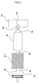
- FIG. 2 is a constitutional view of the prior orifice type pulse tube cyrocooler.
- this type of cyrocooler After a gas having a predetermined temperature is periodically poured into a tube having a closed end, the cyrocooler is operated according to the change of pressure of a poured gas. In case of having a little turbulent current in the gas flow, it uses a heat pumping effect enabling to obtain very high temperature gradient.
- This orifice type pulse tube cyrocooler is consisted of a compressing section 2 a , an aftercooler 5 c subsequently connected to the compressing section 2 a , a regenerator 3 - 1 , a pulse tube 7 a , a diffuser 7 b , a cold gas reservoir 7 d , and an orifice 7 c installed between the diffuser 7 b and the cold gas reservoir 7 d.
- the compressing section 2 a is changed into a expanding section according to its motion, and it is provided with a reciprocating piston 2 c within the inside.
- the pulse tube 7 a have a virtual gas piston.
- the combination structure of the pulse tube 7 a , a hot heat exchanger 5 a and the cold gas reservoir 7 d corresponds to the expansion space 1 b of the Stirling cryocooler.
- phase difference (generated from the relationship of pressure and mass flow quantity within the pulse tube) between the piston 2 c of the compressing section 2 a and the virtual gas piston of the pulse tube is generated between the pulse tube 7 a and the cold gas reservoir 7 d.
- the phase difference generated from the orifice type pulse tube cryocooler is smaller than the phase difference generated from the piston 1 c of the expansion space 1 b of the Stirling cryocooler. Therefore, the cooling effect of the orifice type pulse tube cryocooler is comparatively higher.
- the orifice type pulse tube cryocooler requires more mass flow quantity per cold capacity than the Stirling cryocooler as to the amplitude of pressure change.
- the pulse tube cryocooler is provided with only one driver. Therefore, the orifice type pulse tube cryocooler has a more simple structure and is inexpensive for the maintenance and repair cost even an operation for a long time in comparison with the Stirling cryocooler, but still has a problem that the vibration occurs.
- FIG. 3 is a constitutional view of the prior heat driven acoustic pulse tube cryocooler.
- This crycooler is consisted of a driving gas reservoir 9 a , an electric heater 9 b subsequently connected to the driving gas reservoir 9 a , a cylindrical tube 9 c , a heat-acoustic driver 9 d , a drive stack 9 e , a cold stack tube 9 f , and a pulse tube 7 e .
- the other side of pulse tube 7 e is provided with a diffuser 7 b and a cold gas reservoir 7 g.
- an electrical heating source of the electric heater 9 b generates a pressure pulse of a driving gas reserved in the driving gas reservoir 9 a , the pressure pulse then adiabatically compresses and expands the gas. Thereafter, the temperature of the gas is changed, and then heat corresponding to the temperature of the gas is transferred to the drive stack 9 e and the cold stack tube 9 f . As such a result, the cryocooler is operated.
- the heat transferred to the pulse tube 7 e is exchange in the pulse tube 7 e due to a circulation of a coolant within the pulse tube 7 e , and thus the heat is emitted from the pulse tube 7 e to the outside.
- this type of cyrocooler has a limited cooling capacity due to a limitation of capacity of the electrical heat source, since a very low temperature is realized by changing the electrical heat source into the acoustic energy.
- a first object of the invention is to provide a heat driven acoustic orifice type pulse tube cryocooler for having a combustion structure heating homogeneously an operating gas using a metal knit woven with metal fiber.
- a second object of the invention is to provide a heat driven acoustic orifice type pulse tube cryocooler for having a combustion structure heating homogeneously an operating gas using a metal knit woven with metal fiber and overcoming vibration, noise, reliability deterioration, and low capacity generated from a heat driven acoustic process.
- a third object of the invention is to provide a heat driven acoustic orifice type pulse tube cryocooler for having a combustion structure heating homogeneously an operating gas using a metal knit woven with metal fiber in order to be utilized as a cryocooler for cooling a superconductivity application device requiring a small capacity and for a superconductivity electronic equipments such as a field of infrared rays sensor cooling, a field of cryooperating and MRI, a field of electronic equipments such as RF filter for mobile communication, and a filed of a superconductivity electric power application device.
- the inventive cryocooler comprises a driver 10 generating a flame radiating heat having a predetermined temperature, homogeneously heating a driving gas, and adiabatically compressing the driving gas so that the driving gas generates an acoustic having a predetermined frequency; a regenerator 20 receiving the driving gas output from the driver, and cooling the driving gas; a pulse tube 40 receiving the cold driving gas output from the generator, adiabatically compressing the driving gas, and generating the driving gas having a high temperature; a cold reservoir 60 receiving the high temperature driving gas output from the pulse tube, and adiabatically expanding the driving gas; a second hot heat exchanger 30 installed between the generator 20 and the pulse tube 40 , and exchanging heat with the outside; a cold heat exchanger installed between the pulse tube 40 and the cold reservoir 60 , and exchanging heat with the outside; and an orifice 62 installed within the cold reservoir, the orifice controlling an amount of the driving gas running between the cold reservoir 60 and the pulse tube 40 to constantly maintain a pressure of the cold
- FIG. 1 is a constitutional view for explaining an operation principle of the prior Stirling cryocooler.
- FIG. 2 is a constitutional view of the prior orifice type pulse tube cyrocooler.
- FIG. 3 is a constitutional view of the prior heat driven acoustic pulse tube cryocooler
- FIG. 4 is a constitutional view of a heat driven acoustic orifice type pulse tube cryocooler according to the invention.
- FIG. 5 is a constitutional view for showing specifically a driver in FIG. 4 .
- FIG. 6 is a photograph enlarging a surface of a structure of a metal knit according to the invention.
- FIG. 4 is a constitutional view of a heat driven acoustic orifice type pulse tube cryocooler according to the invention
- FIG. 5 is a constitutional view for showing specifically a driver in FIG. 4 .
- a heat driven acoustic orifice type pulse tube cryocooler (hereinafter, referred to “cooler”) 100 according to the invention is an apparatus for accomplishing a cooling effect that a very low temperature, preferably about 77K ( ⁇ 196° C.), can be obtained, with an inert gas poured as a driving gas experiencing the process of adiabatic compression and adiabatic expansion to generate a change of the temperature and exchanging with heat the outside, using a vibration energy generated upon changing heat into acoustic.
- the cooler 100 comprises a driver 10 , as a heating source heating and pulsating the driving gas, changing the temperature of the driving gas by a sound wave generated from the driving gas upon heating and pulsating the driving gas by way of a premixed combustion, a regenerator 20 connected to the driver 10 by a post treatment heat exchanger 13 , a second hot heat exchanger 30 in which the driving gas output from the regenerator exchanges heat with the outside, a pulse tube 40 connected to the regenerator 20 by the second hot heat exchanger 30 , a cold heat exchanger 50 in which the driving gas output from the pulse tube exchanges heat with the outside, and the cold gas reservoir 60 connected to the pulse tube 40 by the cold heat exchanger 50 .
- a driver 10 as a heating source heating and pulsating the driving gas, changing the temperature of the driving gas by a sound wave generated from the driving gas upon heating and pulsating the driving gas by way of a premixed combustion
- a regenerator 20 connected to the driver 10 by a post treatment heat exchanger 13
- the driver 10 comprises a burner 11 into which a mixed gas (e.g. fuel and air) from the outside is input, a first hot heat exchanger 12 installed within the burner 11 , and having the driving gas, a metal knit 12 a surrounding the outer surface of the first hot heat exchanger 12 and installed at a predetermined distance from the inner wall surface of the burner 11 in order to homogeneously heat the driving gas, and a post treatment heat exchanger 13 mounted within the first hot heat exchanger 12 and exposed out of the burner 11 to be connected with the regenerator 20 to control a heat capacity transferred to the outside and the driving gas by way of heat transfer.
- a mixed gas e.g. fuel and air
- the first hot heat exchanger 12 has a cylindrical shape.
- the regenerator 20 has a structure that a plurality of plate 21 is piled up therein.
- the pulse tube 40 includes a stack 41 having thin plates 41 a piled up parallel to the flowing direction of the driving gas, and a diffuser 61 connected to the cold reservoir 60 via the cold heat exchanger 50 .
- connection portion between the diffuser 61 and the cold gas reservoir 60 is provided with an orifice 60 within the cold gas reservoir 60 .
- the orifice 62 serves to constantly maintain the pressure of the cold reservoir by controlling the amount of the driving gas reciprocating between the cold gas reservoir 60 and the pulse tube 40 .
- the driving gas is an inert gas, such as He or Ar.
- the driving gas is vibrated spontaneously if the driver 10 is heated, and then the pressure wave is generated.
- the pressure wave causes the driving gas to move in sequence of the post treatment heat exchanger 13 , the regenerator 20 , the second hot heat exchanger 30 , and the pulse tube 40 .
- the driver 10 heats the driving gas by generating a flame therein. If the driver generates the flame having the temperature of about 1000 ⁇ or more by way of premixed combustion to heat the driving gas, the driving gas within the first hot heat exchanger 12 generates the sound wave having the pressure of about 7,600 mmHg and the frequency of about 500 Hz.
- the metal knit 12 a is a heat transferring member manufactured with metal fiber.
- the flame generated by way of premixed combustion within the driver 10 contacts directly the surface of the metal knit 12 a , and then the surface of the first hot heat exchanger 12 is wholly and evenly heated. Thus, the time taken for heating the first hot heat exchanger 12 by the flame is saved. Since the metal fiber heats the surface of the first hot heat exchanger 12 by the latent heat, the metal knit realizes a heat transfer quantity of about 70% through the radiation.
- Table 1 shows the component parts and the content per weight % of the metal knit 12 .
- the metal knit 12 a according to the embodiment of the invention is woven, and then attached the surface of the first hot heat exchanger 12 .
- the shape of the metal knit 12 a is shown in FIG. 6 .
- the regenerator 20 causes the driving gas to exchange heat with the outside in the second hot heat exchanger 30 and the cold heat exchanger 50 in turn with the operating gas, which is input to the pulse tube 40 and passes through the second hot heat exchanger 30 after the driving gas having a predetermined frequency band from the driver 11 is input to the inside of the regenerator 20 , running between the regenerator 20 and the cold gas reservoir 60 .
- One side of stack 41 of the pulse tube 40 contacts with a driving gas having a comparatively lower temperature, and the other side of stack 41 contacts with a driving gas having a comparatively higher temperature.
- the one side of the stack 41 retains a heat of a comparatively lower temperature
- the other side of the stack 41 retains a heat of a comparatively higher temperature
- an inner pressure of the cold gas reservoir 60 is always constant.
- the flame is homogeneously transferred to the driving gas within the first hot heat exchanger 12 by way of radiation. Then, the driving gas is vibrated by the sound wave having the pressure of about 7,600 mmHg and the frequency of about 500 Hz, and then the temperature of the driving gas is raised through the adiabatic compression process due to the above vibration.
- the driving gas having the raised temperature transfer heat passing through the regenerator 20 and then is cooled to the gas of low temperature. At this time, the temperature of the cold gas becomes about 77K. Then, the driving gas of the low temperature is reached to the second hot heat exchanger 30 , and exchanges heat with the outside.
- the driving gas is heated passing through the stack 41 of the pulse tube 40 to have a high temperature, and then moved to orifice 62 .
- the cold heat exchanger 50 exchanges heat with the outside.
- the temperature of the driving gas flowed in the cold gas reservoir 60 via the orifice 62 is lower due to the adiabatic expansion. At this time, the above temperature is lower than that of the cold heat exchanger 50 . The driving gas with the lower temperature is moved again to the cold heat exchanger 50 , and then receives heat from the outside.
- the heated driving gas is moved again from the regenerator 20 to the second hot heat exchanger 30 .
- the heat transfer quantity which the driving gas receives from the regenerator 20 while the driving gas passes from the second hot heat exchanger 30 to the regenerator 20 is equal to the heat transfer quantity which the driving gas transfers to the regenerator 20 while the driving gas passes from to the regenerator 20 to the second hot heat exchanger 30 in the prior process. Therefore, a sum of the exchanged heat capacity per one cycle is numerically “0”.
- the driving gas runs between the second hot heat exchanger 30 and the cold heat exchanger 50 with existing in the status of the low temperature at one side of the stack 41 , whereas existing in the status of the high temperature at the other side of the stack 41 , centering around the stack 41 of the pulse tube 40 . Since the pulse tube is operated by the virtual gas piston, the driving gas repeats the process of the compression and expansion centering around the pulse tube
- the cooler according to the invention realizes the cooing principle that the heat from the low temperature side is emitted to the high temperature side with experiencing the above subsequent process.
- FIG. 6 is a photograph enlarging a surface of a structure of a metal knit according to the invention.
- the metal knit 12 a is attached to the surface of the first hot heat exchanger 12 of the driver 12 a .
- the metal knit 12 a radiates heat of the flame generated from the burner 11 , and then homogeneously transfers the heat to the driving gas within the first hot heat exchanger 12 .
- the metal knit 12 a is manufactured in the form of knit woven with the metal fiber of a plurality of strands, which is comparatively thin, but has a constant thickness.
- the metal knit 12 a is heated by the flame with covered to adhere closely to the surface of the first hot heat exchanger 12 , the heat is homogeneously transferred to the whole surface of the first hot heat exchanger 12 .
- the metal knit 12 a serves to comparatively enlarge the area of the first hot heat exchanger 12 contacted by the flame, it causes comparatively a quantity of heat to transfer to the first hot heat exchanger 12 .
- the length of the flame generated from the burner 11 can be reduced up to about 20 cm.
- inert gas such as He or Ar is illustrated as the driving gas in the embodiment of the invention, Ne or Xe except for the above inert gas, or a gas of mixing the inert gases may be used.
- metal knit 12 a woven with the metal fiber is illustrated to enclose the surface of the first hot heat exchanger 12 , a plurality of strands of metal fiber may be evenly attached to the surface of the first hot heat exchanger 12 .
- the metal fiber having a variety of shape may be manufactured by changing the content value of the component parts.
- a heat driven acoustic orifice type pulse tube cryocooler can be efficiently utilized in a superconductivity application device for requiring a small capacity and for a superconductivity electronic equipments, such as a field of infrared rays sensor cooling, a field of cryooperating and MRI, a field of electronic equipments such as RF filter for mobile communication, and a filed of a superconductivity electric power application device.
- a superconductivity electronic equipments such as a field of infrared rays sensor cooling, a field of cryooperating and MRI, a field of electronic equipments such as RF filter for mobile communication, and a filed of a superconductivity electric power application device.
- the driver can be driven as a single element, and the metal fiber of the driver cause the length of the flame to be reduced from about 150 cm in the prior art to about 20 cm, the vibration and noise is not only considerable reduced, but also the operation reliability and efficiency is higher and the cooling capacity is larger.
Landscapes
- Engineering & Computer Science (AREA)
- Physics & Mathematics (AREA)
- Mechanical Engineering (AREA)
- Thermal Sciences (AREA)
- General Engineering & Computer Science (AREA)
- Containers, Films, And Cooling For Superconductive Devices (AREA)
- Thermotherapy And Cooling Therapy Devices (AREA)
Abstract
Description
| TABLE 1 | |
| Components | Content |
| Cr | 20.00 weight % |
| Al | 5.00 weight % |
| Y | 0.10 weight % |
| Si | 0.30 weight % |
| Mn | 0.08 weight % |
| Cu | 0.03 weight % |
| C | 0.03 weight % |
| Fe | 74.46 weight % |
Claims (11)
Applications Claiming Priority (2)
| Application Number | Priority Date | Filing Date | Title |
|---|---|---|---|
| KR10-2002-0048381 | 2002-08-16 | ||
| KR10-2002-0048381A KR100454271B1 (en) | 2002-08-16 | 2002-08-16 | Heat-Driving Acoustic Orifice Pulse Tube Cryocooling Device |
Publications (2)
| Publication Number | Publication Date |
|---|---|
| US20050022540A1 US20050022540A1 (en) | 2005-02-03 |
| US6983609B2 true US6983609B2 (en) | 2006-01-10 |
Family
ID=32064866
Family Applications (1)
| Application Number | Title | Priority Date | Filing Date |
|---|---|---|---|
| US10/643,239 Expired - Fee Related US6983609B2 (en) | 2002-08-16 | 2003-08-18 | Heat driven acoustic orifice type pulse tube cryocooler |
Country Status (3)
| Country | Link |
|---|---|
| US (1) | US6983609B2 (en) |
| JP (1) | JP3944854B2 (en) |
| KR (1) | KR100454271B1 (en) |
Cited By (2)
| Publication number | Priority date | Publication date | Assignee | Title |
|---|---|---|---|---|
| CN103401474A (en) * | 2013-07-29 | 2013-11-20 | 佛山市川东磁电股份有限公司 | Magneto-calorific system |
| CN103437910A (en) * | 2012-08-03 | 2013-12-11 | 摩尔动力(北京)技术股份有限公司 | Working medium cooler for engine |
Families Citing this family (8)
| Publication number | Priority date | Publication date | Assignee | Title |
|---|---|---|---|---|
| KR100831792B1 (en) * | 2002-02-04 | 2008-05-28 | 엘지전자 주식회사 | Cooler regenerator |
| JP5279027B2 (en) * | 2009-05-26 | 2013-09-04 | 国立大学法人宇都宮大学 | Thermoacoustic cooler |
| CN102095278B (en) * | 2011-01-24 | 2012-08-01 | 北京理工大学 | Electrically driven thermoacoustic refrigerator based on moving standing wave orthogonal superposition sound field |
| FR2988695B1 (en) * | 2012-03-27 | 2015-02-20 | Air Liquide | DEVICE AND METHOD FOR FILLING THE RESERVOIR |
| US9175884B2 (en) * | 2013-07-10 | 2015-11-03 | Lockheed Martin Corporation | System, apparatus and method for pulse tube cryocooler |
| CN103872947B (en) * | 2014-03-21 | 2016-04-13 | 佛山市川东磁电股份有限公司 | A kind of compact magnetic hot cell easy to assembly |
| WO2018131706A1 (en) * | 2017-01-16 | 2018-07-19 | 株式会社巴川製紙所 | Copper-fiber non-woven cloth for wiring, wiring unit, method for cooling copper-fiber non-woven cloth for wiring, and temperature control method for copper-fiber non-woven cloth for wiring |
| CN108180777A (en) * | 2018-02-12 | 2018-06-19 | 杨厚成 | A kind of cold end slit heat exchanger and its manufacturing method for acoustic energy refrigeration machine |
Citations (6)
| Publication number | Priority date | Publication date | Assignee | Title |
|---|---|---|---|---|
| US4858441A (en) * | 1987-03-02 | 1989-08-22 | The United States Of America As Represented By The United States Department Of Energy | Heat-driven acoustic cooling engine having no moving parts |
| US5095700A (en) * | 1991-06-13 | 1992-03-17 | Bolger Stephen R | Stirling engine |
| US6622491B2 (en) * | 2000-01-15 | 2003-09-23 | Forschungszentrum Karlsruhe Gmbh | Periodically operating refrigeration machine |
| US6637211B1 (en) * | 2002-08-13 | 2003-10-28 | The Regents Of The University Of California | Circulating heat exchangers for oscillating wave engines and refrigerators |
| US6658862B2 (en) * | 2002-04-18 | 2003-12-09 | The Regents Of The University Of California | Cascaded thermoacoustic devices |
| US6868673B2 (en) * | 2002-03-13 | 2005-03-22 | Georgia Tech Research Corporation | Traveling-wave thermoacoustic engines with internal combustion and associated methods |
Family Cites Families (4)
| Publication number | Priority date | Publication date | Assignee | Title |
|---|---|---|---|---|
| JPH0814679A (en) * | 1994-06-29 | 1996-01-19 | Zexel Corp | Thermo-acoustic freezing cycle and cooling device |
| JPH09172878A (en) * | 1995-12-25 | 1997-07-08 | Japan Tobacco Inc | Apparatus for cutting covering material for heat-insulation |
| US5901556A (en) * | 1997-11-26 | 1999-05-11 | The United States Of America As Represented By The Secretary Of The Navy | High-efficiency heat-driven acoustic cooling engine with no moving parts |
| JP2995023B2 (en) * | 1997-12-25 | 1999-12-27 | 株式会社移動体通信先端技術研究所 | Pulse tube refrigerator |
-
2002
- 2002-08-16 KR KR10-2002-0048381A patent/KR100454271B1/en not_active Expired - Fee Related
-
2003
- 2003-08-15 JP JP2003293842A patent/JP3944854B2/en not_active Expired - Fee Related
- 2003-08-18 US US10/643,239 patent/US6983609B2/en not_active Expired - Fee Related
Patent Citations (6)
| Publication number | Priority date | Publication date | Assignee | Title |
|---|---|---|---|---|
| US4858441A (en) * | 1987-03-02 | 1989-08-22 | The United States Of America As Represented By The United States Department Of Energy | Heat-driven acoustic cooling engine having no moving parts |
| US5095700A (en) * | 1991-06-13 | 1992-03-17 | Bolger Stephen R | Stirling engine |
| US6622491B2 (en) * | 2000-01-15 | 2003-09-23 | Forschungszentrum Karlsruhe Gmbh | Periodically operating refrigeration machine |
| US6868673B2 (en) * | 2002-03-13 | 2005-03-22 | Georgia Tech Research Corporation | Traveling-wave thermoacoustic engines with internal combustion and associated methods |
| US6658862B2 (en) * | 2002-04-18 | 2003-12-09 | The Regents Of The University Of California | Cascaded thermoacoustic devices |
| US6637211B1 (en) * | 2002-08-13 | 2003-10-28 | The Regents Of The University Of California | Circulating heat exchangers for oscillating wave engines and refrigerators |
Cited By (2)
| Publication number | Priority date | Publication date | Assignee | Title |
|---|---|---|---|---|
| CN103437910A (en) * | 2012-08-03 | 2013-12-11 | 摩尔动力(北京)技术股份有限公司 | Working medium cooler for engine |
| CN103401474A (en) * | 2013-07-29 | 2013-11-20 | 佛山市川东磁电股份有限公司 | Magneto-calorific system |
Also Published As
| Publication number | Publication date |
|---|---|
| US20050022540A1 (en) | 2005-02-03 |
| JP2004093124A (en) | 2004-03-25 |
| KR100454271B1 (en) | 2004-10-26 |
| KR20040016136A (en) | 2004-02-21 |
| JP3944854B2 (en) | 2007-07-18 |
Similar Documents
| Publication | Publication Date | Title |
|---|---|---|
| US7143586B2 (en) | Thermoacoustic device | |
| JP2902159B2 (en) | Pulse tube refrigerator | |
| US5107683A (en) | Multistage pulse tube cooler | |
| US6164073A (en) | Method and apparatus for adapting steady flow with cyclic thermodynamics | |
| US6983609B2 (en) | Heat driven acoustic orifice type pulse tube cryocooler | |
| US6779349B2 (en) | Sterling refrigerating system and cooling device | |
| JP2002266699A (en) | Stirling engine | |
| EP1610075A1 (en) | Pulse tube refrigerator | |
| EP1579156A1 (en) | Pulse tube refrigeration system | |
| US20090084115A1 (en) | Controlled and variable gas phase shifting cryocooler | |
| US20090084116A1 (en) | Gas phase shifting multistage displacer cryocooler | |
| JP3857587B2 (en) | Refrigerator operating periodically | |
| US20090084114A1 (en) | Gas phase shifting inertance gap pulse tube cryocooler | |
| CN100432572C (en) | Cryogenic chiller system with frequency modulating mechanical resonator and method of operating same | |
| US7114334B2 (en) | Impingement heat exchanger for stirling cycle machines | |
| US5406801A (en) | Thermally operated refrigerator | |
| US5575155A (en) | Cooling system | |
| US7165407B2 (en) | Methods for operating a pulse tube cryocooler system with mean pressure variations | |
| Wang et al. | High efficiency, single-stage GM cryorefrigerators optimized for 20 to 40K | |
| JP2007154792A (en) | Energy recovery device for internal combustion engine | |
| JP2969124B2 (en) | Wave type refrigerator | |
| JP3363697B2 (en) | Refrigeration equipment | |
| CN121184964A (en) | A hybrid cycle cryogenic refrigerator | |
| JP2000018742A (en) | Cooling system | |
| JPH04327764A (en) | Stirling freezer |
Legal Events
| Date | Code | Title | Description |
|---|---|---|---|
| AS | Assignment |
Owner name: LG CABLE LTD., KOREA, REPUBLIC OF Free format text: ASSIGNMENT OF ASSIGNORS INTEREST;ASSIGNORS:KIM, IG SAENG;KIM, CHUN DONG;LEE, CHANG HO;AND OTHERS;REEL/FRAME:014152/0728 Effective date: 20030814 |
|
| AS | Assignment |
Owner name: LS CABLE LTD., KOREA, REPUBLIC OF Free format text: ASSIGNMENT OF ASSIGNORS INTEREST;ASSIGNOR:LG CABLE LTD.;REEL/FRAME:017018/0774 Effective date: 20050311 |
|
| FEPP | Fee payment procedure |
Free format text: PAYOR NUMBER ASSIGNED (ORIGINAL EVENT CODE: ASPN); ENTITY STATUS OF PATENT OWNER: LARGE ENTITY |
|
| AS | Assignment |
Owner name: LS CORP., KOREA, REPUBLIC OF Free format text: CHANGE OF NAME;ASSIGNORS:LG CABLE LTD.;LS CABLE LTD.;REEL/FRAME:021651/0652 Effective date: 20080701 Owner name: LS CORP.,KOREA, REPUBLIC OF Free format text: CHANGE OF NAME;ASSIGNORS:LG CABLE LTD.;LS CABLE LTD.;REEL/FRAME:021651/0652 Effective date: 20080701 |
|
| AS | Assignment |
Owner name: LS CABLE LTD., KOREA, REPUBLIC OF Free format text: ASSIGNMENT OF ASSIGNORS INTEREST;ASSIGNOR:LS CORP.;REEL/FRAME:021658/0903 Effective date: 20080808 Owner name: LS CABLE LTD.,KOREA, REPUBLIC OF Free format text: ASSIGNMENT OF ASSIGNORS INTEREST;ASSIGNOR:LS CORP.;REEL/FRAME:021658/0903 Effective date: 20080808 |
|
| FPAY | Fee payment |
Year of fee payment: 4 |
|
| FEPP | Fee payment procedure |
Free format text: PAYER NUMBER DE-ASSIGNED (ORIGINAL EVENT CODE: RMPN); ENTITY STATUS OF PATENT OWNER: LARGE ENTITY Free format text: PAYOR NUMBER ASSIGNED (ORIGINAL EVENT CODE: ASPN); ENTITY STATUS OF PATENT OWNER: LARGE ENTITY |
|
| FPAY | Fee payment |
Year of fee payment: 8 |
|
| FEPP | Fee payment procedure |
Free format text: MAINTENANCE FEE REMINDER MAILED (ORIGINAL EVENT CODE: REM.) |
|
| LAPS | Lapse for failure to pay maintenance fees |
Free format text: PATENT EXPIRED FOR FAILURE TO PAY MAINTENANCE FEES (ORIGINAL EVENT CODE: EXP.) |
|
| STCH | Information on status: patent discontinuation |
Free format text: PATENT EXPIRED DUE TO NONPAYMENT OF MAINTENANCE FEES UNDER 37 CFR 1.362 |
|
| FP | Lapsed due to failure to pay maintenance fee |
Effective date: 20180110 |