JP2007154792A - Energy recovery device for internal combustion engine - Google Patents
Energy recovery device for internal combustion engine Download PDFInfo
- Publication number
- JP2007154792A JP2007154792A JP2005352080A JP2005352080A JP2007154792A JP 2007154792 A JP2007154792 A JP 2007154792A JP 2005352080 A JP2005352080 A JP 2005352080A JP 2005352080 A JP2005352080 A JP 2005352080A JP 2007154792 A JP2007154792 A JP 2007154792A
- Authority
- JP
- Japan
- Prior art keywords
- heat exchanger
- exhaust
- pipe
- branch pipe
- heat
- Prior art date
- Legal status (The legal status is an assumption and is not a legal conclusion. Google has not performed a legal analysis and makes no representation as to the accuracy of the status listed.)
- Pending
Links
Images


Classifications
-
- Y—GENERAL TAGGING OF NEW TECHNOLOGICAL DEVELOPMENTS; GENERAL TAGGING OF CROSS-SECTIONAL TECHNOLOGIES SPANNING OVER SEVERAL SECTIONS OF THE IPC; TECHNICAL SUBJECTS COVERED BY FORMER USPC CROSS-REFERENCE ART COLLECTIONS [XRACs] AND DIGESTS
- Y02—TECHNOLOGIES OR APPLICATIONS FOR MITIGATION OR ADAPTATION AGAINST CLIMATE CHANGE
- Y02T—CLIMATE CHANGE MITIGATION TECHNOLOGIES RELATED TO TRANSPORTATION
- Y02T10/00—Road transport of goods or passengers
- Y02T10/10—Internal combustion engine [ICE] based vehicles
- Y02T10/12—Improving ICE efficiencies
Landscapes
- Exhaust Silencers (AREA)
Abstract
Description
本発明は内燃機関のエネルギ回収装置に関し、詳細には内燃機関の排気もしくは吸気の脈動エネルギを熱音響スタックを用いて熱エネルギとして回収するエネルギ回収装置に関する。 The present invention relates to an energy recovery device for an internal combustion engine, and more particularly to an energy recovery device that recovers pulsation energy of exhaust or intake air of an internal combustion engine as thermal energy using a thermoacoustic stack.
従来、熱音響現象を利用して熱エネルギと音響エネルギとの間の変換を行う技術が知られている。
例えば、この種のエネルギ変換の例としては、特許文献2に記載された音響冷凍機等がある。
2. Description of the Related Art Conventionally, a technique for converting between thermal energy and acoustic energy using a thermoacoustic phenomenon is known.
For example, as an example of this type of energy conversion, there is an acoustic refrigerator described in
特許文献2の音響冷凍機は、2つの直線状部分を含むループ状配管に作動気体を封入するとともに、上記直線部のそれぞれに熱音響スタックを配置した構成とされている。
また、それぞれの熱音響スタックは金属メッシュなどの蓄熱材の入口側と出口側とに熱交換器を配置した構成とされ、一方の熱音響スタックが原動機として、他方の熱音響スタックが冷凍機として、それぞれ機能する。
The acoustic refrigerator of
Each thermoacoustic stack has a configuration in which heat exchangers are arranged on the inlet side and the outlet side of a heat storage material such as a metal mesh. One thermoacoustic stack serves as a prime mover and the other thermoacoustic stack serves as a refrigerator. Each function.
すなわち、原動機側のスタックでは一方の熱交換器に高温の媒体を供給し、他方の熱交換器に低温の媒体を供給することにより、蓄熱器に温度勾配を生じさせる。このような温度勾配が生じると、管路長に応じた共鳴周波数の気柱振動が励起される熱音響現象が生じることが知られている。 That is, in the stack on the prime mover side, a high temperature medium is supplied to one heat exchanger, and a low temperature medium is supplied to the other heat exchanger, thereby generating a temperature gradient in the heat accumulator. It is known that when such a temperature gradient occurs, a thermoacoustic phenomenon in which air column vibration having a resonance frequency corresponding to the pipe length is excited occurs.
特許文献2の音響冷凍機は、原動機側の熱音響スタックの熱交換器に高温媒体と低温媒体とを供給して蓄熱器に温度勾配を生じさせることにより、ループ配管内に気柱振動を励起し、この気柱振動による気体の脈動エネルギーをもう一方の熱音響スタック(冷凍機側スタック)により、熱エネルギーへの転換を行い、一方の側の熱交換器から高温の媒体を、他方の熱交換器から低温の媒体を外部に取出すようにしている。
The acoustic refrigerator of
上記のように、特許文献2の音響冷凍機では、熱音響スタック(原動機側スタック)に高温と低温の熱媒を供給することにより発生させた気体の圧力脈動のエネルギを別の熱音響スタック(冷凍機側スタック)で回収している。
As described above, in the acoustic refrigerator of
これに対して、特許文献1は、原動機側スタックにより気体の圧力脈動を発生させる代りに、外部から機械的に封入気体の圧力脈動を発生させるようにしたものを開示している。
On the other hand,
すなわち、特許文献1の装置は、内燃機関の排気管にダイアフラムを介して熱音響スタックを内蔵した枝管を接続し、排気管内の排気と枝管に封入した気体とを隔離している。
That is, the apparatus of
排気管内の排気は、機関の各気筒の行程サイクルに応じて圧力が脈動している。特許文献1の装置は、枝管をダイアフラムを介して排気管に接続することにより、枝管内に封入した気体と排気が混合することなく排気の脈動のみが封入気体に伝達されるようにしたものである。
The exhaust in the exhaust pipe pulsates in pressure according to the stroke cycle of each cylinder of the engine. In the device of
これにより、排気脈動の周波数が枝管内には枝管の管長に応じて定る共鳴周波数に一致すると枝管内の封入気体には定常波が発生する。これにより、熱音響スタックには温度勾配が生じ、熱交換器の一方は高温源として、他方は低温源として、それぞれ機能するようになる。
特許文献2の装置は、上記低温源から得た冷熱を吸入空気の冷却や車室内の空調に利用している。
As a result, when the exhaust pulsation frequency matches the resonance frequency determined in accordance with the length of the branch pipe in the branch pipe, a stationary wave is generated in the sealed gas in the branch pipe. As a result, a temperature gradient is generated in the thermoacoustic stack, and one of the heat exchangers functions as a high temperature source and the other functions as a low temperature source.
The apparatus of
特許文献1の装置は、内燃機関の排気もしくは吸気の脈動エネルギを回収して有効利用するものであるが、実際には非常にエネルギー回収の効率が低く実用に供することはできない。
The device of
これは、特許文献1の装置では枝管(共鳴管)内には比較的高圧の窒素、ヘリウムなどの作動気体を封入し、この作動気体にダイヤフラムを介して排気の圧力変動を伝達するうようにしているためである。
In the apparatus of
すなわち、ダイヤフラムは片側では高圧の封入作動流体に接し、もう一方の側では比較的低圧の排気流と接しているため、排気圧力の脈動程度の力ではダイヤフラムはほとんど変位しない。このため、実際には排気の脈動はほとんど作動流体に伝達されることはなく、共鳴管内の作動流体に定常波が発生することは困難である。このため、実際の運転では特許文献1の装置により排気(または吸気)の脈動エネルギを回収することは不可能に近い。
That is, the diaphragm is in contact with the high-pressure sealed working fluid on one side and is in contact with the relatively low-pressure exhaust flow on the other side, so that the diaphragm is hardly displaced by the force of the pulsation of the exhaust pressure. Therefore, in practice, the pulsation of the exhaust gas is hardly transmitted to the working fluid, and it is difficult to generate a stationary wave in the working fluid in the resonance tube. For this reason, in actual operation, it is almost impossible to recover the pulsation energy of the exhaust (or intake) by the apparatus of
本発明は、上記問題に鑑み、内燃機関の排気もしくは吸気の脈動エネルギを効率的に回収することが可能なエネルギ回収装置を提供することを目的としている。 In view of the above problems, an object of the present invention is to provide an energy recovery device that can efficiently recover pulsation energy of exhaust or intake air of an internal combustion engine.
請求項1に記載の発明によれば、内燃機関の排気もしくは吸気の脈動エネルギを回収するエネルギ回収装置であって、一端が閉鎖端とされ、他端が内燃機関の吸気管もしくは排気管の所定位置に開口し前記吸気管もしくは排気管内の気体が流通する接続開口部とされた枝管と、前記枝管内に配置された蓄熱器と、該蓄熱器の前記閉塞端側と前記接続開口部側とにそれぞれ設けられた熱交換器とからなるスタックとを備え、前記スタックの一方の熱交換器は前記枝管内の気体と高温での熱交換を行う高温熱交換器として機能し、他方の熱交換器は前記枝管内の気体と低温での熱交換を行う低温熱交換器として機能し、前記高温熱交換器と低温熱交換器とから熱エネルギーの形で前記排気もしくは吸気の脈動エネルギを回収する内燃機関のエネルギ回収装置が提供される。 According to the first aspect of the present invention, there is provided an energy recovery device for recovering pulsating energy of exhaust or intake air of an internal combustion engine, wherein one end is a closed end and the other end is a predetermined intake pipe or exhaust pipe of the internal combustion engine. A branch pipe that is open to a position and through which the gas in the intake pipe or the exhaust pipe flows, a heat accumulator disposed in the branch pipe, the closed end side of the heat accumulator, and the connection opening side And one heat exchanger of the stack functions as a high-temperature heat exchanger for exchanging heat with the gas in the branch pipe at a high temperature, and the other heat exchanger. The exchanger functions as a low temperature heat exchanger that performs heat exchange with the gas in the branch pipe at a low temperature, and collects the pulsation energy of the exhaust or intake air in the form of heat energy from the high temperature heat exchanger and the low temperature heat exchanger. Of the internal combustion engine Recovery device is provided.
請求項2に記載の発明によれば、前記高温熱交換器と低温熱交換器とのうち、一方は吸気もしくは排気と冷却水との間の熱交換を行い、他方は所定の機器と熱的に接続され吸気もしくは排気と前記機器との間の熱交換を行う、請求項1に記載の内燃機関のエネルギ回収装置が提供される。
According to the second aspect of the present invention, one of the high-temperature heat exchanger and the low-temperature heat exchanger performs heat exchange between the intake air or the exhaust gas and the cooling water, and the other performs thermal exchange with a predetermined device. The internal combustion engine energy recovery device according to
すなわち、請求項1と2の発明では、枝管は排気管もしくは吸気管に直接開口しており、枝管内は排気管もしくは吸気管と連通している。このため、排気もしくは吸気の脈動は直接枝管内に伝達され、枝管内に共鳴による定常波が生成されやすくなる。
このため、熱音響スタックの両側の熱交換器では効率良く高温と低温が得られるようになる。
That is, in the first and second aspects of the invention, the branch pipe opens directly to the exhaust pipe or the intake pipe, and the inside of the branch pipe communicates with the exhaust pipe or the intake pipe. For this reason, the pulsation of exhaust or intake air is directly transmitted into the branch pipe, and a standing wave due to resonance is easily generated in the branch pipe.
For this reason, high and low temperatures can be obtained efficiently in the heat exchangers on both sides of the thermoacoustic stack.
請求項3に記載の発明によれば、前記枝管は機関の排気管に設けられ、前記機器は排気管に配置されるとともに前記低温熱交換器に接続された排気冷却器である、請求項2に記載の内燃機関のエネルギ回収装置が提供される。 According to a third aspect of the present invention, the branch pipe is provided in an exhaust pipe of an engine, and the device is an exhaust cooler disposed in the exhaust pipe and connected to the low-temperature heat exchanger. An energy recovery device for an internal combustion engine according to 2, is provided.
すなわち、請求項3の発明では枝管は排気管に設けられ、排気の脈動により高温源と低温源とを生成する。そして、低温源から得られる冷熱は吸気や排気の冷却に用いられる。
排気を冷却することにより、排気の体積流量が低下するため排気管の背圧が低減され機関効率が向上するとともに、排気騒音が低減される。
なお、排気温度が低下すると排気の脈動そのものも低下するため、この場合、排気を冷却する排気冷却器は排気管の枝管接続部より下流側に設けることが好ましい。
That is, in the invention of
By cooling the exhaust gas, the volume flow rate of the exhaust gas is reduced, so that the back pressure of the exhaust pipe is reduced, the engine efficiency is improved, and the exhaust noise is reduced.
Since the exhaust pulsation itself decreases when the exhaust temperature decreases, in this case, an exhaust cooler for cooling the exhaust is preferably provided on the downstream side of the branch pipe connecting portion of the exhaust pipe.
請求項4に記載の発明によれば、前記枝管は機関の吸気管に設けられ、前記機器は吸気管に配置されるとともに前記低温熱交換器に接続された吸気冷却器である、請求項2に記載の内燃機関のエネルギ回収装置が提供される。 According to invention of Claim 4, the said branch pipe is provided in the intake pipe of the engine, and the said apparatus is an intake air cooler arrange | positioned at an intake pipe and connected to the said low-temperature heat exchanger. An energy recovery device for an internal combustion engine according to 2, is provided.
すなわち、請求項4の発明では枝管は吸気管に設けられ、吸気の脈動から高温源と低温源とを生成し、得られた低温源の冷熱を用いて吸気が冷却される。
このように吸気を冷却することにより、機関の吸気充填効率が増大し、機関性能が向上するようになる。
That is, in the invention of claim 4, the branch pipe is provided in the intake pipe, generates a high temperature source and a low temperature source from the pulsation of the intake air, and the intake air is cooled using the cold heat of the obtained low temperature source.
By cooling the intake air in this manner, the intake air charging efficiency of the engine is increased and the engine performance is improved.
請求項5に記載の発明によれば、前記スタックの両端の熱交換器は、一方が高温熱交換器として機能し、他方が低温熱交換器として機能するモードと、前記一方が低温熱交換器として機能し他方が高温熱交換器として機能するモードとに機関回転数に応じて切替えられる、請求項1から4のいずれか1項に記載の内燃機関のエネルギ回収装置が提供される。
According to the invention described in
すなわち、請求項5の発明では熱音響スタックの両側に配置された熱交換器は、機関回転数に応じて高温熱交換器と低温熱交換器との機能が切替えられ、機関回転数に応じて蓄熱器に対する高温熱交換器と低温熱交換器の配置が逆になる。
That is, in the invention of
排気流もしくは吸気流の圧力の脈動は機関回転数に比例した周波数を有する。このため、機関回転数が異なると枝管内の共鳴は異なる周波数で生じることになり、枝管内の定常波のモード(共鳴圧力変化モード)が異なってくる。 The pressure pulsation of the exhaust flow or the intake flow has a frequency proportional to the engine speed. For this reason, when the engine speed is different, resonance in the branch pipe occurs at different frequencies, and the mode of the standing wave in the branch pipe (resonance pressure change mode) differs.
後述するように、枝管内に配置された蓄熱器には枝管内の定常波により温度勾配が生じるが、この温度勾配は蓄熱器の気柱振動における圧力変化モードの腹側が高温側、節側が低温側になる。 As will be described later, a temperature gradient is generated in the regenerator arranged in the branch pipe due to a standing wave in the branch pipe. This temperature gradient is on the high temperature side on the ventral side of the pressure change mode in the air column vibration of the regenerator and on the low temperature side on the node side. become.
このため、機関回転数が変化し枝管内の気柱振動における圧力変化モードが変化すると圧力変化の腹と節との位置も変化するため、蓄熱器に対する高温熱交換器と低温熱交換器の位置が逆になる場合がある。 For this reason, if the engine speed changes and the pressure change mode in the air column vibration in the branch pipe changes, the positions of the antinodes and nodes of the pressure change also change, so the position of the high temperature heat exchanger and the low temperature heat exchanger relative to the heat accumulator May be reversed.
本発明では、機関の回転数に応じて蓄熱器に対する高温熱交換器と低温熱交換器の配置を切替えるようにしたことにより、機関回転数にかかわらず脈動エネルギの回収を行うことが可能となる。 In the present invention, the arrangement of the high-temperature heat exchanger and the low-temperature heat exchanger with respect to the heat accumulator is switched according to the engine speed, so that pulsating energy can be recovered regardless of the engine speed. .
請求項6に記載の発明によれば、前記枝管入口に配置され、前記排気管または吸気管と枝管との連通を遮断する遮断弁を備え、前記熱エネルギーの回収が必要なときにのみ前記遮断弁を開弁する、請求項1に記載の内燃機関のエネルギ回収装置が提供される。
According to a sixth aspect of the present invention, there is provided a shut-off valve that is disposed at the branch pipe inlet and shuts off the communication between the exhaust pipe or the intake pipe and the branch pipe, and only when the heat energy needs to be recovered. The energy recovery device for an internal combustion engine according to
すなわち、請求項6の発明では枝管と排気管または吸気管との連通を遮断する遮断弁が設けられており、脈動エネルギを熱エネルギとして回収する必要があるときにだけ遮断弁を開弁し、熱音響現象を生じさせる。
例えば、熱音響スタックの低温側熱交換器からの冷熱を空調や、吸気の冷却などに使用する場合には、気温や機関の運転状態などによっては冷却が必要でない場合がある。本発明では、このような場合には遮断弁を閉じて脈動エネルギの回収を行わないようにすることにより、余分な冷熱の発生を停止することが可能となる。
That is, the invention of claim 6 is provided with a shut-off valve that shuts off the communication between the branch pipe and the exhaust pipe or the intake pipe, and opens the shut-off valve only when pulsating energy needs to be recovered as heat energy. Cause a thermoacoustic phenomenon.
For example, when the cold heat from the low-temperature side heat exchanger of the thermoacoustic stack is used for air conditioning, intake air cooling, etc., cooling may not be necessary depending on the air temperature or the operating state of the engine. In the present invention, in such a case, it is possible to stop the generation of excess cold heat by closing the shut-off valve so as not to collect the pulsating energy.
各請求項に記載の発明によれば、機関の排気もしくは吸気の有する圧力脈動のエネルギを効率的に熱エネルギとして(高温源と低温源とに分離して)回収することが可能となる共通の効果を奏する。 According to the invention described in each claim, it is possible to efficiently recover the pressure pulsation energy of the exhaust or intake air of the engine as thermal energy (separated into a high temperature source and a low temperature source). There is an effect.
以下、添付図面を用いて本発明の実施形態について説明する。
図1は、本発明を自動車用内燃機関に適用した場合の実施形態の概略構成を説明する図である。
図1において、1は内燃機関、3は機関1の排気管、5は排気管3に配置された排気浄化触媒をを示す。
本実施形態では、排気浄化触媒5下流側の排気管3には、その全体を10で示すエネルギ回収装置が設置されている。
Hereinafter, embodiments of the present invention will be described with reference to the accompanying drawings.
FIG. 1 is a diagram illustrating a schematic configuration of an embodiment when the present invention is applied to an internal combustion engine for an automobile.
In FIG. 1, 1 is an internal combustion engine, 3 is an exhaust pipe of the
In the present embodiment, the
エネルギ回収装置10は、排気管3から分岐する枝管11と、この枝管11内に配置された熱音響スタック15から構成されている。なお、本実施形態では枝管11と排気管3の接続部は単なる開口部とされ、排気管3内の排気が枝管11内に自由に出入りできるようにされており、また、枝管11の端部は閉鎖端とされている。
The
図2は、熱音響スタック15の構成を模式的に示す図である。
図2に示すように、本実施形態の熱音響スタック15は、枝管11内に嵌挿された蓄熱器151と、蓄熱器151の両側に蓄熱器に接するように配置された第1と第2の熱交換器153、155から構成されている。
FIG. 2 is a diagram schematically showing the configuration of the
As shown in FIG. 2, the
本実施形態の蓄熱器151は、例えばセラミック等の材料から焼結成形された、枝管11の軸線方向に多数の直線状の小径通路(細孔)を有する構成とされ、排気浄化触媒に一般に使用されるモノリス担体の構造に類似する。
しかし、蓄熱器151としては、上記に限らず金属メッシュやセラミック等の小球をケース内に充填したもの、多孔質材料等が使用可能である。
The
However, the
後述するように、蓄熱器151は細孔内を流動する気体(排気)と細孔壁面との間で熱の授受を行い温度勾配を生成するものである。このため、気体と蓄熱器151との間の伝熱面積を大きく設定する必要があり、流動気体の圧力損失が許容できる範囲内でできるだけ小径の細孔を多数設けることが好ましい。
As will be described later, the
後述するように、熱音響スタック15の作動時、蓄熱器151内には一端から他端に向けて温度が上昇、または低下する温度勾配が生じる。
第1、第2熱交換器151、153は蓄熱器の両端に接して設けられ、蓄熱器151の低温側端部の熱交換器(低温熱交換器)は蓄熱器に熱を与え、高温側端部の熱交換器(高温熱交換器)は蓄熱器から熱を奪う。すなわち、低温側熱交換器に供給される熱媒体(冷媒)は低温側熱交換器で冷却され通過後の冷媒は低温になる。同様に、高温熱交換器に供給される熱媒体は、高温側熱交換器で加熱され、熱交換器通過後の熱媒体は高温になる。
As will be described later, when the
The first and
後述するように、図1の実施形態では、蓄熱器151の排気管3側端部に配置された第1熱交換器153が高温側熱交換器となり、蓄熱器151の枝管閉塞端側に配置された第2熱交換器155が低温側熱交換器となる。本実施形態では、高温側熱交換器153には熱媒体として冷却水が供給されるとともに、低温側熱交換器155には適宜な冷媒が供給され、低温側熱交換器155通過後の低温冷媒は、冷却を必要とする機器(例えば、車室の空調や吸気または排気の冷却器)に供給される。
As will be described later, in the embodiment of FIG. 1, the
なお、本実施形態では、第1熱交換器が低温熱交換器として、第2熱交換器が高温熱交換器として、それぞれ機能するが、後述するように枝管11上の熱音響スタック15の位置によっては、逆に第1熱交換器を高温熱交換器、第2熱交換器を低温熱交換器として機能させ、或は機関回転数(枝管内の共鳴モード)により第1と第2の熱交換器の温度レベルが切り替るようにすることも可能である。
In this embodiment, the first heat exchanger functions as a low-temperature heat exchanger and the second heat exchanger functions as a high-temperature heat exchanger. However, as will be described later, the
上述したように、熱音響スタック15は枝管11内に生じた気体の共鳴(気柱振動)圧力変動により蓄熱器151に枝管軸線方向の温度勾配を生じさせ、両端の熱交換器151、153から高温と低温の熱媒体として熱エネルギを回収するものである。
気体の脈動により蓄熱器15に温度勾配が生じる現象は、熱音響現象として知られており、温度勾配は以下のメカニズムにより生じると考えられている。
As described above, the
A phenomenon in which a temperature gradient is generated in the
図3は、枝管11内に共鳴により生じる定常波による管内圧力変動の様子を模式的に示している。共鳴のモードは共鳴周波数に応じて変化するが、図3はその一例として枝管長が定常波の波長の3/4の場合((3/4)λモード)の枝管内の圧力変動モードを示している。
FIG. 3 schematically shows the state of the pressure fluctuation in the pipe due to the standing wave generated by resonance in the
図3のカーブは各点の圧力変動の振幅を示しており、図3のA点では圧力変化の振幅が最大になり、B点では圧力変化が最小になる。以下の説明では圧力変動の振幅が最大になるA点を「圧力変化モードの腹」(或は単に「腹」)と呼び、圧力変動の振幅が最小になるB点を「圧力変化モードの節」(或は「節」)と呼ぶ。 The curve in FIG. 3 shows the amplitude of pressure fluctuation at each point. The amplitude of the pressure change is maximum at point A in FIG. 3, and the pressure change is minimum at point B. In the following explanation, the point A at which the amplitude of the pressure fluctuation becomes maximum is referred to as “pressure change mode antinode” (or simply “antinode”), and the point B at which the pressure fluctuation amplitude becomes minimum is referred to as “pressure change mode node”. (Or “section”).
図3の圧力変化モード内に示した円P及びR内の直線は、このモードにおける各点の管内気体粒子の運動と圧力とを模式的に示している。すなわち、図3の円内の気体粒子は、圧力が上昇中はそれぞれ腹Aに向って移動し、圧力の低下中はそれぞれ両側の節Bに向って移動する。円内のX1点は圧力が最低になったときの粒子位置、X2点は最高になったときの粒子位置を、それぞれ示している。 The straight lines in the circles P and R shown in the pressure change mode in FIG. 3 schematically show the motion and pressure of the gas particles in the pipe at each point in this mode. That is, the gas particles in the circle of FIG. 3 move toward the antinode A while the pressure is rising, and move toward the nodes B on both sides while the pressure is decreasing. The X1 point in the circle indicates the particle position when the pressure is the lowest, and the X2 point indicates the particle position when the pressure is the highest.
図4(A)、(B)は、上記の気体粒子の移動をより詳細に説明する図であり、図3の円Pの位置の気体粒子を例にとって示している。
図4(A)は蓄熱器151の各細孔(通路)の中の粒子の運動を示している。前述したように、円Pの位置では通路内の気体粒子は圧力変動に応じて点X1とX2との間を往復移動している。
FIGS. 4A and 4B are diagrams for explaining the movement of the gas particles in more detail, and illustrate the gas particles at the position of the circle P in FIG. 3 as an example.
FIG. 4A shows the movement of particles in each pore (passage) of the
図4(B)は、上記気体粒子移動に伴う温度変化を示す図である。例えば、圧力上昇時に図4(B)のX1点から温度T1で出発しX2に向って移動する粒子は、移動中に断熱圧縮されるため温度が上昇する。このため、仮に通路壁面との熱交換がなかった場合には、粒子温度はX2到達時にはT1′まで上昇する。しかし、実際には気体粒子は蓄熱器151内の通路の壁面と熱交換を行うため、気体粒子は管壁に熱量Qを与えX2到達時にはT1′より低いT2で壁面温度と平衡する。
すなわち、この粒子の移動によりX2点の壁面には粒子から熱量Qが与えられ、壁面温度はT2になる。
FIG. 4B is a diagram showing a temperature change accompanying the gas particle movement. For example, when the pressure rises, particles that start from the point X1 in FIG. 4B at the temperature T1 and move toward the X2 are adiabatically compressed during the movement, and thus the temperature rises. For this reason, if there is no heat exchange with the passage wall surface, the particle temperature rises to T1 ′ when reaching X2. However, since the gas particles actually exchange heat with the wall surface of the passage in the
That is, due to the movement of the particles, the wall surface at the point X2 is given a heat quantity Q from the particles, and the wall surface temperature becomes T2.
次に、圧力低下時について考える。この場合には、気体粒子は壁面と同じ温度T2でX2点を出発し、壁面と熱交換しつつ膨張しながらX1に向うためX1点に到達時には温度はT1になる。すなわち、この場合には、粒子温度はX1点到達時の断熱膨張における到達温度T2′(T2′<T1)から壁面温度T1まで上昇することになり、粒子は壁面から熱量Qを与えられる。 Next, consider the time of pressure drop. In this case, the gas particles start at the point X2 at the same temperature T2 as the wall surface, and move toward X1 while expanding while exchanging heat with the wall surface. Therefore, when reaching the point X1, the temperature becomes T1. That is, in this case, the particle temperature rises from the reached temperature T2 ′ (T2 ′ <T1) in the adiabatic expansion when reaching the X1 point to the wall surface temperature T1, and the particle is given a heat quantity Q from the wall surface.
気体粒子は、図3の定常波中で上記の往復動を繰返すが、上記の壁面との熱の授受について考えると粒子が1回往復する毎に熱量QがX1点からX2点に運ばれたことになる。 The gas particles repeat the above-described reciprocating motion in the standing wave of FIG. 3, but considering the heat transfer with the wall surface, the amount of heat Q was transported from the X1 point to the X2 point each time the particles reciprocated once. become.
このような熱の授受は、管内の各部分で行われるため、上記によりX1点からX2点に移動した熱量QはX2点に隣接する点の気体粒子の運動により更に隣接した腹側の点に運ばれる。この熱の移動は蓄熱器151の全長にわたって生じることになり、蓄熱器151内では圧力変化モードの節側端から腹側端に向う熱の流れが生じる。この熱の流れにより、蓄熱器151には節側が低温、腹側が高温になる温度勾配が生じるようになる。上記から判るように、蓄熱器両端の温度差は各部分での圧力変動の振幅が大きい程、また、最大(最小)圧力の管路に沿った変化率(圧力勾配)が大きい程大きくなる。
Since such heat transfer is performed in each part in the pipe, the amount of heat Q moved from the point X1 to the point X2 by the above is further moved to the adjacent ventral point by the movement of gas particles at the point adjacent to the point X2. Carried. This heat transfer occurs over the entire length of the
このとき、蓄熱器の節側に低温熱交換器を接触させ、腹側に高温熱交換器を接触させると、低温熱交換器からは蓄熱器に熱が奪われ、高温熱交換器に与えられる。
すなわち、冷媒は低温熱交換器通過時に冷却され、通過後の冷媒は低温になり、高温熱交換器通過後の熱媒は加熱されて高温になるのである。
このため、低温熱交換器通過後の冷媒は機器の冷却用に使用することができ、高温熱交換器通過後の熱媒は機器の加熱用に使用することができる。
At this time, when the low temperature heat exchanger is brought into contact with the node side of the heat accumulator and the high temperature heat exchanger is brought into contact with the ventral side, heat is taken away from the low temperature heat exchanger to the high temperature heat exchanger. .
That is, the refrigerant is cooled when passing through the low temperature heat exchanger, the refrigerant after passing becomes low temperature, and the heat medium after passing through the high temperature heat exchanger is heated and becomes high temperature.
For this reason, the refrigerant after passing through the low-temperature heat exchanger can be used for cooling the equipment, and the heat medium after passing through the high-temperature heat exchanger can be used for heating the equipment.
上述のように、蓄熱器両端の温度差(高温熱交換器と低温熱交換器との温度差)は、圧力変動の振幅と圧力勾配とが大きい程大きくなる。このため、高温と低温との温度差を大きく設定して効率的なエネルギ回収を行うためには、熱音響スタック15を上記条件が満たされる場所に置く必要がある。
As described above, the temperature difference between both ends of the regenerator (temperature difference between the high temperature heat exchanger and the low temperature heat exchanger) increases as the pressure fluctuation amplitude and pressure gradient increase. For this reason, in order to perform efficient energy recovery by setting a large temperature difference between the high temperature and the low temperature, it is necessary to place the
この点から見ると圧力変化モードにおける節(図3、B点)近傍は圧力変化の振幅が小さいため適当ではない。また、圧力変化モードにおける腹(図3、A点)近傍は圧力変化の振幅は大きいものの圧力勾配は小さくなる。このため、熱音響スタックの設置場所は、圧力変化モードにおける腹と節との近傍から両端が十分に離れた場所とすることが好ましい。 From this point of view, the vicinity of the node (point B in FIG. 3) in the pressure change mode is not appropriate because the amplitude of the pressure change is small. In the vicinity of the antinode (point A in FIG. 3) in the pressure change mode, the pressure gradient is small although the amplitude of the pressure change is large. For this reason, it is preferable that the thermoacoustic stack is installed at a location where both ends are sufficiently separated from the vicinity of the belly and the node in the pressure change mode.
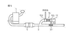
図5、図6は、図1のエネルギ回収装置により得られた低温源(冷熱)の利用例を説明する図である。
図5は、低温熱交換器(本実施形態では、図1の第2の熱交換器155が低温熱交換器になる場合を示す)をヒートパイプ53で排気管内に設けた熱交換器(排気冷却器)51に接続し、熱音響スタック15で発生した冷熱で排気を冷却する例を示している。
5 and 6 are diagrams illustrating an example of using the low temperature source (cold heat) obtained by the energy recovery apparatus of FIG.
FIG. 5 shows a heat exchanger (exhaust gas) in which a low-temperature heat exchanger (in this embodiment, the
このように排気冷却器51を用いて排気温度を低下させることにより、排気管を流れる排気の体積流量が低下するため、機関の排気背圧が低下して機関1の効率が改善される効果を得ることができる。
By reducing the exhaust temperature by using the
また、排気を冷却することにより同時に排気の圧力脈動も低下する。このため、排気騒音をも低減することができる。なお、この場合、排気冷却器51は排気管3の枝管接続部より上流側に設置すると排気脈動の低下のため熱音響スタックで回収可能なエネルギが低下してしまうため、排気冷却器51は枝管より下流側に設置することが好ましい。
Further, cooling the exhaust gas simultaneously reduces the pressure pulsation of the exhaust gas. For this reason, exhaust noise can also be reduced. In this case, if the
図6は、熱音響スタック15の低温熱交換器をペルチェ素子の積層体などからなる熱発電スタック61の低温源として使用し、排気管3内の排気を高温源として使用して発電を行う例を示す。図6の場合には、排気の脈動エネルギを最終的に電力の形で回収することが可能となる。
FIG. 6 shows an example in which power is generated by using the low-temperature heat exchanger of the
図7は、機関1の吸気マニホルド72に枝管11を設け、熱音響スタック15の低温熱交換器155をヒートパイプ73を介して吸気管2に設けた吸気冷却器75に接続した例を示す。
本実施形態では、吸気冷却器75により吸気を冷却することにより、機関1の吸気充填効率を増大させ、機関性能を向上させることが可能となる。
FIG. 7 shows an example in which the
In the present embodiment, the intake air is cooled by the
次に、本発明の別の実施形態について図8を参照して説明する。
図8は、枝管11内の共鳴圧力変化モードを示す図4と同様の図である。
前述したように、共鳴は脈動による定常波の波長λが枝管11の管長Lに対して、λ=4/(2n+1)となったとき(すなわち、管長Lがλ/4の奇数倍になったとき)に生じる。
Next, another embodiment of the present invention will be described with reference to FIG.
FIG. 8 is a view similar to FIG. 4 showing the resonance pressure change mode in the
As described above, resonance occurs when the wavelength λ of a standing wave due to pulsation is λ = 4 / (2n + 1) with respect to the tube length L of the branch tube 11 (that is, the tube length L is an odd multiple of λ / 4). When).
一方、λは脈動周波数に反比例し、脈動周波数は機関回転数に比例する。
このため、例えば、機関がある低回転領域(例えば1500rpm)で図8(A)に示す(1/4)λのモードの共鳴が発生した場合には、その3倍の回転数(4500rpm)では、図8(B)に示す(3/4)λモードの共鳴が発生する。
On the other hand, λ is inversely proportional to the pulsation frequency, and the pulsation frequency is proportional to the engine speed.
For this reason, for example, when resonance in the (1/4) λ mode shown in FIG. 8A occurs in a low rotation region (for example, 1500 rpm), the engine is three times as high (4500 rpm). Then, (3/4) λ mode resonance shown in FIG. 8B occurs.
前述したように、管内に定常波が発生すると熱音響スタックの圧力変化モードにおける腹側が高温になり、節側が低温になる。このため、例えば熱音響スタックを、図8においてIまたはIIIの領域に配置した場合は変化はないものの、IIの領域に配置した場合にはモードが異なると熱音響スタックの高温側と低温側とが逆転することになる。 As described above, when a standing wave is generated in the tube, the ventral side in the pressure change mode of the thermoacoustic stack becomes high temperature and the node side becomes low temperature. Therefore, for example, when the thermoacoustic stack is arranged in the region I or III in FIG. 8, there is no change, but when it is arranged in the region II, if the mode is different, the high temperature side and the low temperature side of the thermoacoustic stack Will be reversed.
この場合には、例えば排気管側の熱交換器(図1における第1熱交換器153)には冷却水を供給して、機関回転数にかかわらず第1熱交換器温度を一定に維持するようにすると、機関回転数(共鳴圧力変化モード)により、第2熱交換器155は高温熱交換器((1/4)λモード)と低温熱交換器((3/4)λモード)とに自動的に切替えられることになる。
このため、第2熱交換器からは低回転時には高温が、高回転時には低温が得られるようになる。
In this case, for example, cooling water is supplied to the heat exchanger on the exhaust pipe side (
For this reason, from the second heat exchanger, a high temperature can be obtained at a low rotation, and a low temperature can be obtained at a high rotation.
本実施形態では、この熱交換器温度の回転数による切替えを利用して、例えば機関の冷間始動後のアイドル運転では図7の吸気冷却器を吸気加熱器として利用し機関暖機を促進するとともに、暖機完了後の高回転運転では吸気を冷却して機関性能を向上させるようにしている。 In the present embodiment, using this switching of the heat exchanger temperature depending on the number of revolutions, for example, in idling operation after a cold start of the engine, the intake air cooler of FIG. 7 is used as an intake air heater to promote engine warm-up. At the same time, in high-speed operation after completion of warm-up, the intake air is cooled to improve engine performance.
なお、この場合、例えば機関の暖機完了後のアイドル運転などでは吸気の加熱は必要がなくなる。この場合には、例えば、図9に示すように枝管11の入口に遮断弁91を設け、低回転時に高温源が必要がない場合に(或は、高回転時に低温源が必要ない場合も)、遮断弁91を閉弁し枝管11内に共鳴が生じることを防止することも可能である。
In this case, for example, in idling after completion of warming up of the engine, heating of the intake air is not necessary. In this case, for example, as shown in FIG. 9, a shut-off
また、上記実施形態では熱交換器が低温源として機能する場合も高温源として機能する場合も同一の機器(吸気冷却/加熱器)に熱媒体を供給しているが、熱交換器が低温源として機能する場合と高温源として機能する場合とで、熱媒体を供給する機器を変更するようにすれば、排気圧力脈動エネルギを常に回収し有効に利用することができるようになる。 In the above embodiment, the heat exchanger is supplied to the same device (intake air cooling / heater) regardless of whether the heat exchanger functions as a low temperature source or a high temperature source. If the device that supplies the heat medium is changed between when it functions as a high-temperature source and when it functions as a high-temperature source, exhaust pressure pulsation energy can always be recovered and used effectively.
1 内燃機関
3 排気管
10 エネルギ回収装置
15 熱音響スタック
151 蓄熱器
153 第1熱交換器
155 第2熱交換器
DESCRIPTION OF
Claims (6)
一端が閉鎖端とされ、他端が内燃機関の吸気管もしくは排気管の所定位置に開口し前記吸気管もしくは排気管内の気体が流通する接続開口部とされた枝管と、
前記枝管内に配置された蓄熱器と、該蓄熱器の前記閉塞端側と前記接続開口部側とにそれぞれ設けられた熱交換器とからなるスタックとを備え、
前記スタックの一方の熱交換器は前記枝管内の気体と高温での熱交換を行う高温熱交換器として機能し、他方の熱交換器は前記枝管内の気体と低温での熱交換を行う低温熱交換器として機能し、前記高温熱交換器と低温熱交換器とから熱エネルギーの形で前記排気もしくは吸気の脈動エネルギを回収する内燃機関のエネルギ回収装置。 An energy recovery device that recovers pulsating energy of exhaust or intake air of an internal combustion engine,
One end is a closed end, the other end is opened to a predetermined position of an intake pipe or an exhaust pipe of an internal combustion engine, and a branch pipe that is a connection opening through which gas in the intake pipe or the exhaust pipe flows,
A heat accumulator disposed in the branch pipe, and a stack composed of heat exchangers respectively provided on the closed end side and the connection opening side of the heat accumulator,
One heat exchanger of the stack functions as a high temperature heat exchanger that exchanges heat with the gas in the branch pipe at a high temperature, and the other heat exchanger is a low temperature that exchanges heat with the gas in the branch pipe at a low temperature. An energy recovery device for an internal combustion engine that functions as a heat exchanger and recovers pulsation energy of the exhaust or intake air in the form of heat energy from the high temperature heat exchanger and the low temperature heat exchanger.
Priority Applications (1)
| Application Number | Priority Date | Filing Date | Title |
|---|---|---|---|
| JP2005352080A JP2007154792A (en) | 2005-12-06 | 2005-12-06 | Energy recovery device for internal combustion engine |
Applications Claiming Priority (1)
| Application Number | Priority Date | Filing Date | Title |
|---|---|---|---|
| JP2005352080A JP2007154792A (en) | 2005-12-06 | 2005-12-06 | Energy recovery device for internal combustion engine |
Publications (1)
| Publication Number | Publication Date |
|---|---|
| JP2007154792A true JP2007154792A (en) | 2007-06-21 |
Family
ID=38239480
Family Applications (1)
| Application Number | Title | Priority Date | Filing Date |
|---|---|---|---|
| JP2005352080A Pending JP2007154792A (en) | 2005-12-06 | 2005-12-06 | Energy recovery device for internal combustion engine |
Country Status (1)
| Country | Link |
|---|---|
| JP (1) | JP2007154792A (en) |
Cited By (6)
| Publication number | Priority date | Publication date | Assignee | Title |
|---|---|---|---|---|
| JPWO2009005086A1 (en) * | 2007-07-05 | 2010-08-26 | 日産自動車株式会社 | Temperature control device |
| JP2015183676A (en) * | 2014-03-26 | 2015-10-22 | 日野自動車株式会社 | internal combustion engine |
| US9291131B2 (en) | 2013-10-04 | 2016-03-22 | Denso Corporation | Vehicular air intake apparatus |
| CN107614868A (en) * | 2015-05-21 | 2018-01-19 | 中央精机株式会社 | Heat and acoustic power generating system |
| CN112145266A (en) * | 2019-06-26 | 2020-12-29 | 陕西汽车集团有限责任公司 | Device for recovering exhaust pulse energy of engine |
| JP2022072210A (en) * | 2020-10-29 | 2022-05-17 | 学校法人東海大学 | Thermoacoustic noise eliminator |
-
2005
- 2005-12-06 JP JP2005352080A patent/JP2007154792A/en active Pending
Cited By (9)
| Publication number | Priority date | Publication date | Assignee | Title |
|---|---|---|---|---|
| JPWO2009005086A1 (en) * | 2007-07-05 | 2010-08-26 | 日産自動車株式会社 | Temperature control device |
| JP5103474B2 (en) * | 2007-07-05 | 2012-12-19 | 日産自動車株式会社 | Temperature control device |
| US9291131B2 (en) | 2013-10-04 | 2016-03-22 | Denso Corporation | Vehicular air intake apparatus |
| JP2015183676A (en) * | 2014-03-26 | 2015-10-22 | 日野自動車株式会社 | internal combustion engine |
| CN107614868A (en) * | 2015-05-21 | 2018-01-19 | 中央精机株式会社 | Heat and acoustic power generating system |
| CN107614868B (en) * | 2015-05-21 | 2020-01-21 | 中央精机株式会社 | Thermoacoustic Power Generation System |
| CN112145266A (en) * | 2019-06-26 | 2020-12-29 | 陕西汽车集团有限责任公司 | Device for recovering exhaust pulse energy of engine |
| JP2022072210A (en) * | 2020-10-29 | 2022-05-17 | 学校法人東海大学 | Thermoacoustic noise eliminator |
| JP7422402B2 (en) | 2020-10-29 | 2024-01-26 | 学校法人東海大学 | thermoacoustic silencer |
Similar Documents
| Publication | Publication Date | Title |
|---|---|---|
| JP4441091B2 (en) | Exhaust heat energy recovery device for internal combustion engine | |
| EP3746724A1 (en) | A heat pump utilising the shape memory effect | |
| US6164073A (en) | Method and apparatus for adapting steady flow with cyclic thermodynamics | |
| WO2013084830A1 (en) | Thermoacoustic engine | |
| CN100371657C (en) | Pulse tube refrigerator | |
| JP2012112621A (en) | Thermoacoustic engine | |
| CN109312964B (en) | Thermoacoustic Engine and Design Method of Thermoacoustic Engine | |
| CN112303953B (en) | A waste heat driven refrigerator | |
| JP3857587B2 (en) | Refrigerator operating periodically | |
| JP2011208911A (en) | Thermoacoustic engine | |
| JP2006002738A (en) | Waste heat recovery device | |
| JP2007154792A (en) | Energy recovery device for internal combustion engine | |
| JP5453950B2 (en) | Thermoacoustic engine | |
| JP4737513B2 (en) | Cooling system | |
| JP5655313B2 (en) | Thermoacoustic engine | |
| CN100432572C (en) | Cryogenic chiller system with frequency modulating mechanical resonator and method of operating same | |
| JP5310287B2 (en) | Thermoacoustic engine | |
| JP5577984B2 (en) | EGR gas cooling device | |
| JP4580247B2 (en) | Engine system | |
| Mugisho et al. | Development of a thermoacoustically-driven thermoacoustic refrigerator powered by residual heat | |
| JP2005188846A (en) | Thermoacoustic heat pump water heater | |
| JP2002221089A (en) | Gas turbine cogeneration system | |
| JP5671907B2 (en) | EGR gas cooling device | |
| JP5446498B2 (en) | Thermoacoustic engine | |
| CN116398317B (en) | Free-piston Stirling power generation system based on a non-resonant self-circulating heat exchanger |